
JB74 Jimny LED headlight piggyback adapters
This is both a review and a how-to make your own. It goes into some details on the wiring harness, but I will do a more in depth writeup of this when I clean up my own
Sections
Headlight connector wiring for the JB74 LEDs
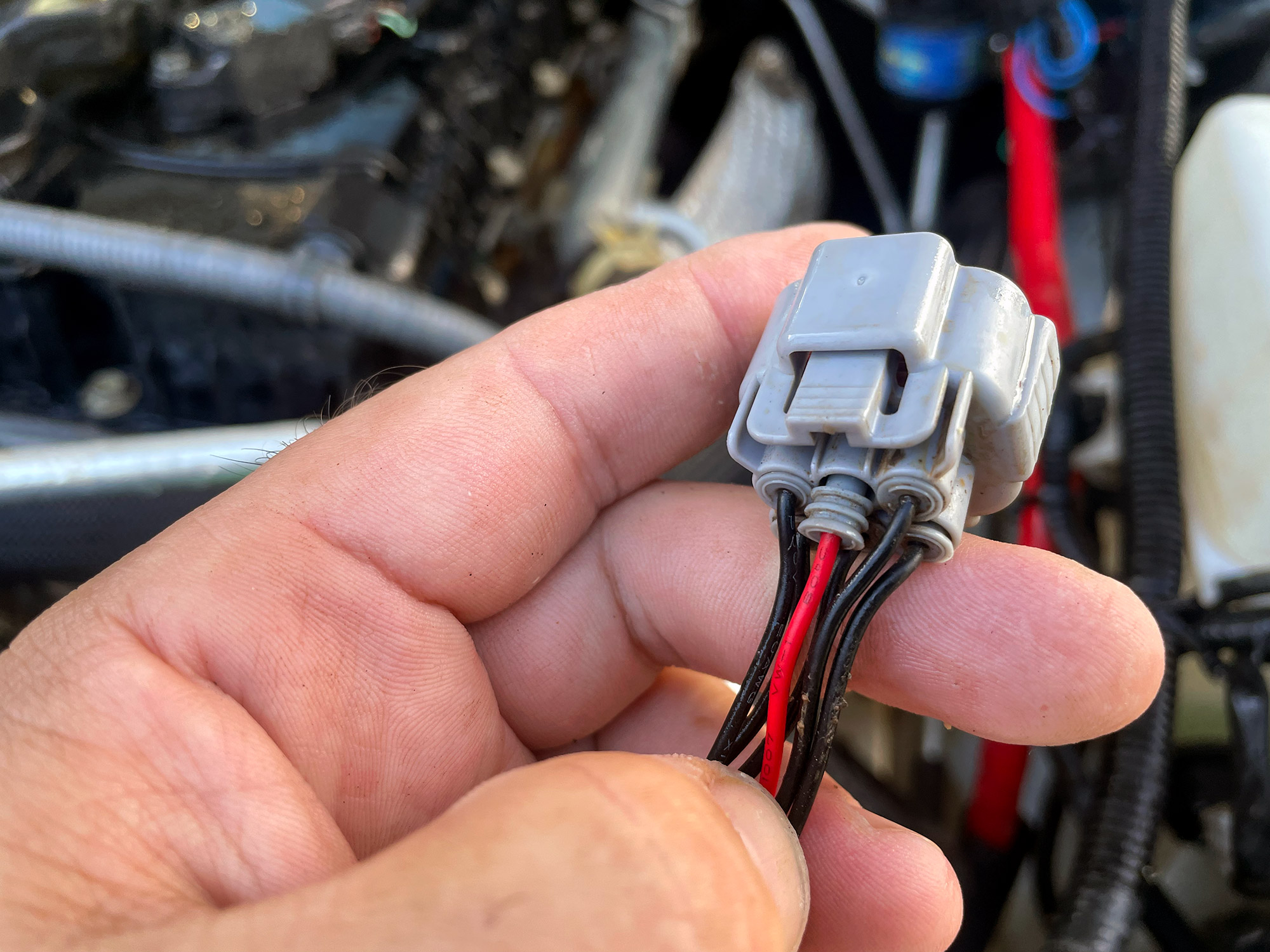
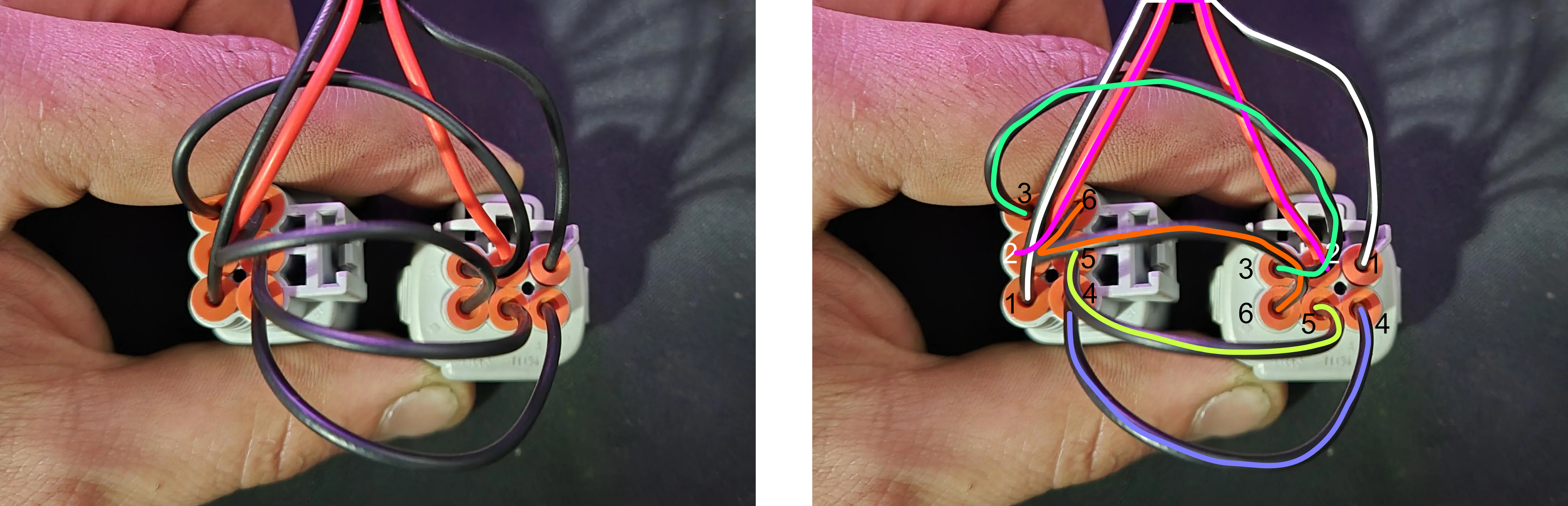
I’ll eventually draw up the full lighting circuit and host it over on my slowly growing collection of JB74 wiring diagrams but the key info you need is here:
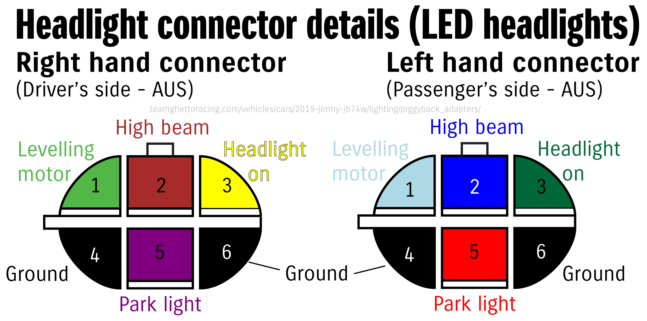
Just in case the picture doesn’t work for you, the wire colours and pinout using the standard Sumitomo pin numbering is as follows:
| Pin number | Wire colour | Item |
|---|---|---|
| 1 | Light blue (L); light green (R) | Headlight levelling motor |
| 2 | Blue (L); brown (R) | High beam |
| 3 | Green (L); yellow (R) | Headlight on signal |
| 4 | Black | Ground (headlight) |
| 5 | Red (L); purple (R) | Park light |
| 6 | Black | Ground (high beam) |
I’ve confirmed this against a few cars and also factory wiring looms. It might not be totally true for, say, a 5 door, but at least for 3 doors with LED headlights this is correct. Note that lites with halogen headlights use a standard H4 connector & are positively switched down at the headlight for auto-on headlight models.
Review of commercial adapters
A Jimny is often people’s first foray into modifying cars and lighting upgrades like lightbars or spot lights are very commonly one of those first modifications. People buy things that should be plug and play for the Jimny but often they are not. A huge amount of commercial adapters for the JB74 LED headlights do appear to be wired incorrectly. They work for some people, mostly depending on the wiring harness they are using it with, or if people are prepared to repin the connectors. I think it’s pretty disappointing that they aren’t wired correctly and I wanted to investigate further.
I don’t think it’s too much to ask for a relatively expensive item (almost as expensive as entire wiring looms with switches and relays and a lot more wires!) to work out of the box and be wired in a way that gives it its best chance at working straight away. While I do think it’s good to learn about how electric circuits work so you can diagnose and troubleshoot and fix things on the road, if you’re going down the path of buying plug and play things they should be exactly that and not require repinning or rewiring.
At the start of 2024 I ordered piggyback adapters from the following manufacturers
These cost me variable amounts but here’s a wrapup of both costs and postage timeframe from me in Perth. I didn’t include postage costs where applicable as likely you’ll be ordering other stuff from the same place at the same time and may get postage discounts I couldn’t. I ordered most of these via ebay as it was easier to quickly get them ordered. Store orders might be dispatched faster.
| Manufacturer | RRP (Jan 2024) | Days from order to dispatch | Freight service used | Transit time to Perth (business days) |
|---|---|---|---|---|
| STEDI | $34.99 | 0 (same day) | Auspost Parcel | 5 |
| Lightforce Australia | $28.00 | 0 (same day) | Auspost Parcel | 2 |
| Hardkorr | $25.00 | 1 (next day, accounting for holidays) | Auspost parcel | 6 |
| Air On Board | $28.00 | 1 (next day) | Auspost parcel | 4 |
Detailed view of adapters
As adapters arrive I’ll write up info on each of them plus picture how they are wired.
STEDI
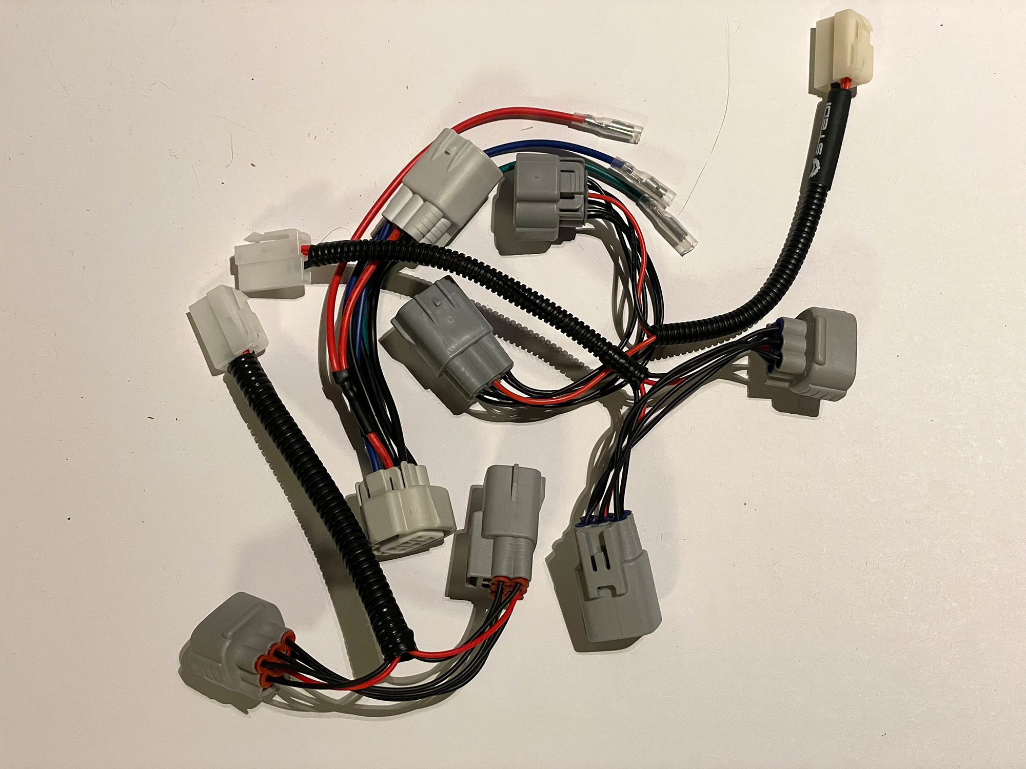
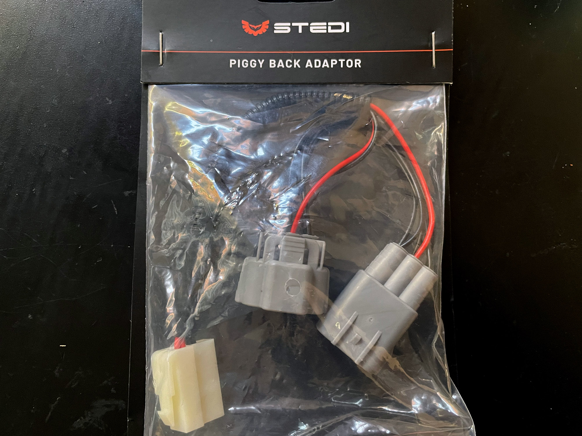
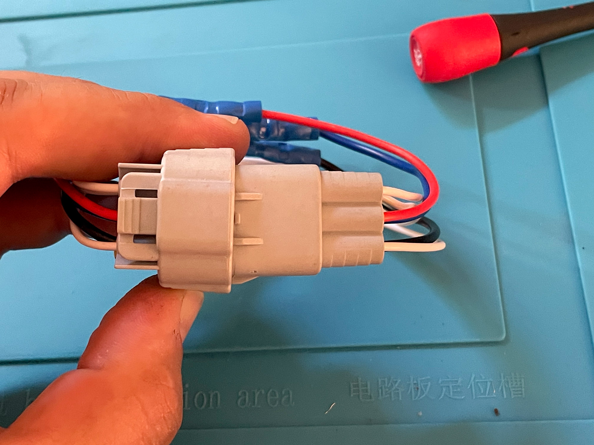
This is what I bought when I first got my car as it was the first available on the market. It’s the most commonly bought piggyback too, which also makes it the most commonly complained about piggyback adapter. They use a 90 degree T-fitting with spade terminals, which is unsealed, to connect to the rest of the wiring harness for the driving lights.
The version I bought in 2020 was fairly plain, the version now in late 2023/early 2024 comes with more Stedi branding on it along with the packaging. Note that it is also the most expensive piggyback adapter.
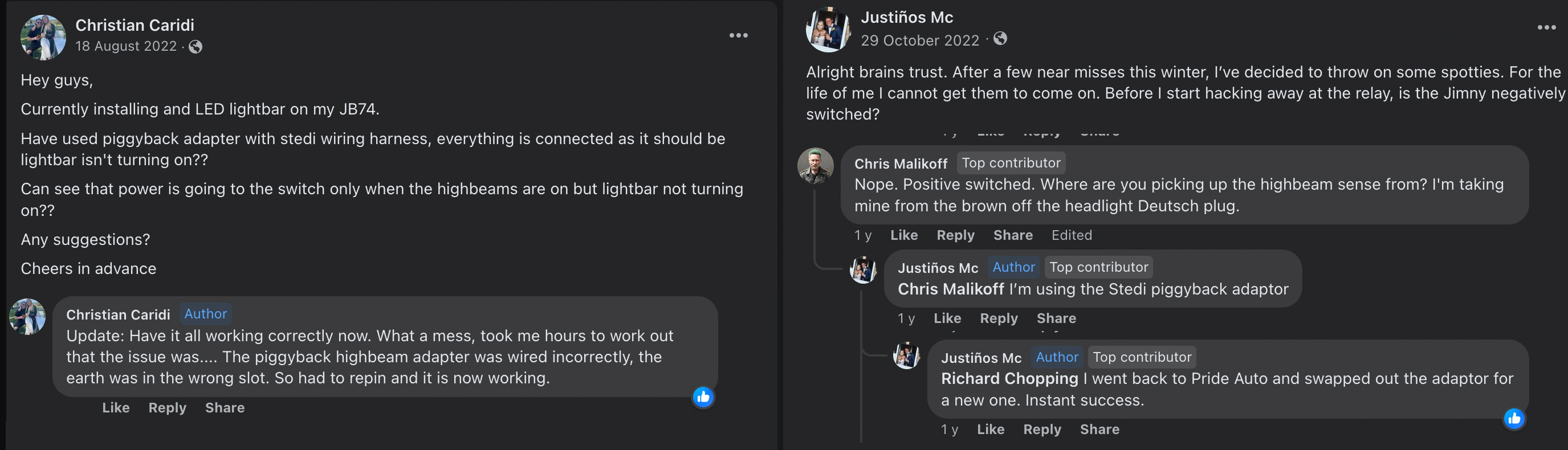
I have generally only cautiously suggest people buy this one due to the fact it seems to be most commonly sent wired incorrectly. A lot, going off various the Facebook group comments, do end up missing the ground pin or picking it up from the wrong spot, and so you might end up with one that doesn’t work. A couple of examples of this are below; not everyone says what adapter they’re using but a lot do buy the Stedi adapters.
I actually have two examples of this adapter, one of which I have used since early 2020. The one I bought in 2020 did work for me (and is wired up correctly), although the terminals are not well seated nor is are the sealing grommets for the connector seated well either.
You can actually see it back a fair way even in the photo I have prior to using it, after I’d adapted it to work with the Lightforce harness that came with my lights.
The other one, which I bought in early 2024 for this comparison, is made with more attention to detail. The wiring is similar to the thin factory wiring, probably 20 AWG. The adapters I have both correctly get the high beam signal off pin 2 and ground to pin 6.
As stated, this one has worked for plenty of people but others have had issues. If you can’t get your lights to work at first pass you should check the wiring of the piggyback adapter and if incorrect, raise a request to have it swapped.
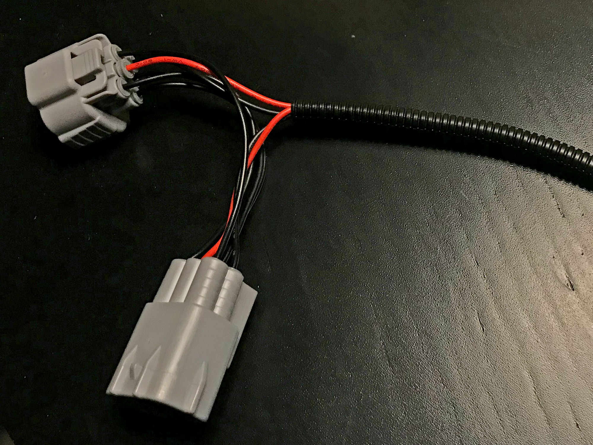
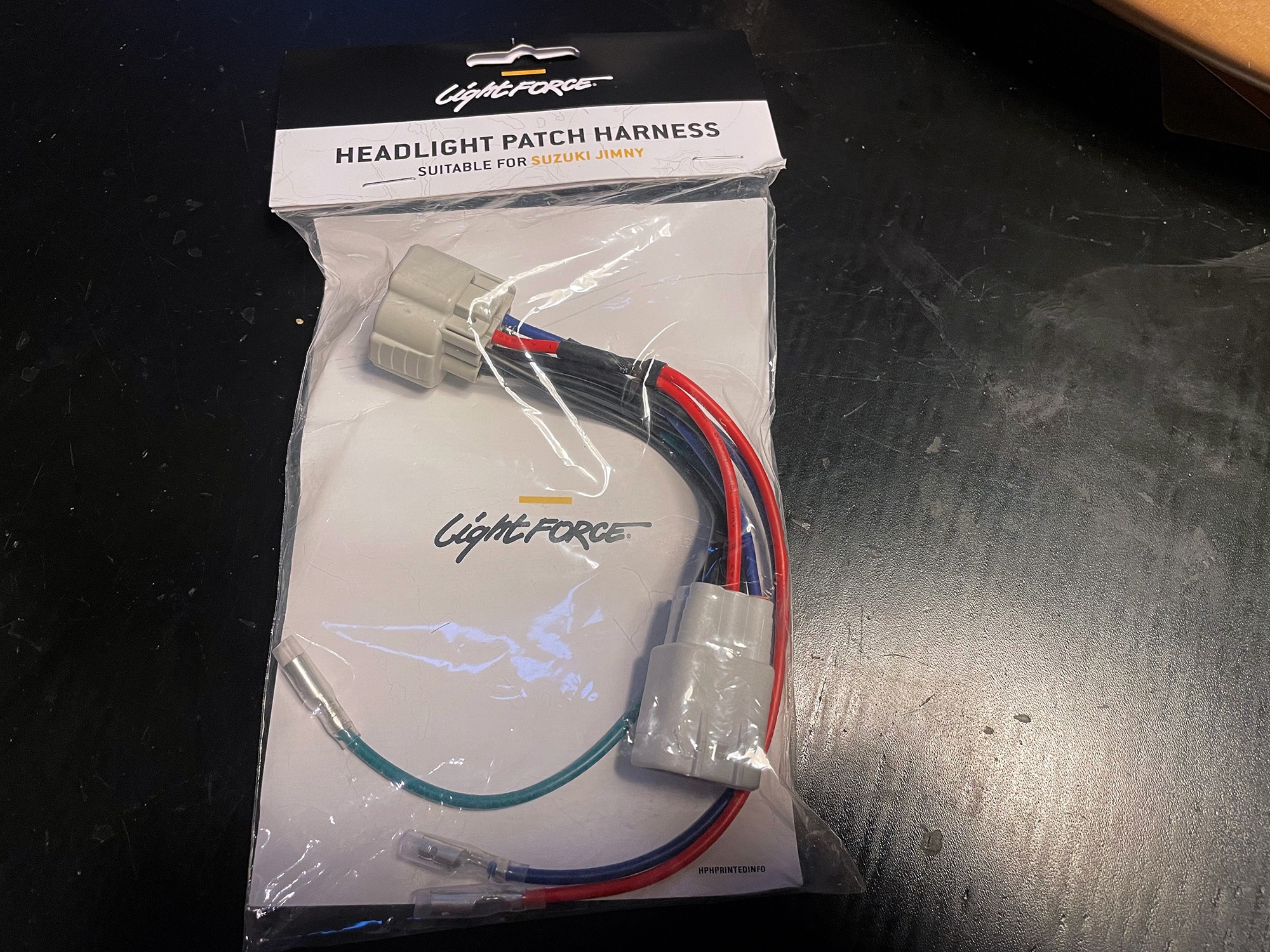
Lightforce Australia
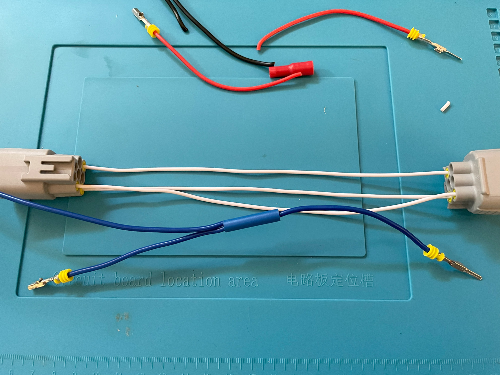
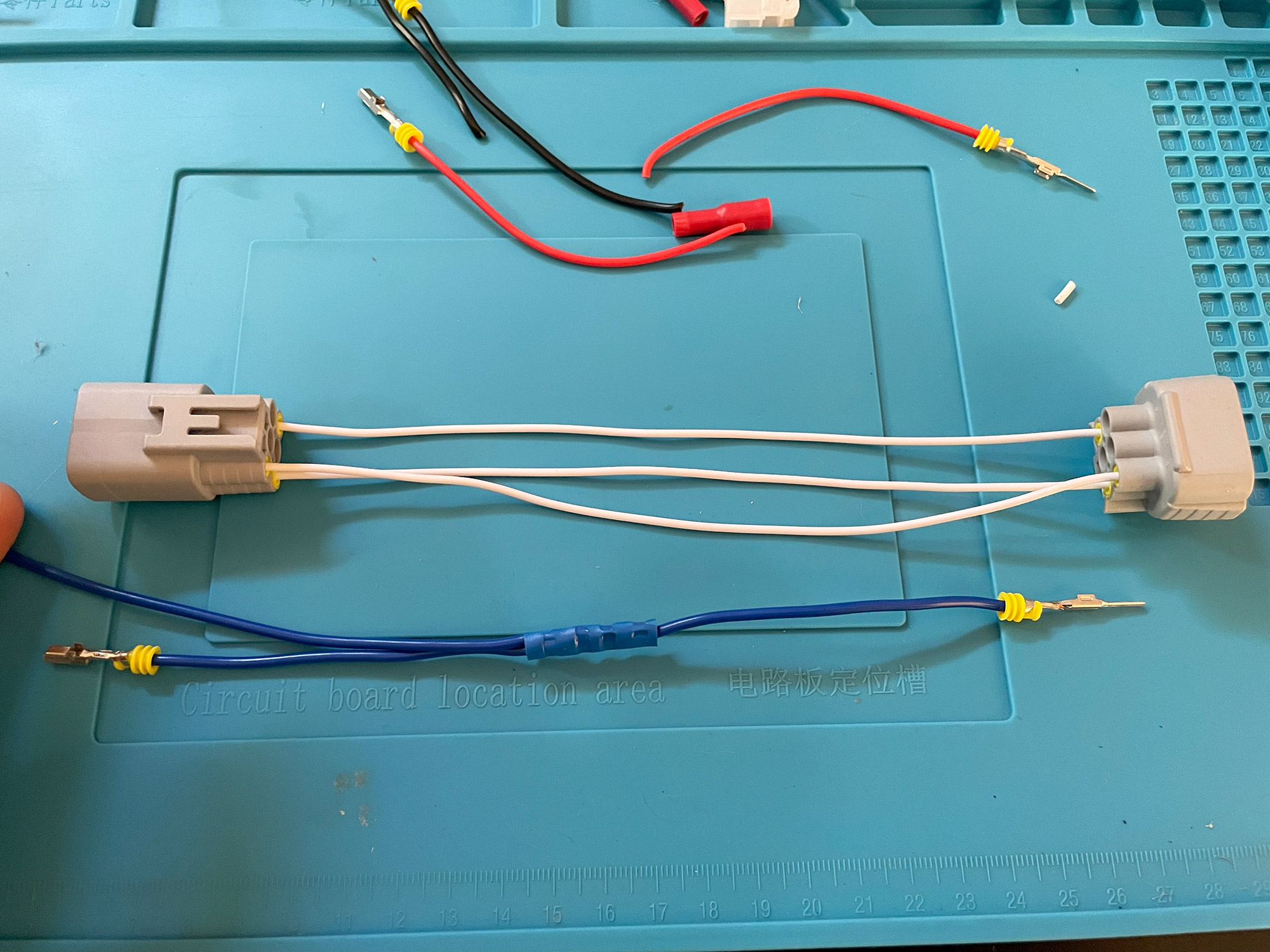
Surprisingly these were not the most expensive ones, and probably are the highest quality. The housings feel the nicest, they have used nicer cabling (and thicker wiring), and just higher quality joins.
These adapters give access to both the high beam (red wire) and low beam (blue wire) circuits, as well as the ground from the high beam circuit (green wire). The high beam line is what is useful for adding driving lights to a Jimny; if you want to use the low beam for something like additional lights in a bullbar (e.g. nighttime running lights) then it’s good to have that tap, along with the ground tap. You can also use it for switch illumination rather than tapping into dash switches. Note that the Lightforce harness does not require the ground tap to work correctly on the piggyback, but they do include it anyway.
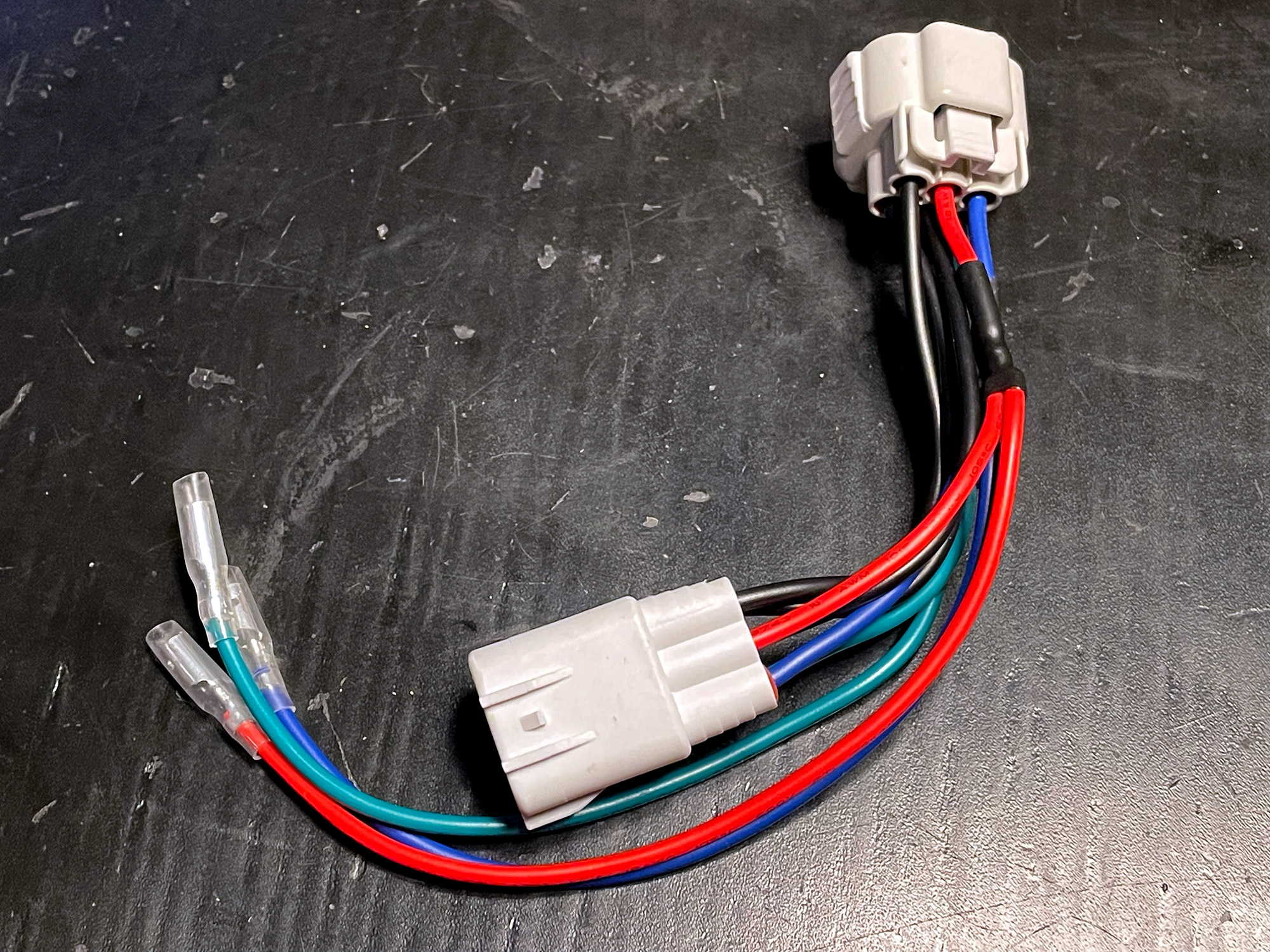
They use 4mm bullet terminals with sheaths to make them relatively sealed, basically motorcycle style wiring connectors. This makes them a bit more long term corrosion resistant than the other adapters.
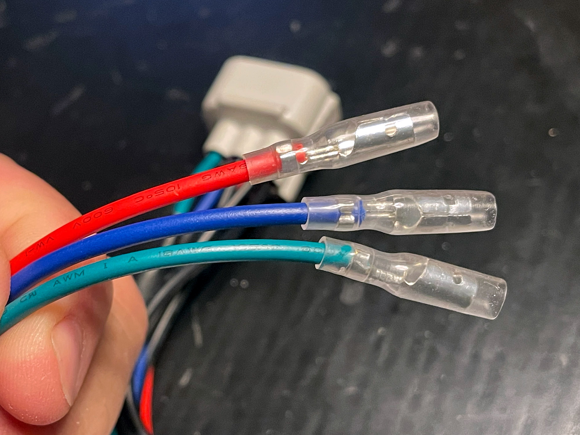
To ensure good waterproof connections, the junctions are solder joints with glue heatshrink covering them rather than into the crimp terminals in the fittings themselves. I much prefer this style of connection and it’s much more waterproof.
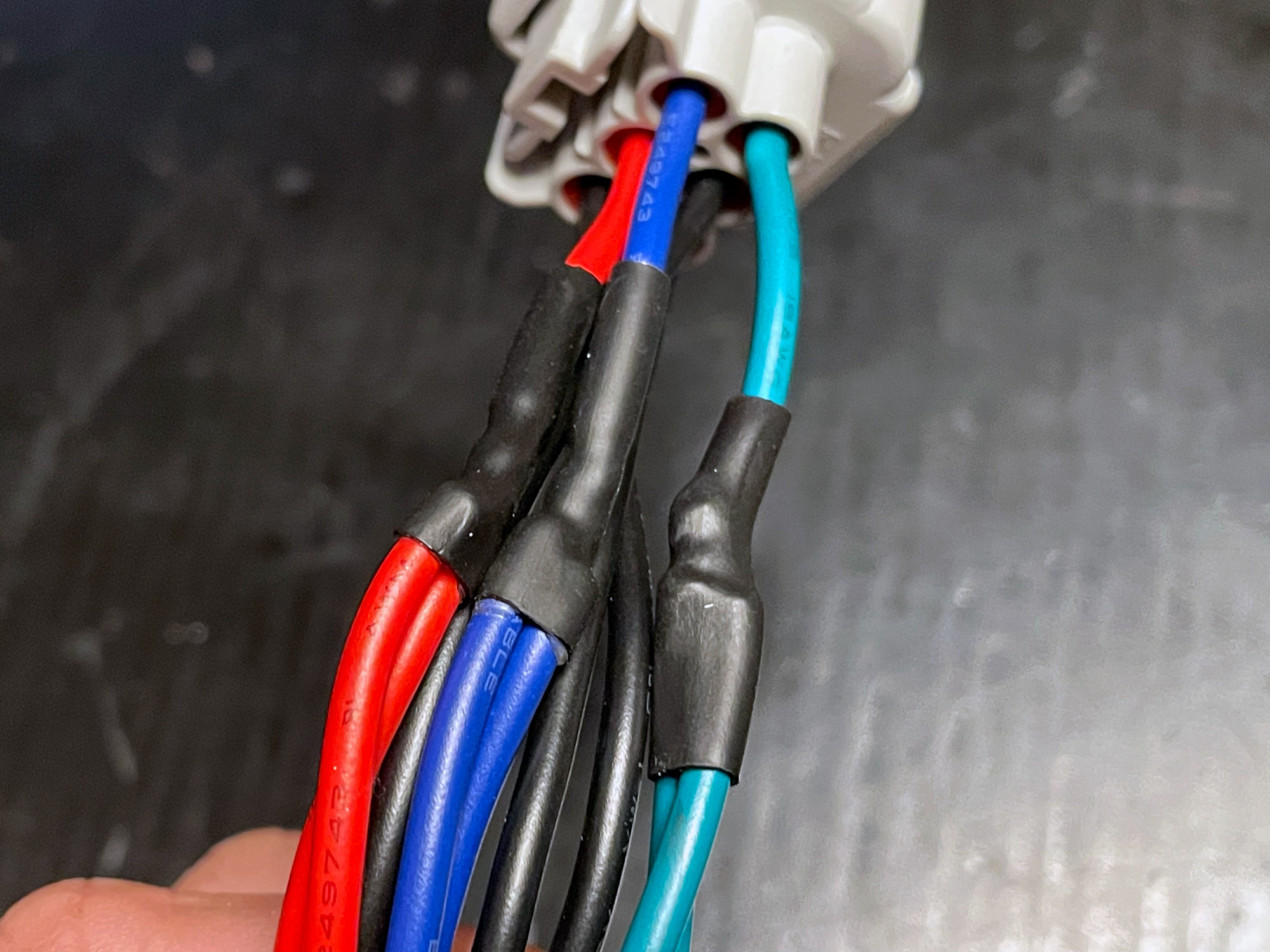
In addition, the insulators are all deeply seated into the connector housing and the best waterproofed of any of the adapters I received.
One slight twist to this tale, though: the first connector Lightforce sent me was wired incorrectly. As I stated it would have worked with their harness and its independent ground but didn’t correctly provide a ground wire that some harnesses for lightbars/driving lights might need.
I emailed them and provide a picture and they were very quick to do both of the following actions:
a) Send me out a new connector – dispatched immediately
b) Provide me return paid to ship back the old adapter.
This is among some of the best service around a defective part I’ve received in general, especially considering there would be limited margin in the piggyback adapters (even just the post to me is 1/3rd of the adapter!). I would absolutely not hesitate to recommend Lightforce based on this experience.
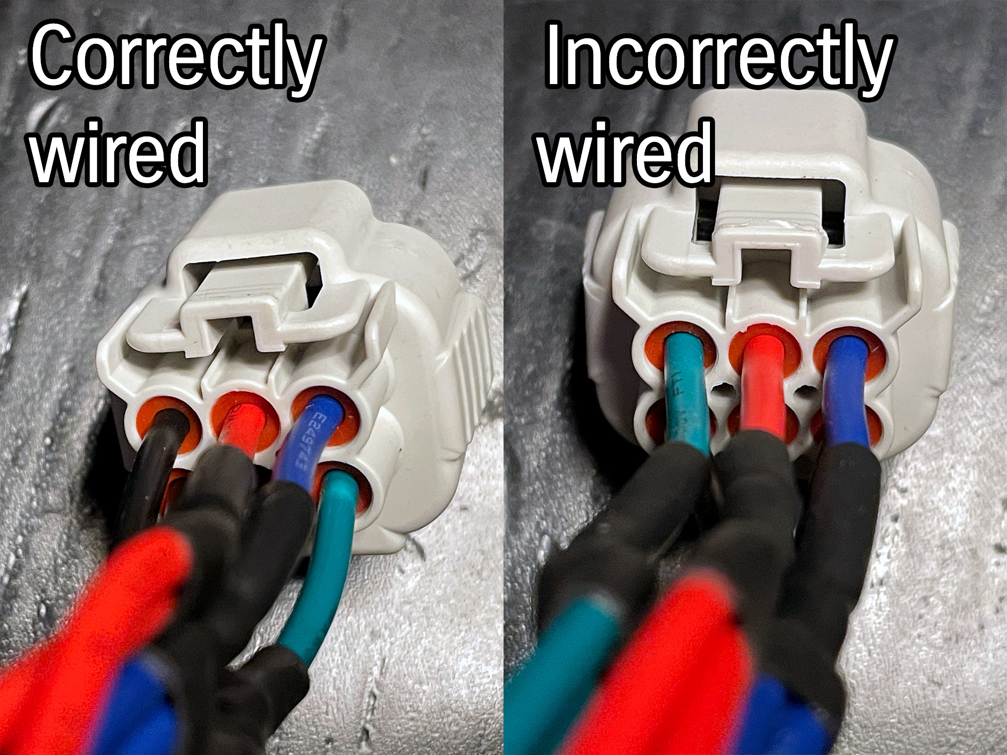
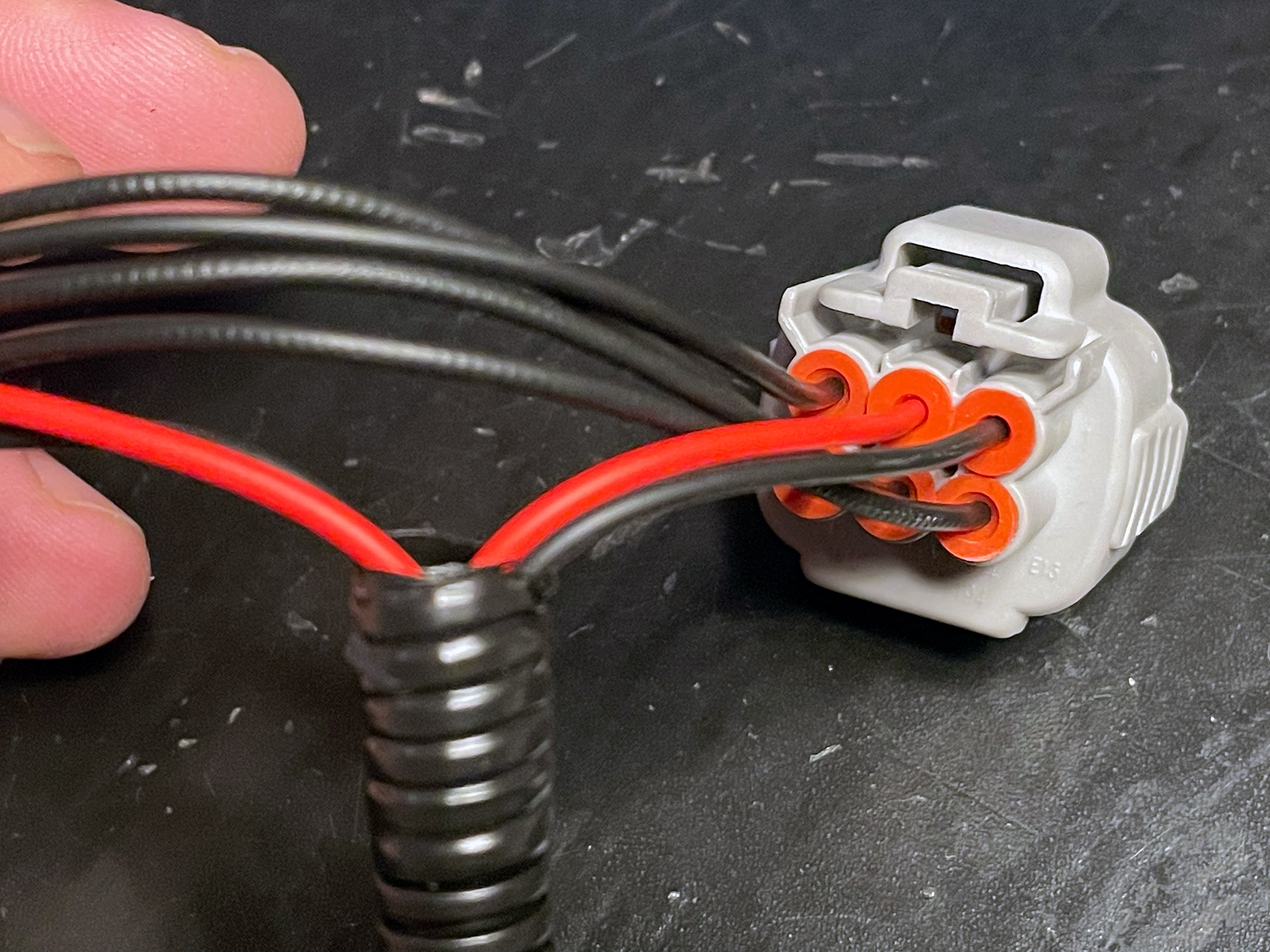
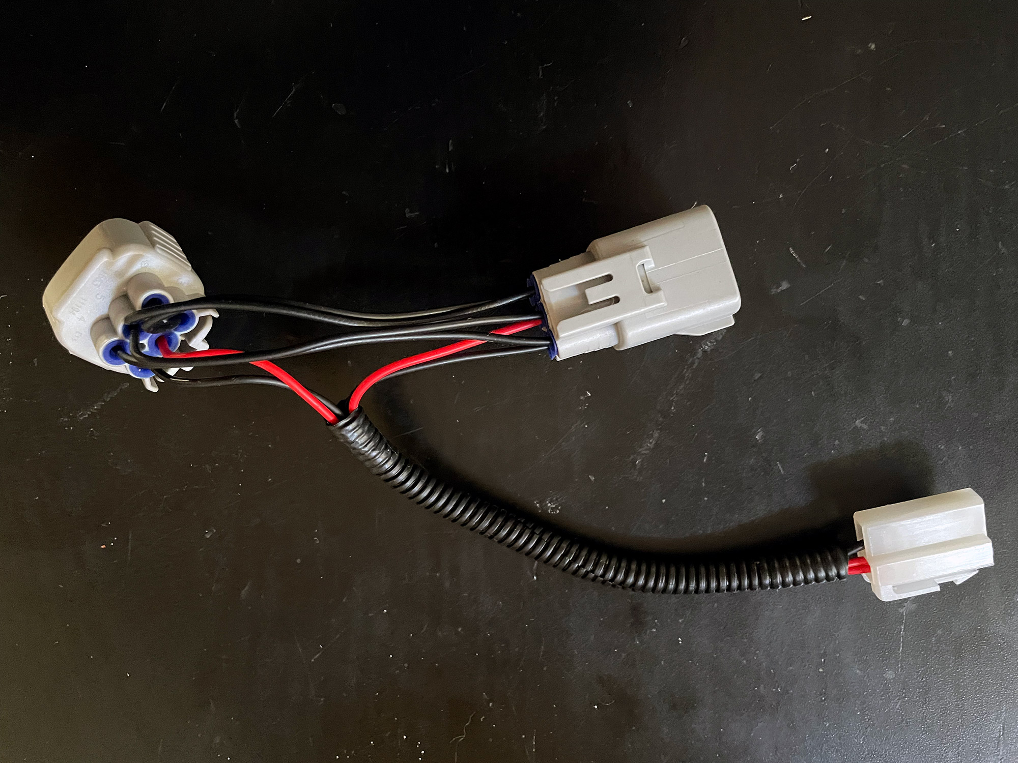
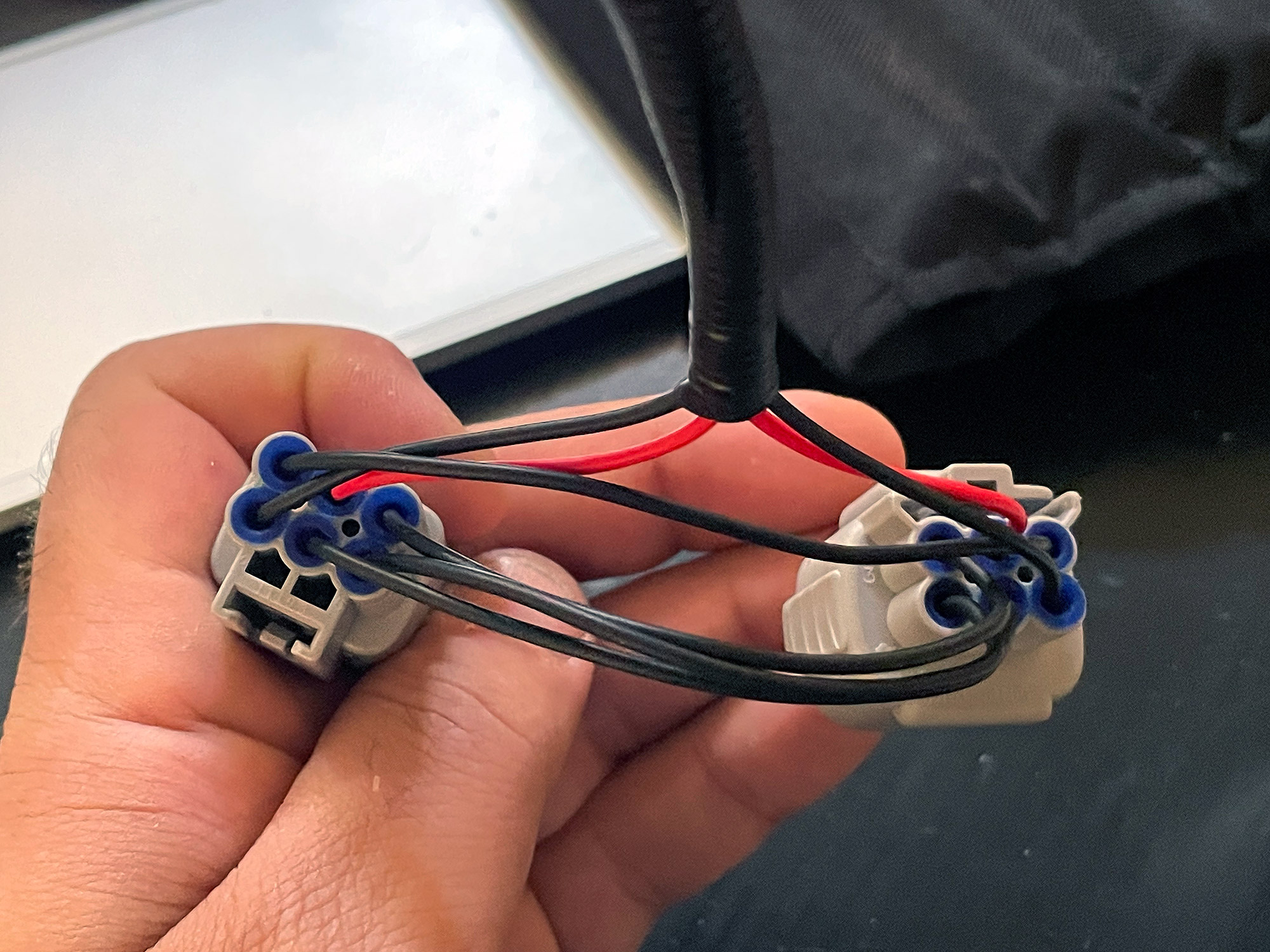
Just so you know what to look for, here’s the difference between correctly wired (left) and incorrectly wired (right):
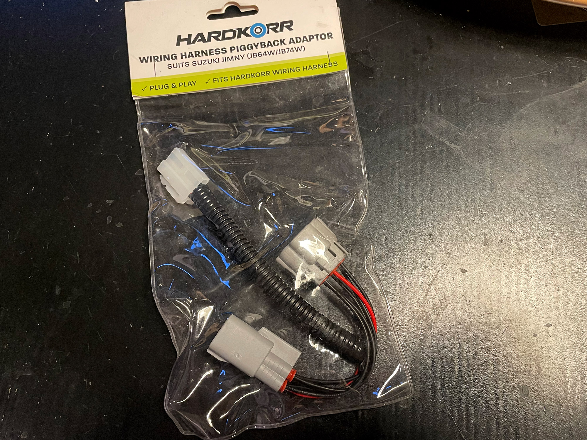
Hardkorr
Much like the STEDI adapter, these use the 90 degree T spade connector for the rest of the wiring harness connection. The wiring is ~20 gauge and surprisingly quite stiff, which might make it prone to fatigue over time which might make some of the wires break and parts of your headlight not work on the side that it is connected to.
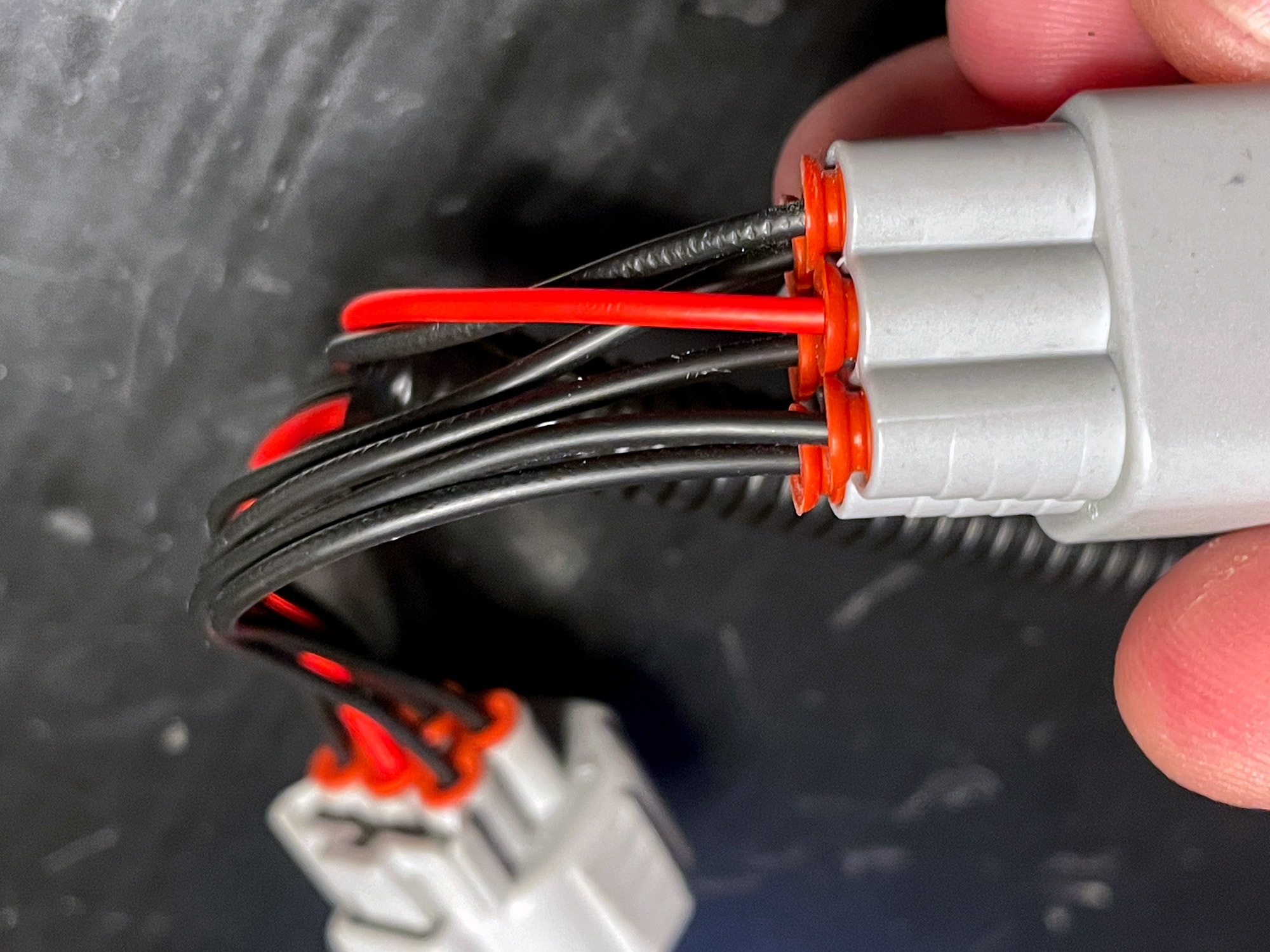
There are only two wires pulled out: high beam (as a red wire) and (presumably) a ground (as a black wire to the T connector for the rest of the auxiliary light wiring).
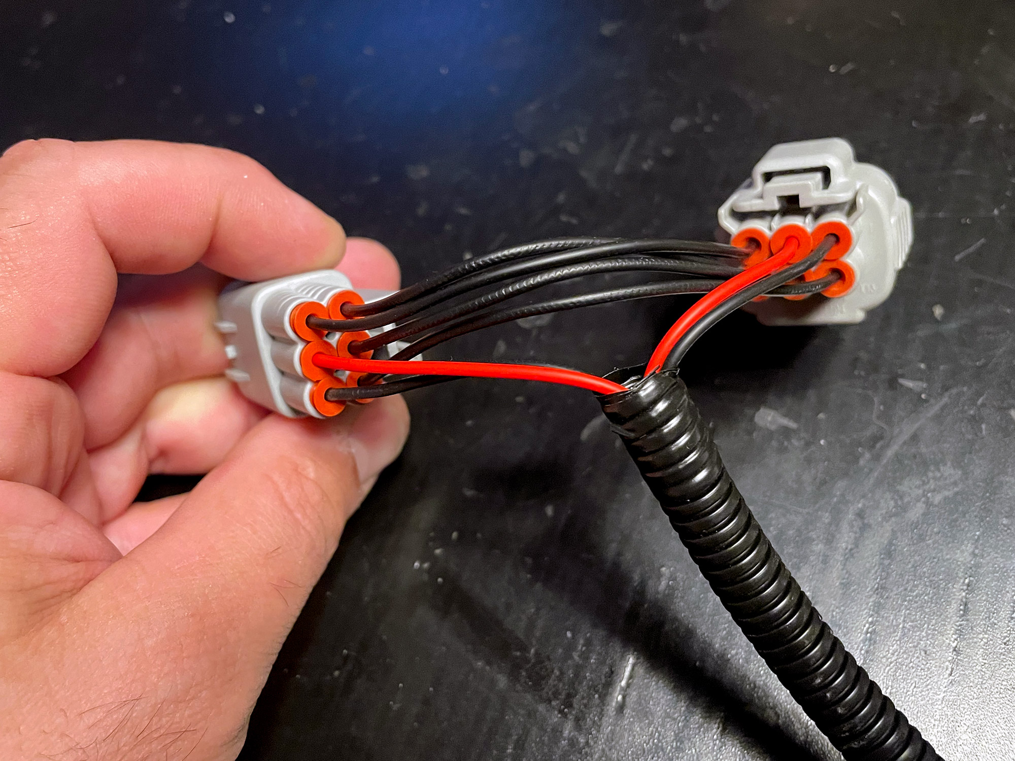
That picture actually highlights something that I don’t like about these: they have used a couple of different sized wire insulators and so some of the wires are not even properly waterproofed. In addition, a number of the insulators were not correctly seated, again potentially causing you issues down the road.
I say nominally, as the wiring actually is grabbing low beam as the black wire out to the harness, rather than a ground.
I will attempt to get a resolution to this but I did buy it through a reseller and it seems returns are potentially at my expense. You’ll see this is a theme for some of these adapters.
Air On Board
Another one using the same 90 degree T spade connector. Same sized wiring as all but the Lightforce one, and this one did turn up incorrectly wired. The pin that should be connected to the ground pin instead is connected to pin 3, the low beam headlight pin. This could be useful if you want a low beam headlight function on your lights e.g. a low power DRL setting that some offer but it will not correctly trigger the relays in most wiring harnesses.
I didn’t contact AOB to exchange this, the ebay listing states:
One year warranty is offered by Air On Board and will be honored by us. The buyer is responsible for return shipping costs and insurance. All shipping and handling fee will not be returned in any case.
Instead I’ve used this adapter to illustrate how to fix up an incorrectly wired adapter. Given it costs the same as the Lightforce adapter which is made considerably better I certainly can’t recommend it on this basis.
Wrapup
Although all of the adapters are nominally only intended to be used with individual wiring harnesses, most harnesses are universal enough that they can be made to work with others. However, the vast majority of harnesses out there require the earth side of the headlight piggyback to be connected up.
| Adapter | Connectors/insulators seated? | High beam trigger correct? | Ground correct? | Low beam (optional)? | Recommended? |
|---|---|---|---|---|---|
| STEDI | Yes, though a couple pushed back on one I bought in 2020 | Yes | Yes and passed through | No | Yes, but check it when it arrives |
| Lightforce | Yes, all perfectly | Yes | Yes(*) | Yes, pin 3 correct | Yes, but check it when it arrives |
| Hardkorr | Many inadequately seated | Yes | No (hooked into low beam) | Yes (though presumably not deliberately) | No |
| Air On Board | Reasonably well | Yes and passed through | No (hooked into pin 3 low beam instead) | Yes (though presumably not deliberately) | No, and their T&Cs have you on the hook for postage to return an incorrectly wired adapter |
Technical details on why yours might not be working
To make installation easier, most of the commercial patch harnesses use both the high beam ground and high beam positive circuit for the switching side of the relay to make the driving lights work. This saves on a bit of wiring and also one fewer thing to connect.
Many are also wired this way as it’s the simplest way to potentially make them compatible with both positively switched (most cars) and negatively switched (some Toyotas and a few other random things) headlights. Positively switched means the ground is always there, but the positive feed to the high beam only happens for high beam. In negatively switched circuits the power is there all the time but the ground for the high beam is only activated when they are on.
You can switch circuits both ways relatively easily, though on some harnesses (e.g. the Kings harnesses from 4wd supacentre) you have to repin one side of the adapter to make it work. Others (e.g. the STEDI smart harness) nominally detect negatively or positively switched wires with microprocessors or it’s done just through good electronics (e.g. Lightforce).
If the harness uses the ground wire on the piggyback adapter to ground the relay for switching on the relay then it will probably work with any piggyback so long as the high beam wire is correctly connected. If the harness uses the negative wire to ground the driving light relay OR to ground the driving lights themselves then if they are wired incorrectly they won’t work. Potentially you may also end up shorting it to ground and blowing a fuse in the high or low beam circuit especially in the case of smart harnesses that can get confused as to what voltage is meant to be where.
If you want to diagnose what’s going on with your adapter if it doesn’t work, get any multimeter (yep, down to a $10 cheapy) and set it to DC voltage up to 20V. Check the voltage between the red and the black pins out from the piggyback adapter to the wiring harness. You should get battery level voltage with the car running and high beam on. If you don’t see this, put the negative lead of the multimeter directly to battery negative and check the voltage again. If this works then it means the piggyback adapter is not earthing correctly and you should check the pinout they have used based on the figure at the top of this page.
If the harness you are using requires the earth to come back to the headlight then you can either repin the adapter or just separately ground the returning black wire from the relay and it should be ok.
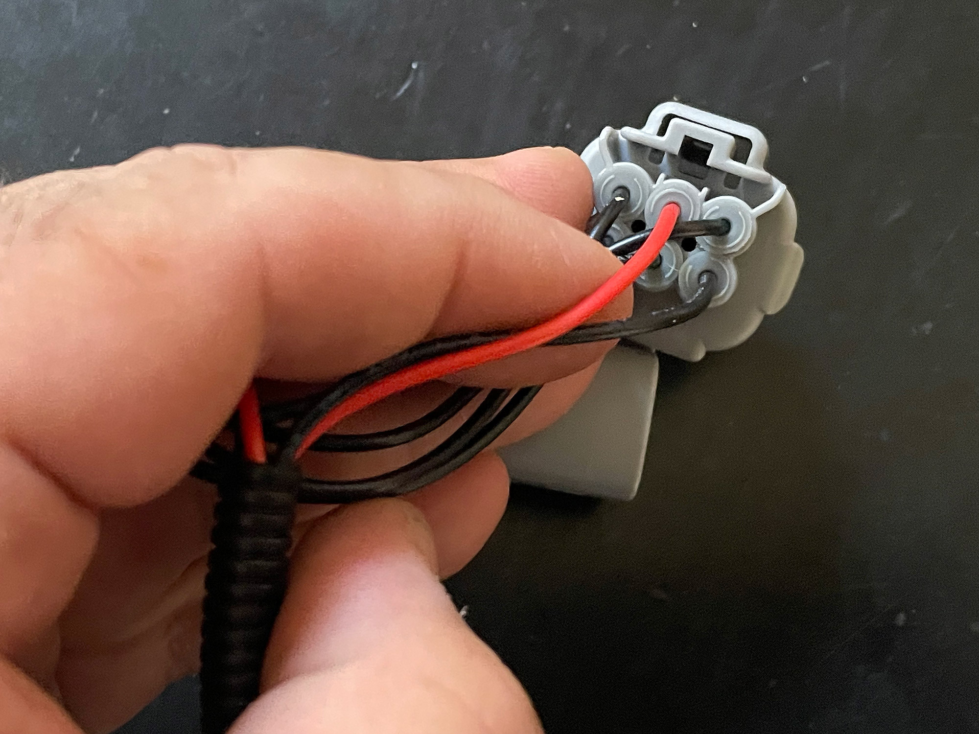
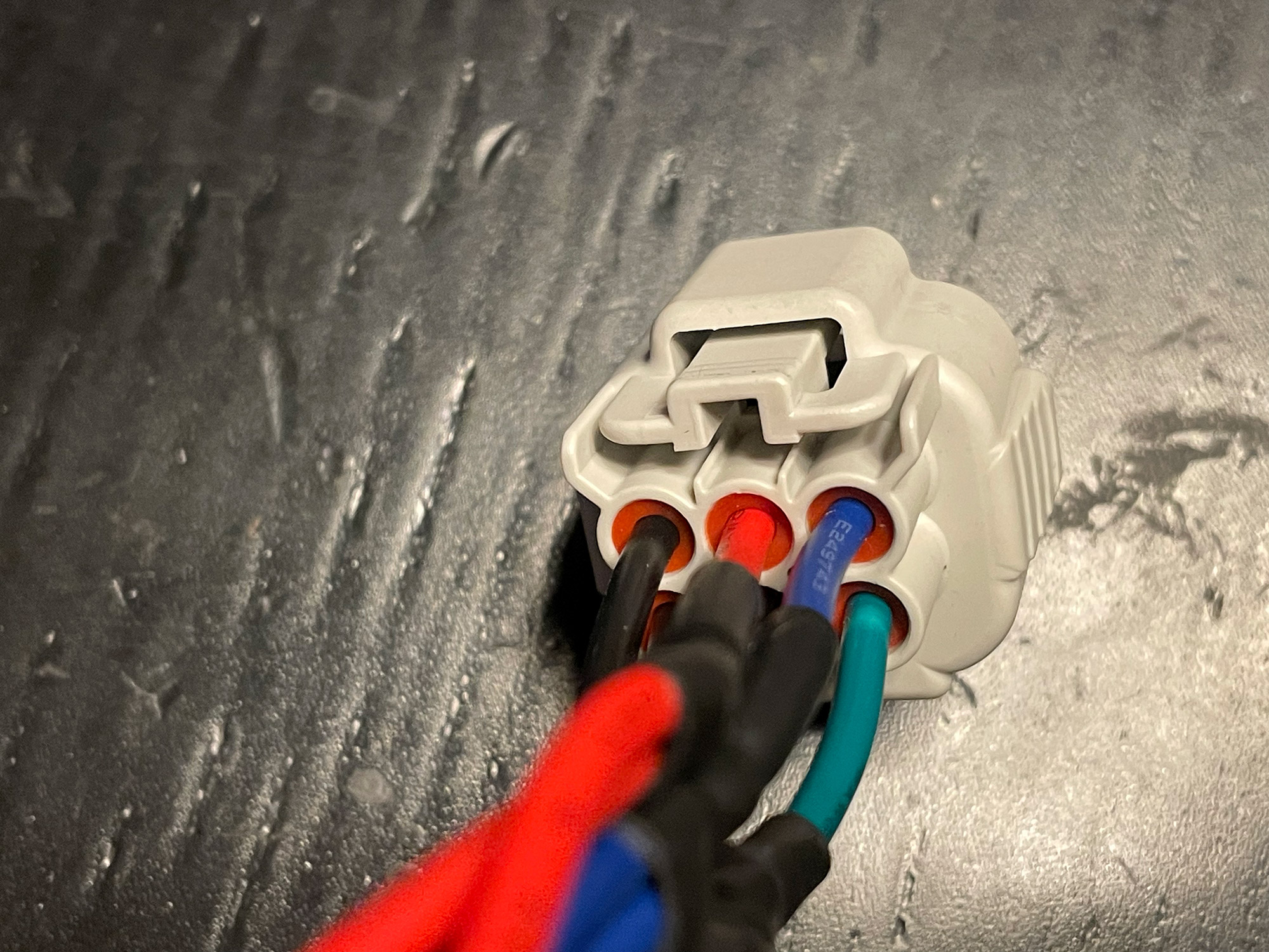
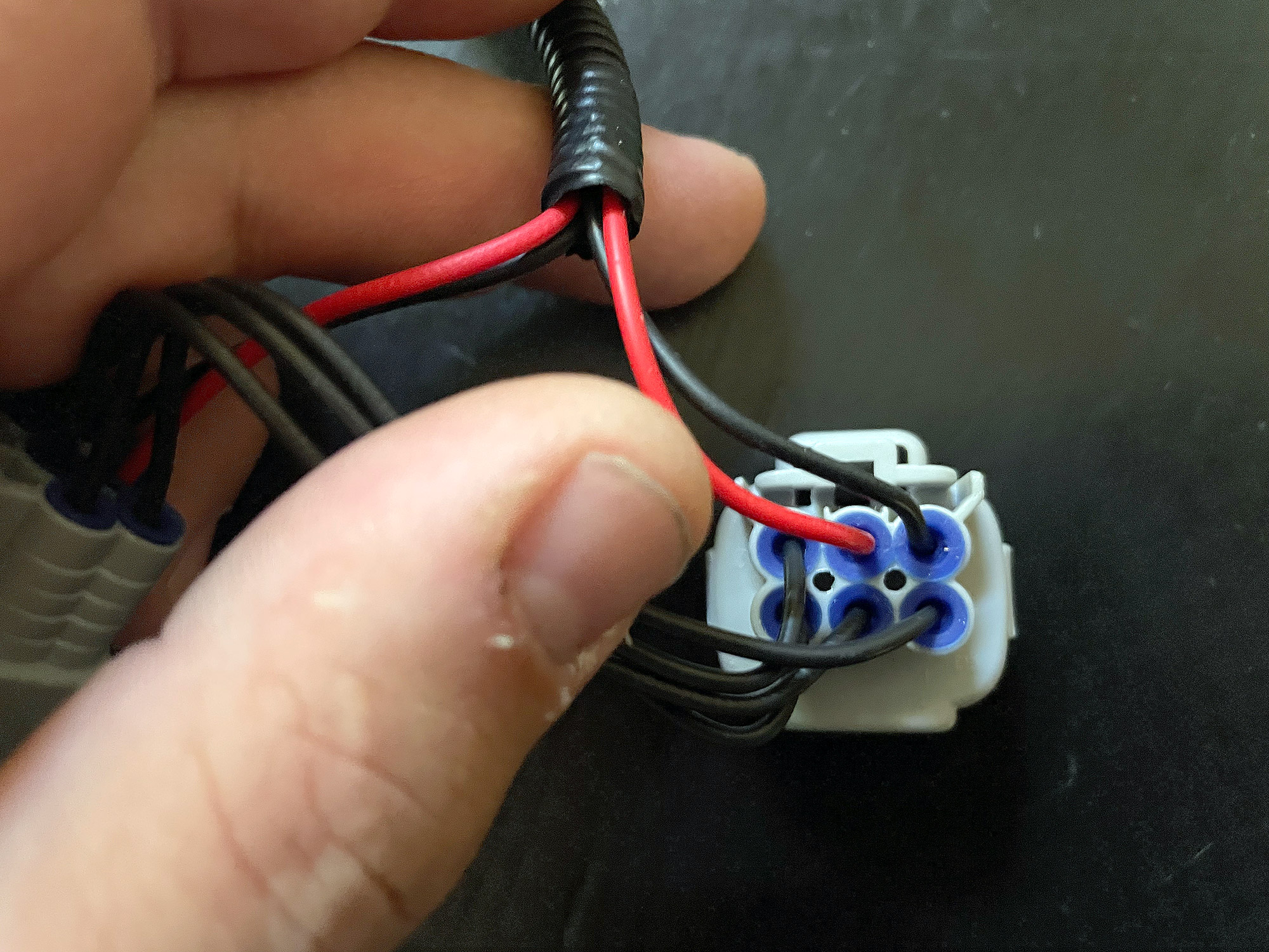
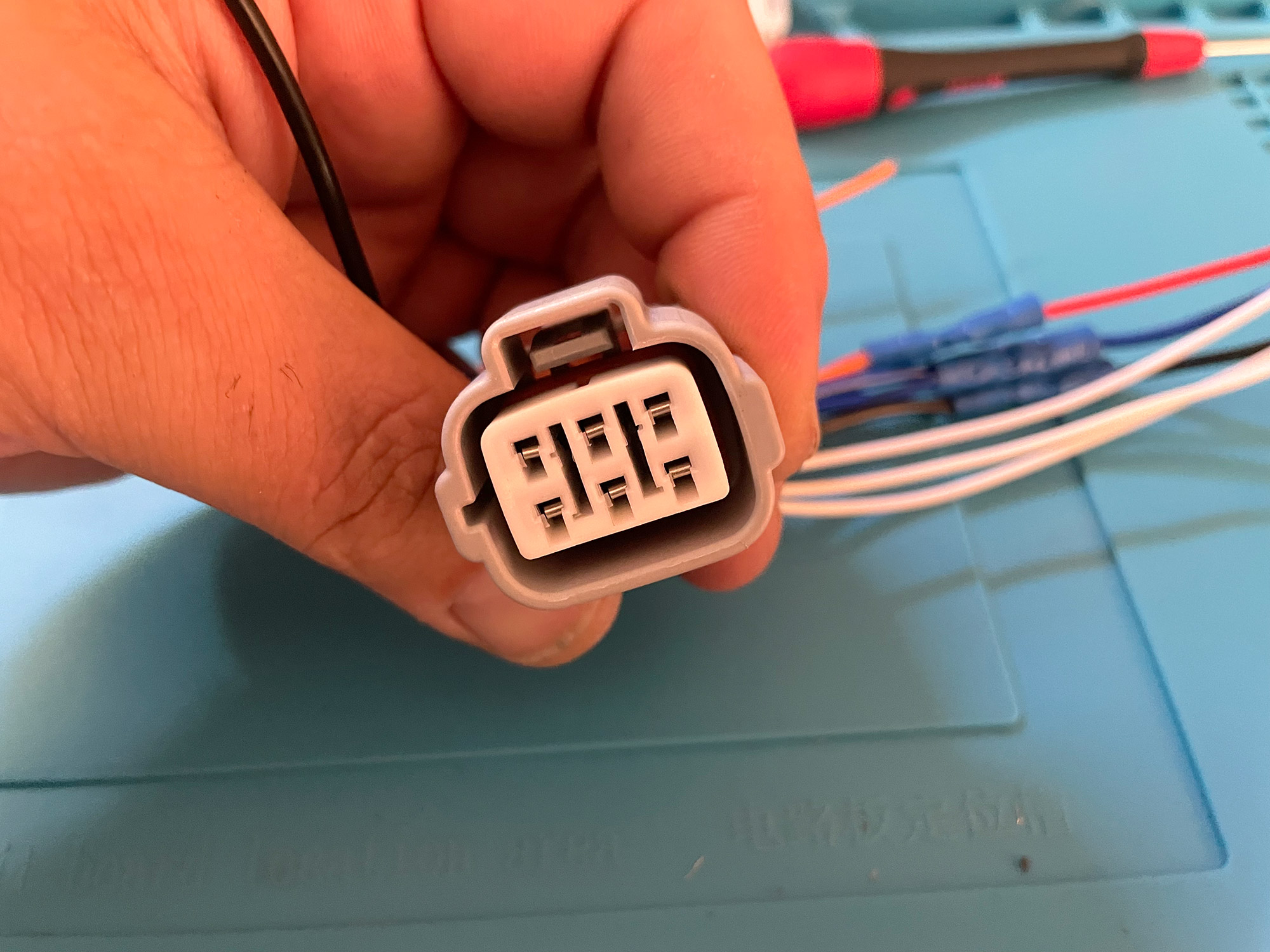
Identifying what’s wrong
This can be a little tricky if you’re not familiar with the Jimny’s headlight connectors, but in essence think of the connector as two rows of 3 pins. With the red wire (or whatever colour they’ve used for the high beam +ve signal) out to the driving light relay harness at the top of the two rows, the black wire should be coming from one of the two outer bottom row pins to get an earth signal. If it isn’t but instead is coming from one of the upper pins then it’s wrong. If you swap this pin with the one that’s beneath it then you should be right, assuming it’s to the side of the red wire.
Here’s an example from Facebook of me showing what needed to be done:
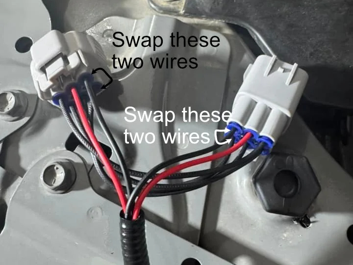
and another example from Reddit where I traced through the wiring in the picture to verify what pin was connected to what:
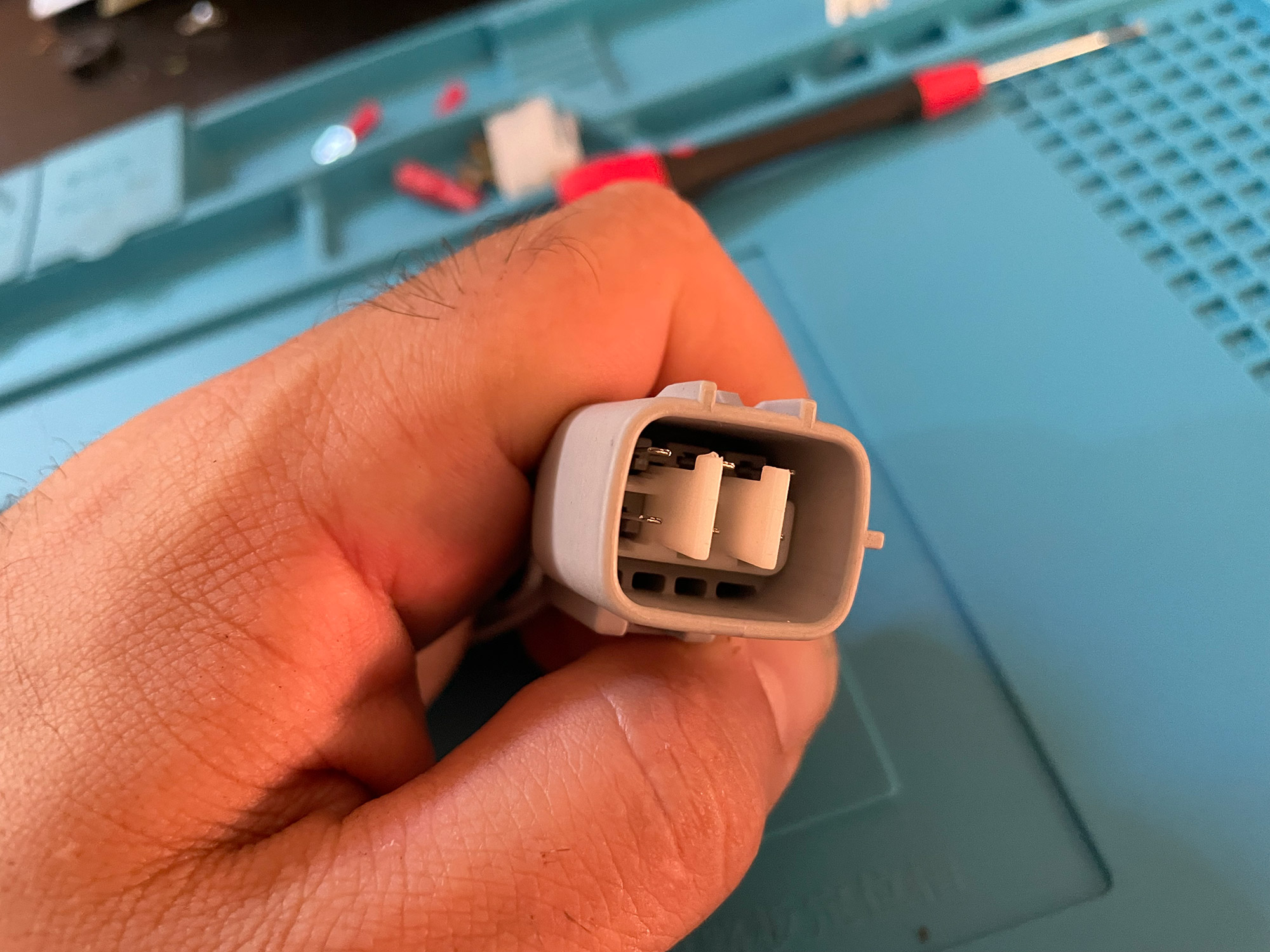
Note that pin number is mirrored between the male and female connectors: think about what happens when the male is plugged into the female connector & what pins connect with what. Once you get your head around what needs to be done then it’s a simple case of repinning the connector.
Fixing an incorrectly wired adapter
Assuming you have access to some very small screwdrivers/picks or similar, it’s not hugely difficult to repin the connector to make it work correctly. Just remember to mirror the pins into the back between the female and male connectors as they have to match when passing wires through etc. If you don’t potentially you could directly short low or high beam to ground and blow fuses etc.
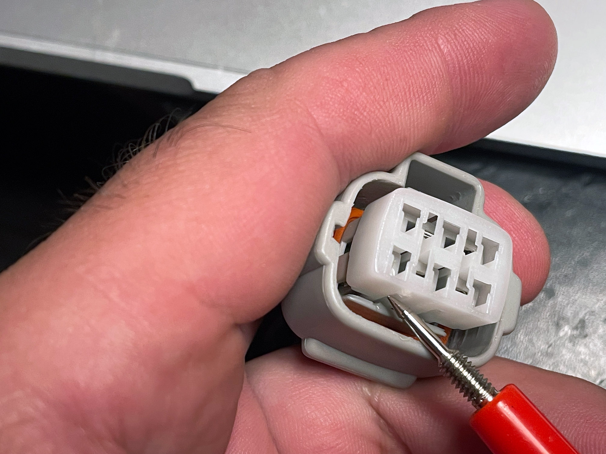
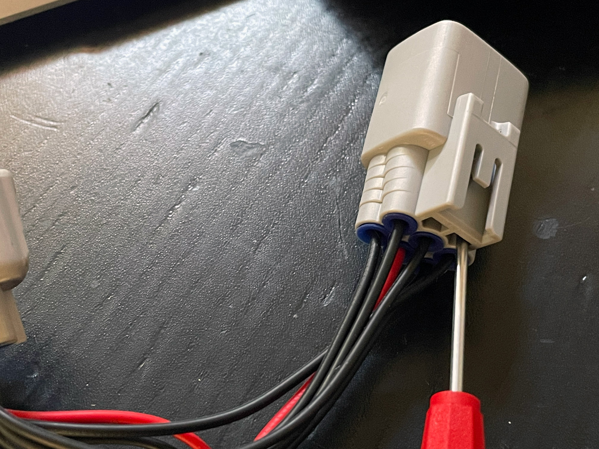
The female connector is the easier one to repin as it is quite obvious how to remove the central white pin retention clip. In this follow pic I use a multimeter probe to push in one of the two clips that hold it in. You can kinda lift one side up a little and then access the other side’s clip and lift it totally out as shown here.
With that done, you have access to the clips that actually hold the pins in fully. These pull away from the metal terminal and let you get the terminal back out of the housing. In this picture I’ve removed both one of the ‘lower’ set of terminals, currently just passed through from one connector to the other, and the upper one which is going out to the wiring harness connector.
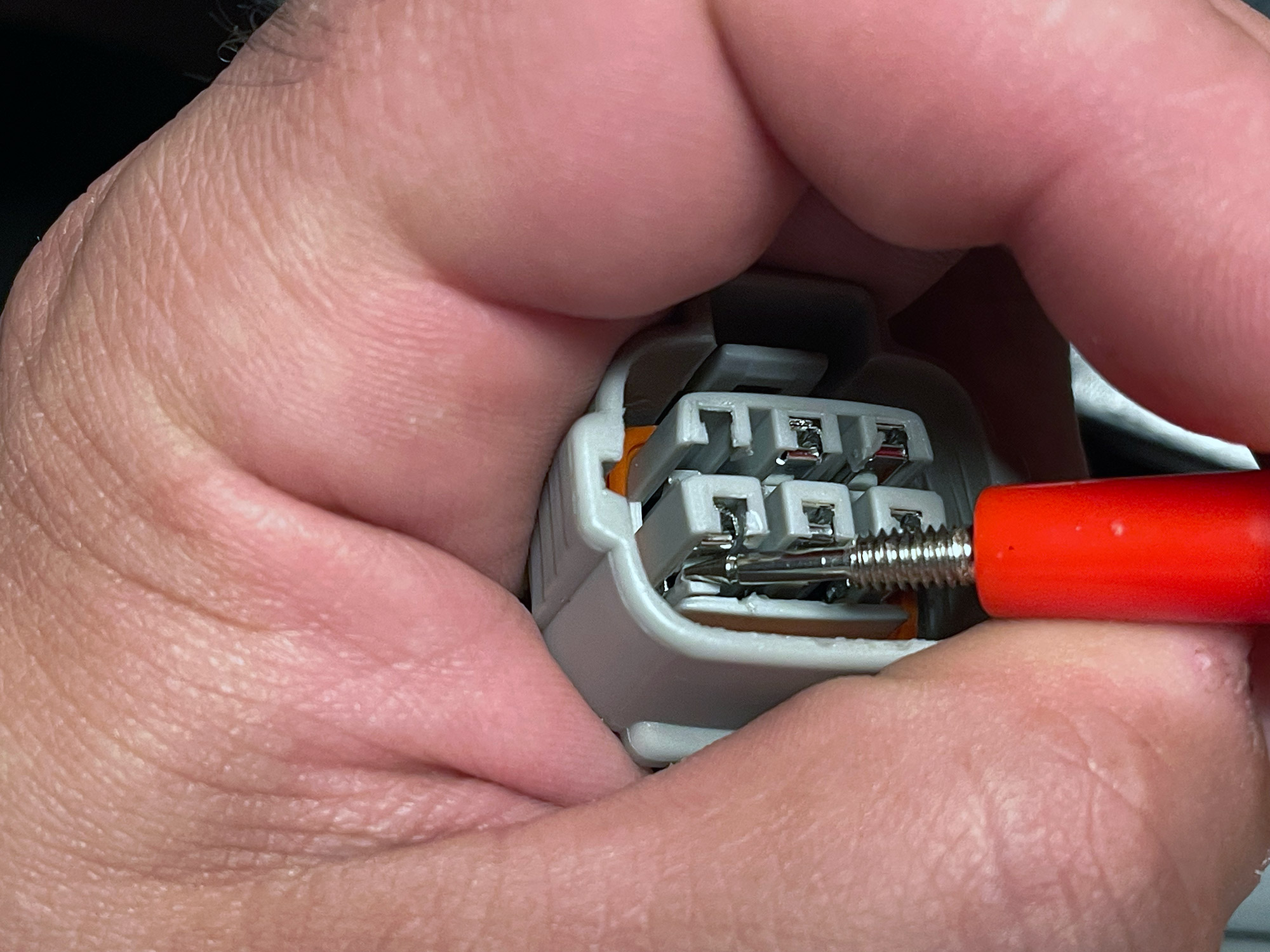
You can make this easier by lightly tugging on the wire for the terminal you’re trying to remove as you release this clip and the terminal will come out of the back.
With that done just put the black wire that goes out to the rest of the spotlight loom connector into pin six (bottom right), and put whatever was in pin 6 up into pin 3. Once both are clipped in then you push the white terminal retention clip back into the housing and everything will be locked back into place.
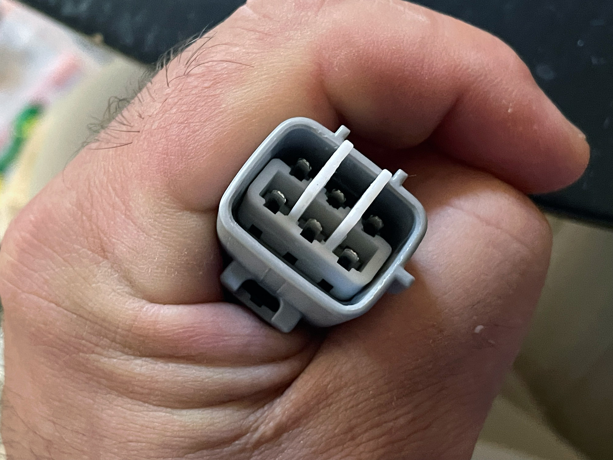
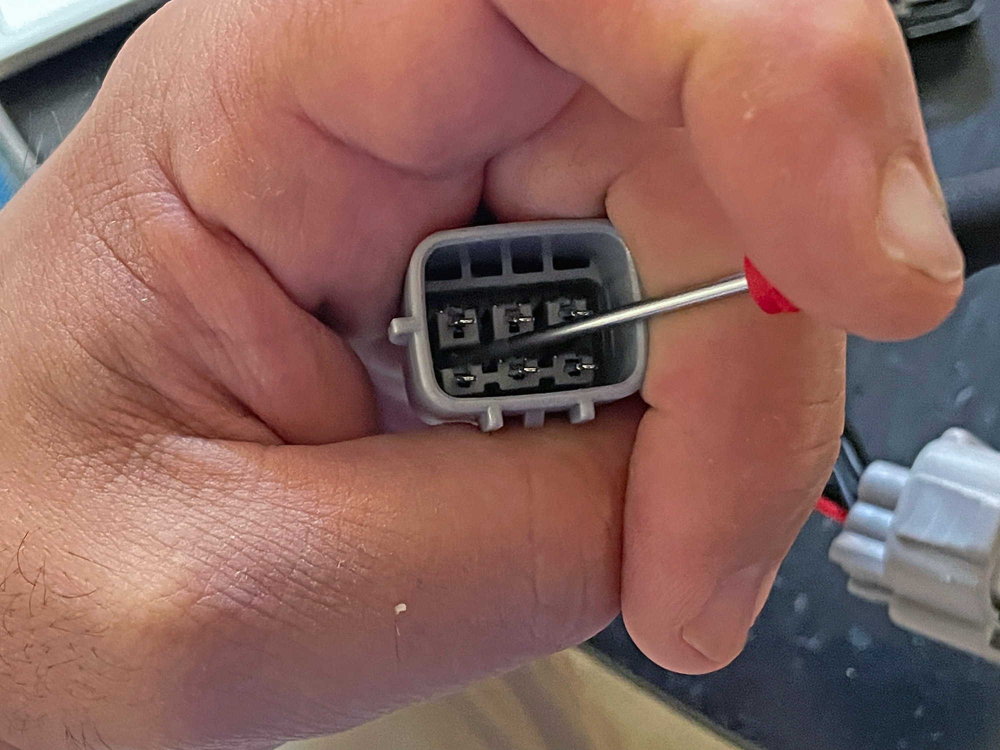
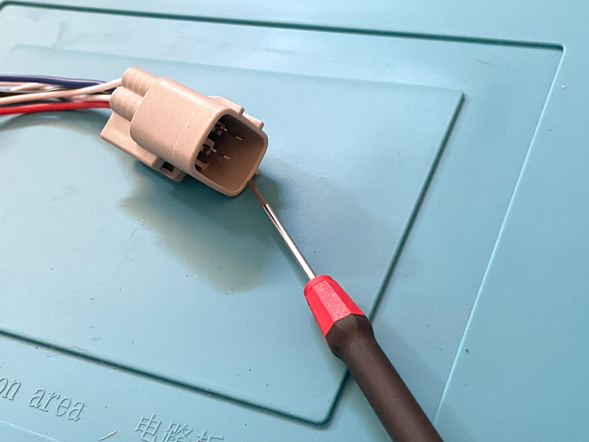
The male connector is a lot more of a pain, and it took me a while to find out how to push out the central terminal retention clip.
I found that I first needed to slightly push it forwards using two holes, accessed above where the wiring goes in. I pushed on these with the smallest jewellers sized flat bladed screwdriver I had, but a depinning tool probably would work better.
This didn’t seem to achieve much, but the central white retaining clip now was just ever so slightly further up off the clips, and I could use a pair of pliers to pull it out of the connector housing. I don’t have a photo of pulling on it with pliers, but just imagine a pair of thin needle nosed pliers pulling on one of the tallest parts of the retention clip.
With that retention clip totally removed, you now have access to the terminal clips themselves. These work just like the female terminals. Just release them with a pick, screwdriver or depinning tool and tug on the wire for the relevant connector.
Release both terminals you want to swap (making sure it lines up with the other housing when connected i.e. pin to pin!) and push the swapped terminals home. You may need to straighten terminals if you bent them releasing the pins, and then push home the central retention clip.
At that point you now have a fully repinned harness which will work correctly.
If the supplier you bought your terminals from wants to charge you to send the old one back then this is going to be your best method to not be further out of pocket.
Making your own
Honestly making your own is a relatively straightforward exercise, it isn’t hard and it will cost you less in bits and even tools than buying a commercial adapter that might not even work correctly anyway.
Sourcing the connectors
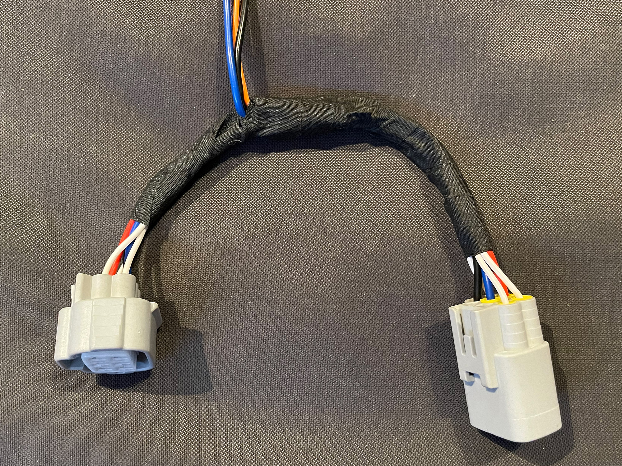
The LED headlights use a sealed 6 pin Sumitomo TS series connector. A piggyback harness requires the male and female connectors: 6188-0175 and 6189-0323 respectively. One end gets the female adapter to plug into the car’s wiring loom, and the other end gets the male connector to plug into the headlight housing.
You can buy these from official resellers of Sumitomo connectors such as Eastern Beaver, or try your luck with non genuine ones from ebay/aliexpress or similar by searching the part numbers. Note that the Eastern Beaver listing has a slightly different part number, I think this is down to the pin sized used (or even the wiring insulation boots) but it does look correct.
In addition to the main connectors, you also need to consider how you are connecting to the rest of your driving light wiring loom. If making it yourself then you can run the high beam positive wire into the cabin as your source of the input to the switch. If you are using a commercial loom then you need to work out what connector is going to suit that loom or cut it and put on your own as you see fit.
If you want to use an open housing T connector like a lot of commercial plug and play looms use, then the easiest option is Narva part 56272BL. This is both the male and female connector so you’ll have more than you need, but it is the cheapest option to easily get one. What is also good is the connector you don’t need happens to be the right one for making a speaker connector for the Jimny though!
Wiring
You essentially wire pins 1, 3, 5 and 6 straight through to the other connector, unless you want the park light pulled out (see below on ARB bullbars) or low beam for some other purpose (e.g. switch illumination). If you want to ground your driving light wiring harness back to the headlight then pin 4 is officially the high beam ground, though note they both join back in the car’s wiring loom to the same earth point so it doesn’t matter if you use pins 4 or 6. Finally, pin 2 is doubled up to a connector to give you high beam signal back to the car for use with your driving light wiring harness’ switch in the cabin to allow you to turn off the driving lights independently of high beam.
Additional segments for ARB bullbars
ARB bullbars also take a park light signal from each side to put into the park light part of the bullbar (half of the indicator on each side in the bullbar). If you are considering an ARB bullbar you might as well also pull out a lead for this light, too. I believe this can then be wired up to a 3 pin AMP superseal connector for the park light/indicator for each side of the bullbar.
How-to guide: DIY piggyback adapters
This is a pretty general guide and I do assume you’re familiar with crimping ‘normal’ automotive crimp connectors e.g. the red-blue-yellow ones. You also have to make a choice about how you’re going to connect to the driving light wiring harness and your choice of that connector will dictate the end steps, and it’s too hard to show all permutations.
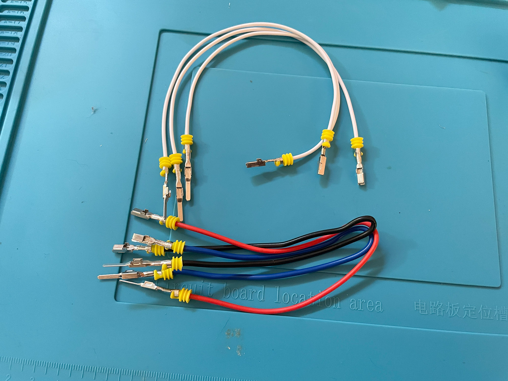
Here’s an image showing you the stuff you’ll need.
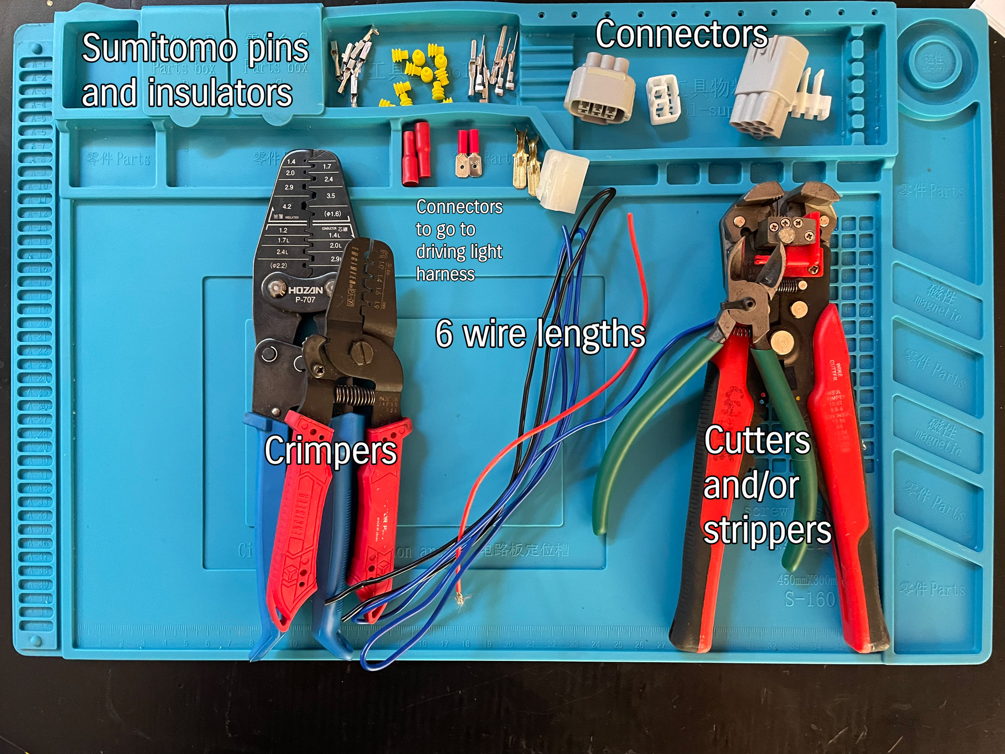
The one I am going to make will suit an ARB bullbar so I pull out ground, park light and high beam. This means 3 wires that get broken out and 3 just get passed through.
There’s a lot of ways to skin the cat making these adapters, personally I like to make wires like they’re all passthroughs then cut the ones that get broken out and join them there. You’ll see this in a minute.
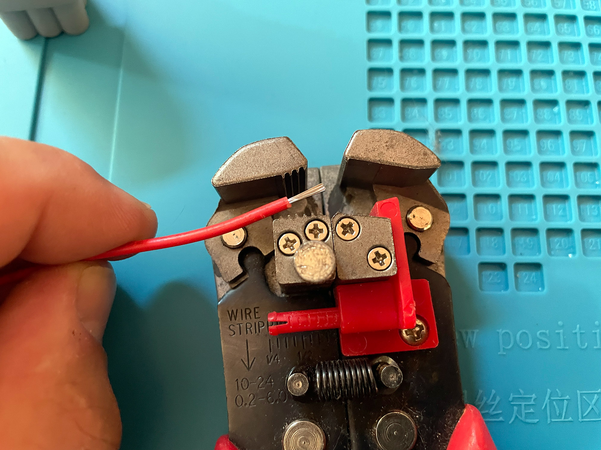
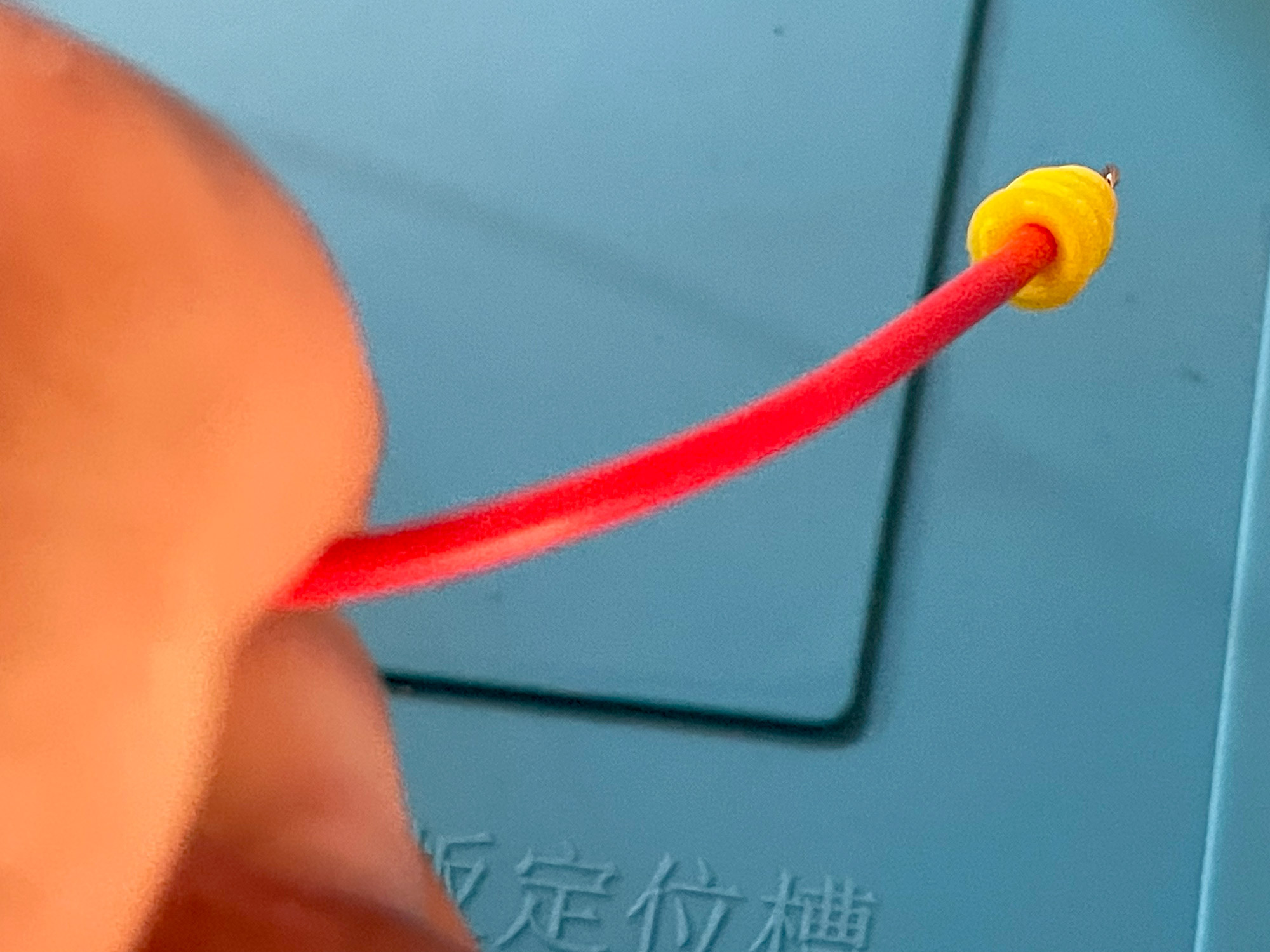
Before then though it is stripping time. You need a little bit of wire stripped, basically just enough to fit into the crimp area of the terminals.
Automatic strippers are great for consistency here.
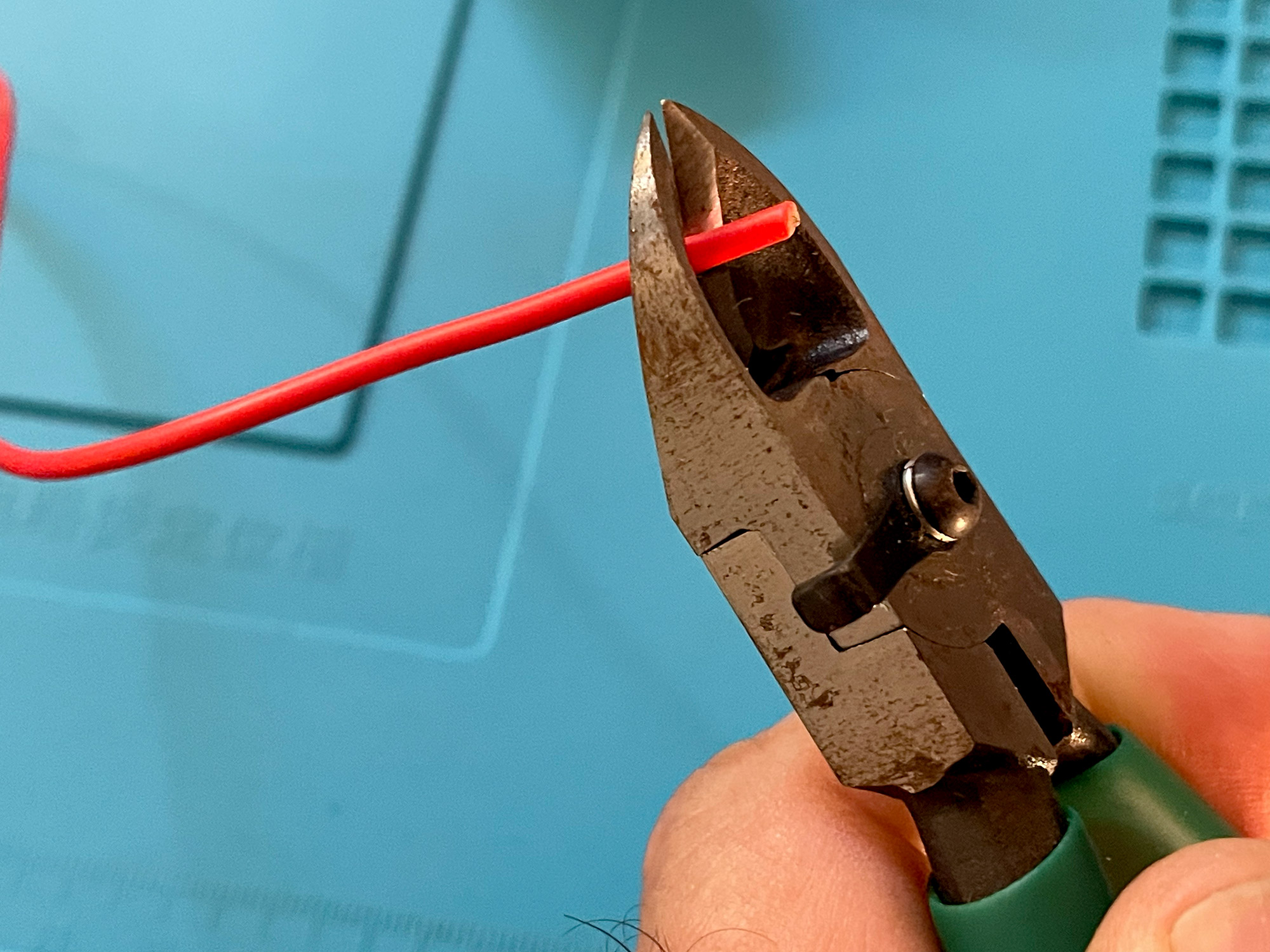
Can totally do it oldschool with some sidecutters and some care though.
With the wire stripped it’s time to fit a connector. Here’s the arrangement so you understand the order before you start crimping away.
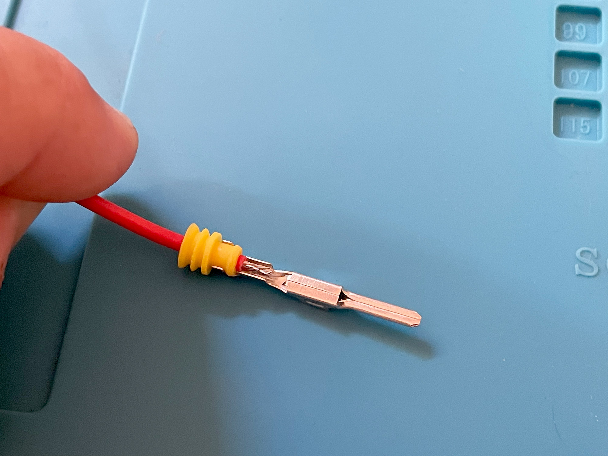
Really good pro crimpers, btw, crimp the insulator rubber and also the conductor part simultaneously; all of the crimpers I use are manual ones where you do one then the other. I always do the conductor first then crimp the insulator rubber onto the wire. Not totally sure it matters what order as the insulator pulls enough on the cable insulation that it stops the wire moving.
Speaking of the insulator you need to make sure you use the right ones for the diameter wire you are using. Often they are different colours and are usually specified when you order the terminals. The rubber should be just slightly tight against the wire insulation, you don’t want any gap as it’s the primary waterproof sealing here; you also don’t want it too tight as it’ll bulge and won’t go into the connector housing correctly either.
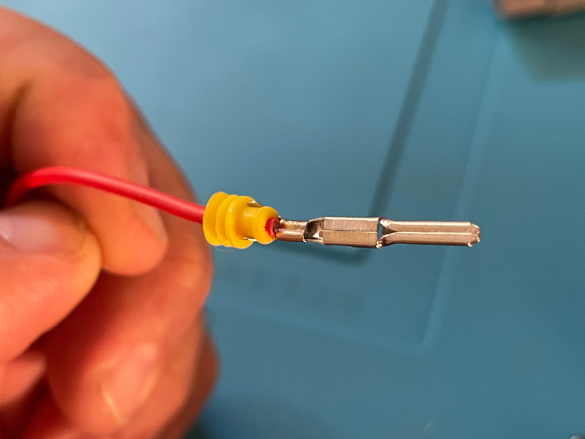
Now it’s crimping time. The exact position/setting/whatever will depend on your crimper and the wires you’re using etc. You’re looking to neatly fold over the two sides of the crimp part and trap the wire and insulator without crushing it. It can be worth having some extra terminals on hand to test what settings you need. Note you can do this part with absolutely super basic uninsulated terminal crimpers, it’s just a case of going slow and making sure you have a nice good crimp before you move on.
Here’s what a good (enough) crimp looks like, before moving onto crimping the insulator onto the wire.
Repeat the process to crimp the insulator on. Repeat on the other end with the other type of connector and you’ve made up one of your 6 wires.
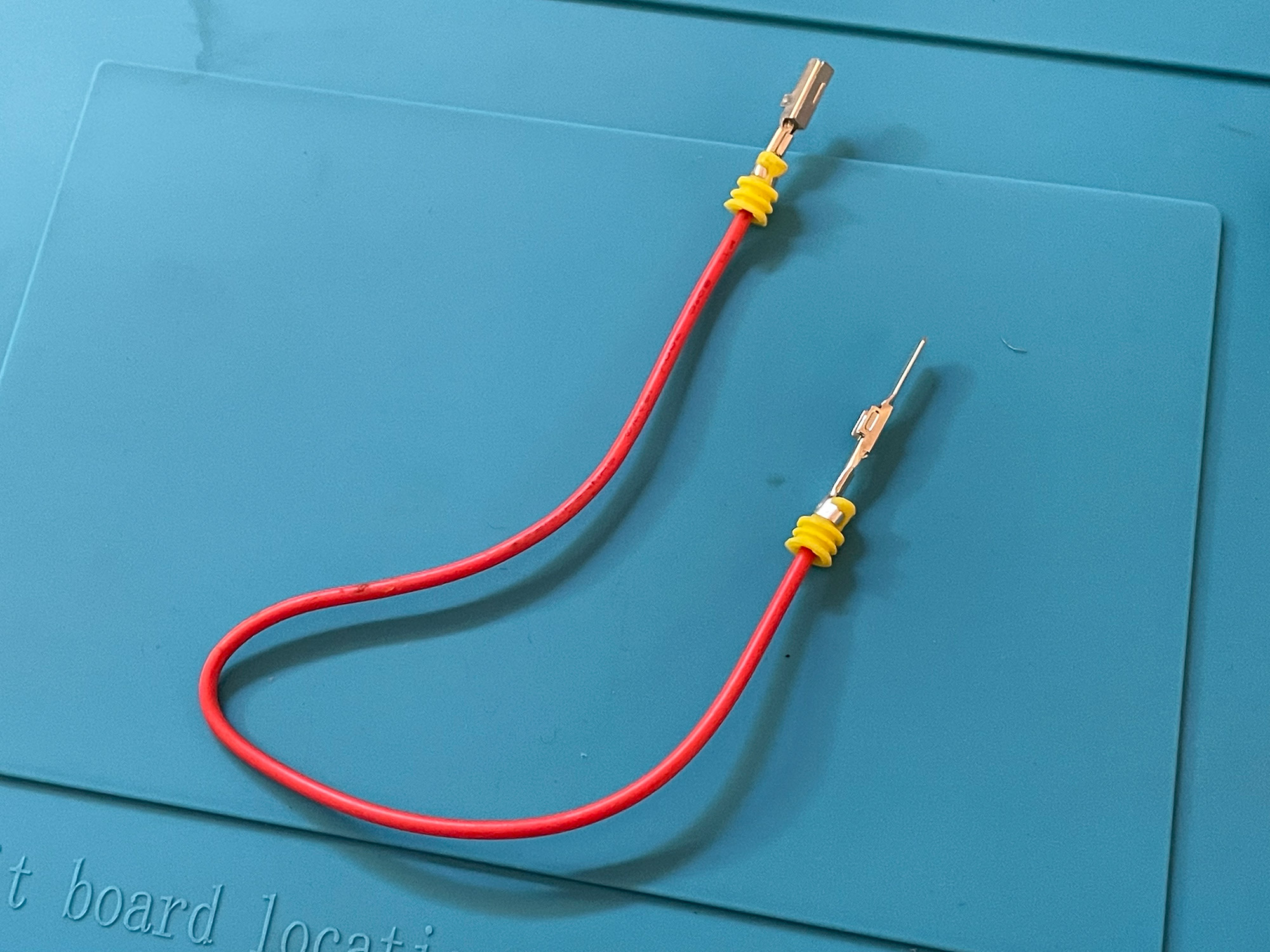
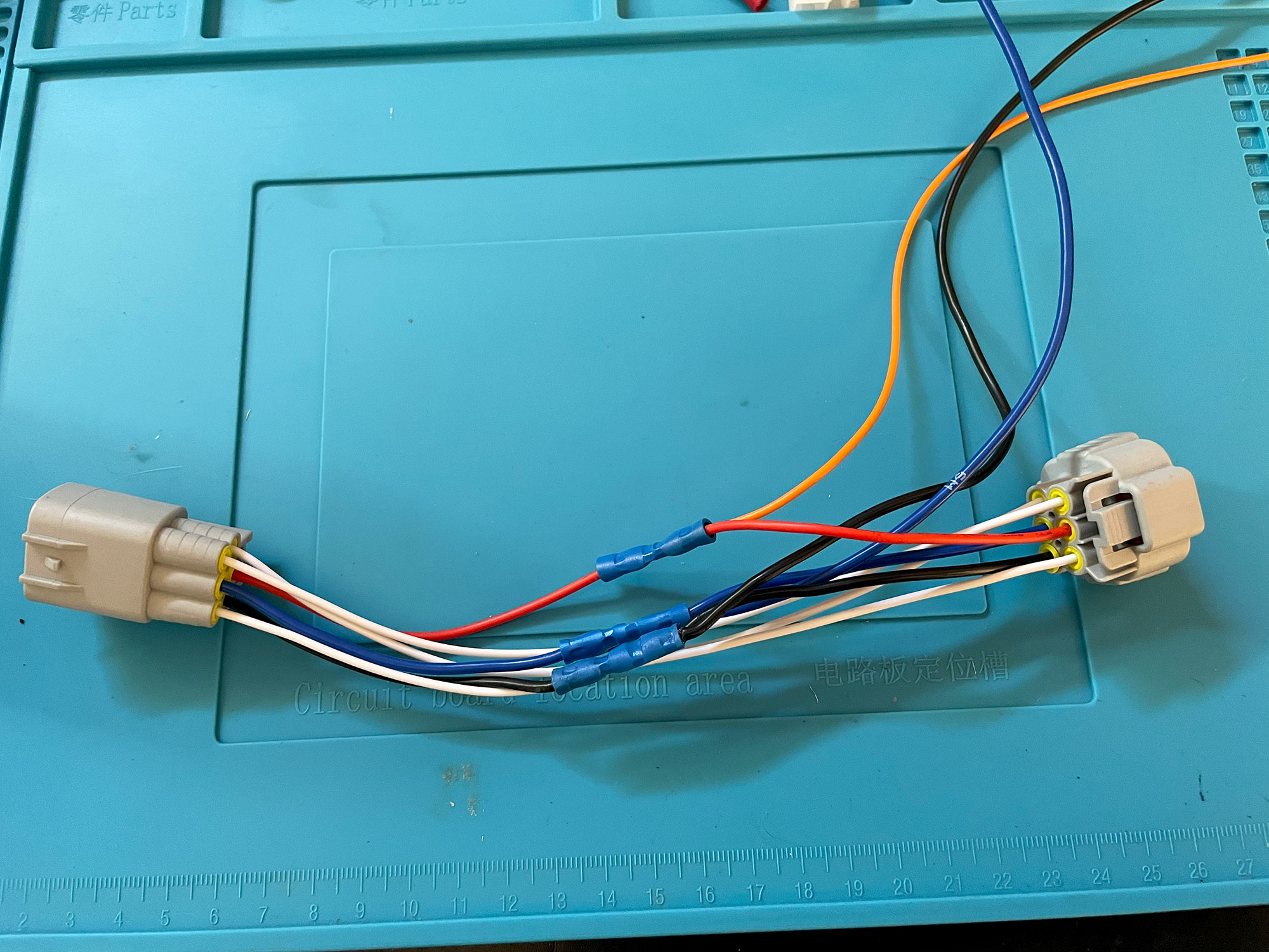
Do this 5 more times and you’ll have 6 wires, with a male and a female connector at either end. The coloured wires below are folded in half to work out where I want to do the breakout part for the wires for the piggyback.
To help me get my head around where all the wires will run, I first put all of the passthrough wires into the two connector halves. With these Sumitomo connectors, the connector with the handle for the clip gets the female connectors and the slightly smaller connector without the handle gets the male connectors. You just push them in till they click into place. They won’t easily go in upside-down, so you’ll quite easily get the orientation worked out.
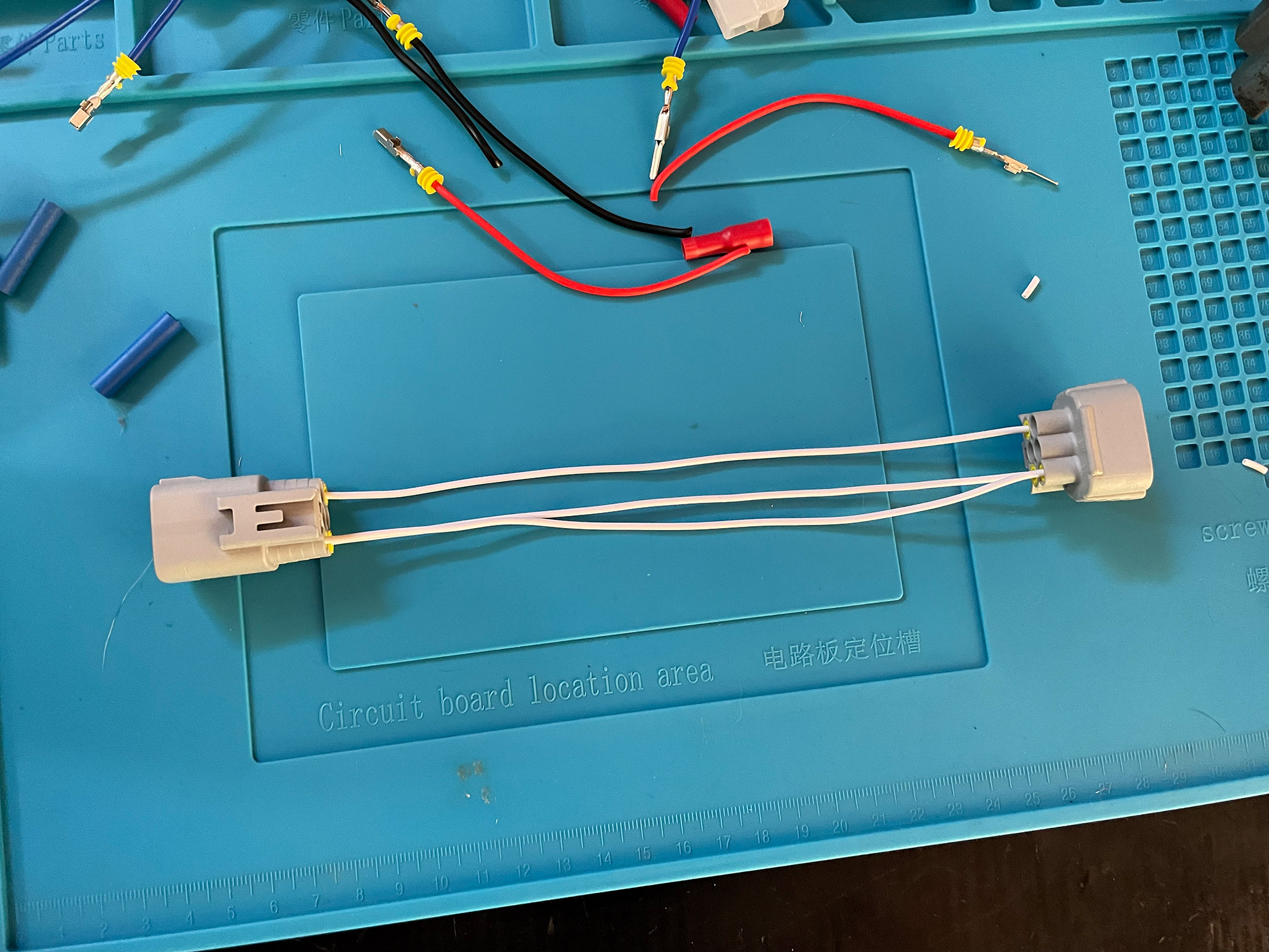
Now is a good time to talk strategy of the joining of the two sides on the wires you are breaking out. Many manufacturers of these commercially just put each side of the lead you’re breaking out into a connector and crimp it, a la the following image.
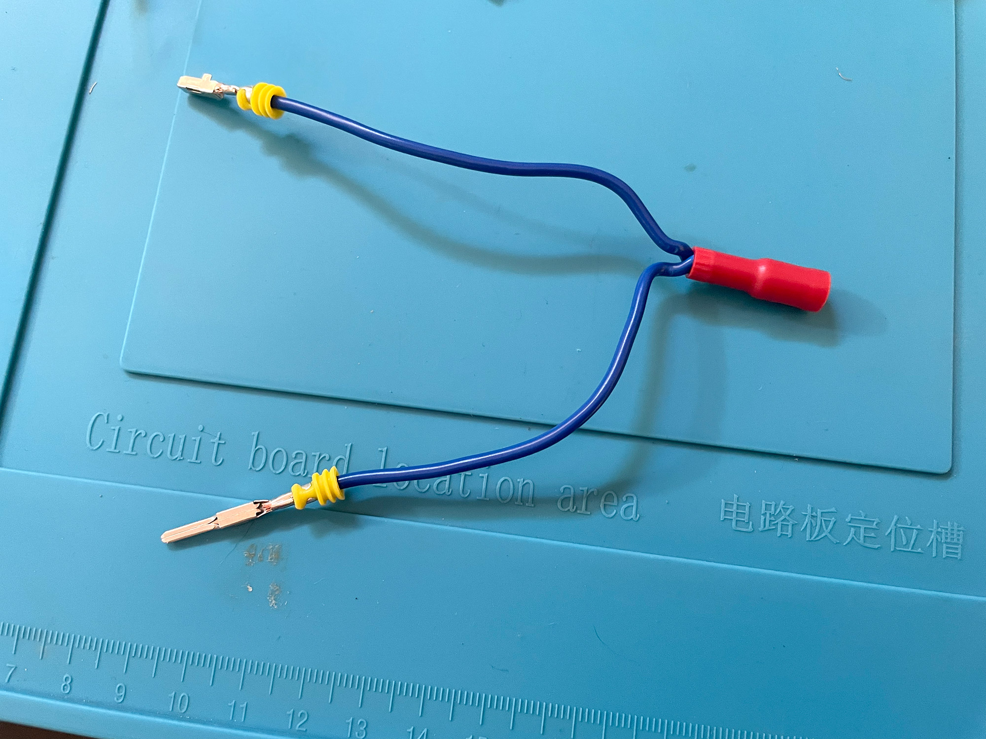
I don’t like this as potentially if your connector fails at the end then you’ll lose a fairly important light signal e.g. high beam. I prefer to join another wire on. You’re basically just joining another wire to where you’re joining the two halves of the wire you want to break out, a bit like this following image.
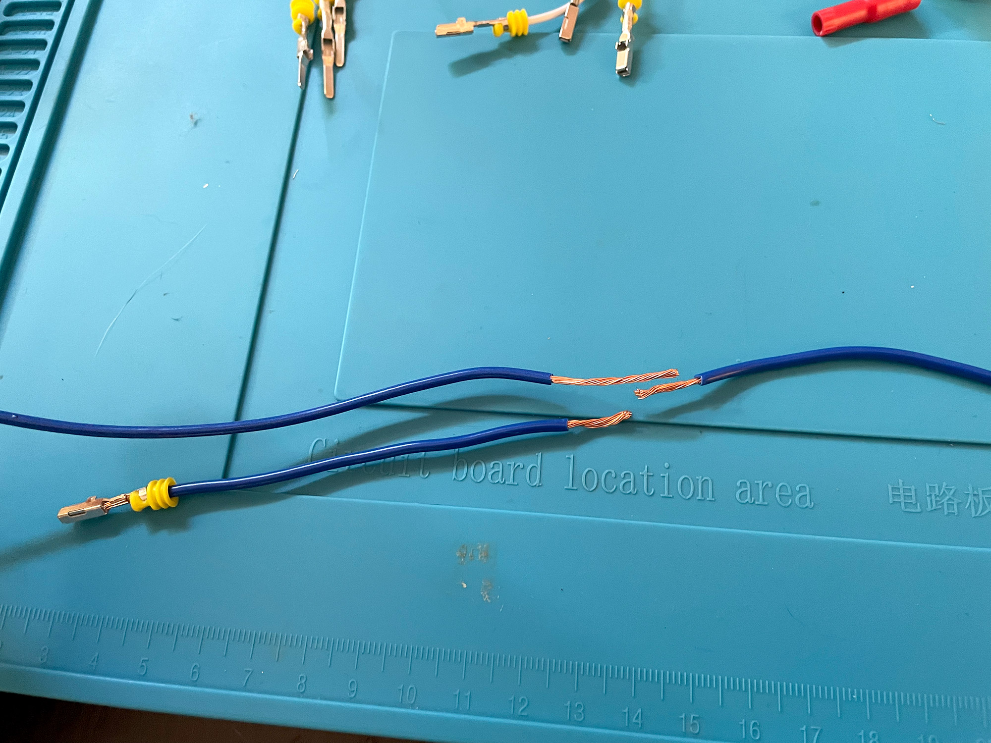
While this does still have a potential point of failure, it’s a lot harder for it to totally lose connection in one go with one wire. There’s multiple ways to join these wires with soldering and the like, but butt crimp connectors are a good way to go. Often I’d use an uninsulated one and some heatshrink, I didn’t have any handy so just used normal automotive insulated ones here.
Here’s what that looks like poked into a butt connector. Poke in the side where the breakout wire connects, then push in the single other side to get it all laid out nicely.
With these crimp fittings just use the regular automotive crimpers. I have a nice pair of ratchet crimpers which aren’t expensive, and well worth getting. With the terminals crimped you’re now ready to assemble the connector entirely.
Now you can go through and put all of your other wires into the housing in their correct spots.
However, if you’re like me, you’ll get this wrong. One of the great things about making stuff like this yourself is you can verify the wiring before pushing in the white terminal retaining clips. This makes it super easy to depin and move pins around: just use a small flat bladed screwdriver to release the relevant terminal and swap it around.
Make sure wires line up correctly with each other when you plug each end of the piggyback into each other. In addition you should also check it against the wiring diagram shown at the top of this article, too.
With the wiring all checked off and you’re happy with everything, you can push in the pin retaining clips to their respective housings.
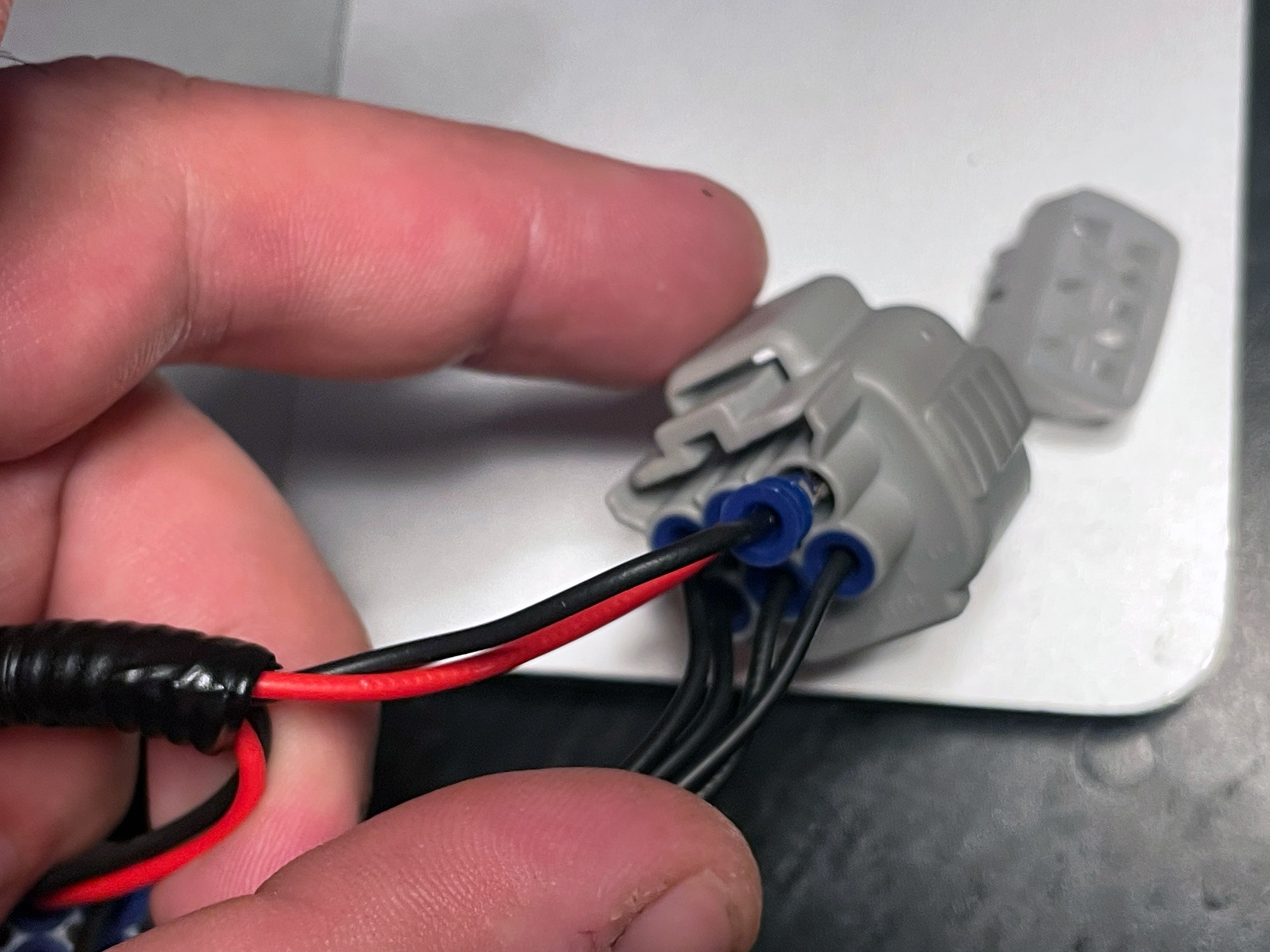
And with that just time to tape it up and make it look professional. I am actually terminating my wires into a relay box without any further connectors, but obviously you’d add whatever connectors you need to go to your driving lights harness at this point too.
Happy days. All sorted, and they’re honestly not hard terminals to crimp even using cheap $5 fixed crimpers.
As a bit of a bonus wrapup for this, here’s some suggestion of tools or other things to get:
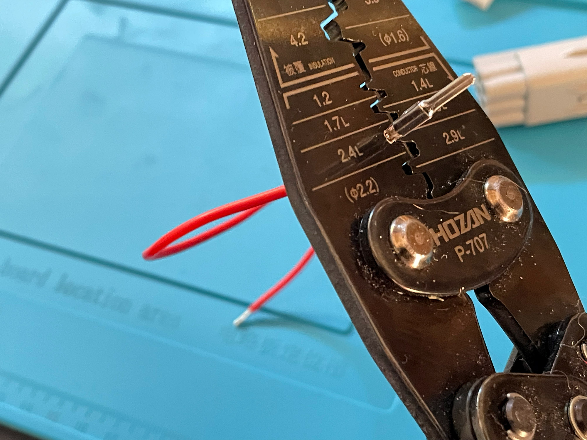
- Crimpers: you probably can get away with using the universal crimpers from Jaycar. I like my Hozan P-707 crimpers, though. Engineer crimpers, like the PA-21s which probably cover the right range for this work, used to be cheap but they’re not far off the Hozan crimpers now. The Jaycar crimpers that take replacable dies probabaly would work with their Deutsch connector dies.
- Cutters/strippers: the universal automatic strippers are great and you’ll get heaps of use out of them. They probably would also do in a pinch for the crimping tasks. I’m a big fan of nice dedicated precision electrical side cutters for this sort of work, too, if you want to add them to your toolbox.
- Tape: Tesa electrical loom tape is the only choice here worth making. It never goes sticky and weird, it copes with high temperatures and it basically makes your looms look and feel like they’re 100% professional quality.