
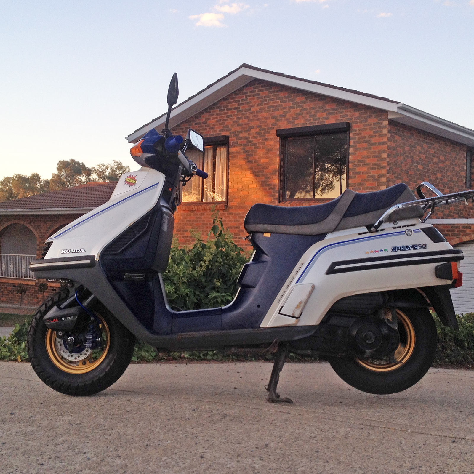
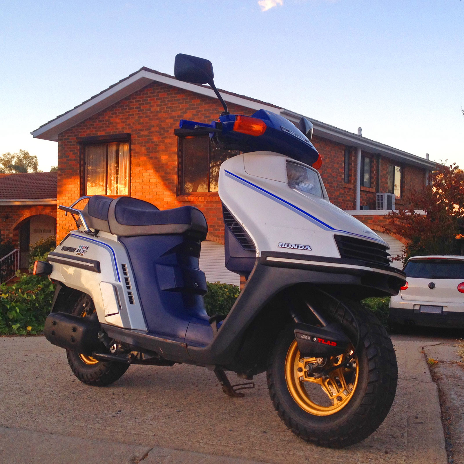
1987 Honda CH250H Spacy “Kevin”
This is the story of Emma’s Honda CH250 Spacy scooter – a 1987 model, Australian delivered so that means a front disc! Read on for how we rescued this little oddball scooter.
Where we are now with it
(02 April 2016)

The purchase
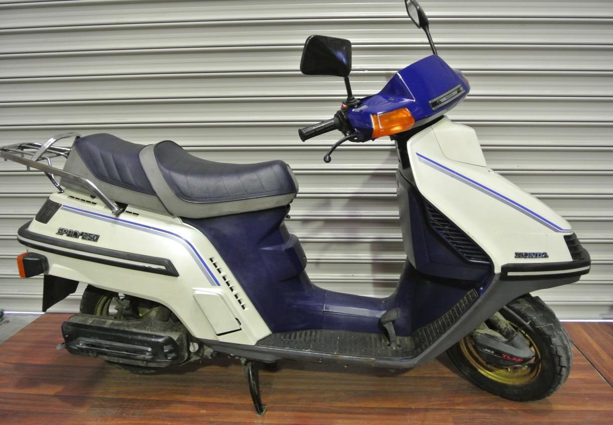
Kevin comes from an ebay auction for his fate. Emma won him, and dragged him back from a life by the sea slowly corroding in Sydney.
The initial repairs
Initial repairs – without pics, were to clean up the bodywork and get him running. A new coil was required, and the carburettor was full of actual sand. With that cleaned out, sorted.
Air filter: 17211-KM1-770 or HiFlo HFA1202
New spark plug: DPR6EA-9 helps with starting too :).
Wheels and tyres
Kevin’s life by the sea resulted in some pretty hectically corroded parts. The wheels especially were bad with huge rust bubbles. Normally I’d just source more wheels but these are 2 piece wheels (inner plus sealed rim), and the outers were the worst part. Problem is that getting them from overseas is not cheap – and a whole wheel from overseas is likely to be a front drum setup, which necessitates the changing of the front suspension from this Australian delivered version with a front disc.

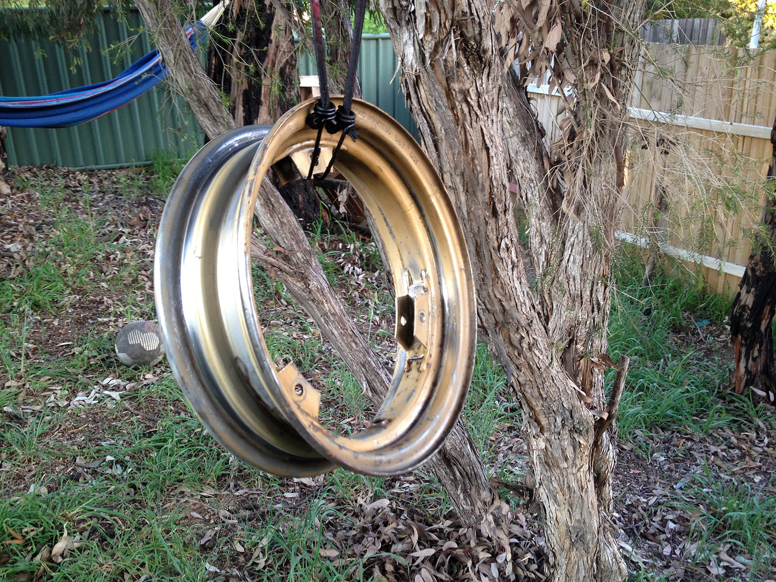
The start of the wheels at the start. At first I just wanted to get the tyres off and the wheels apart to clean off the paint and rust and see how deep it goes. You can see one of the bolts for the two part wheels here.
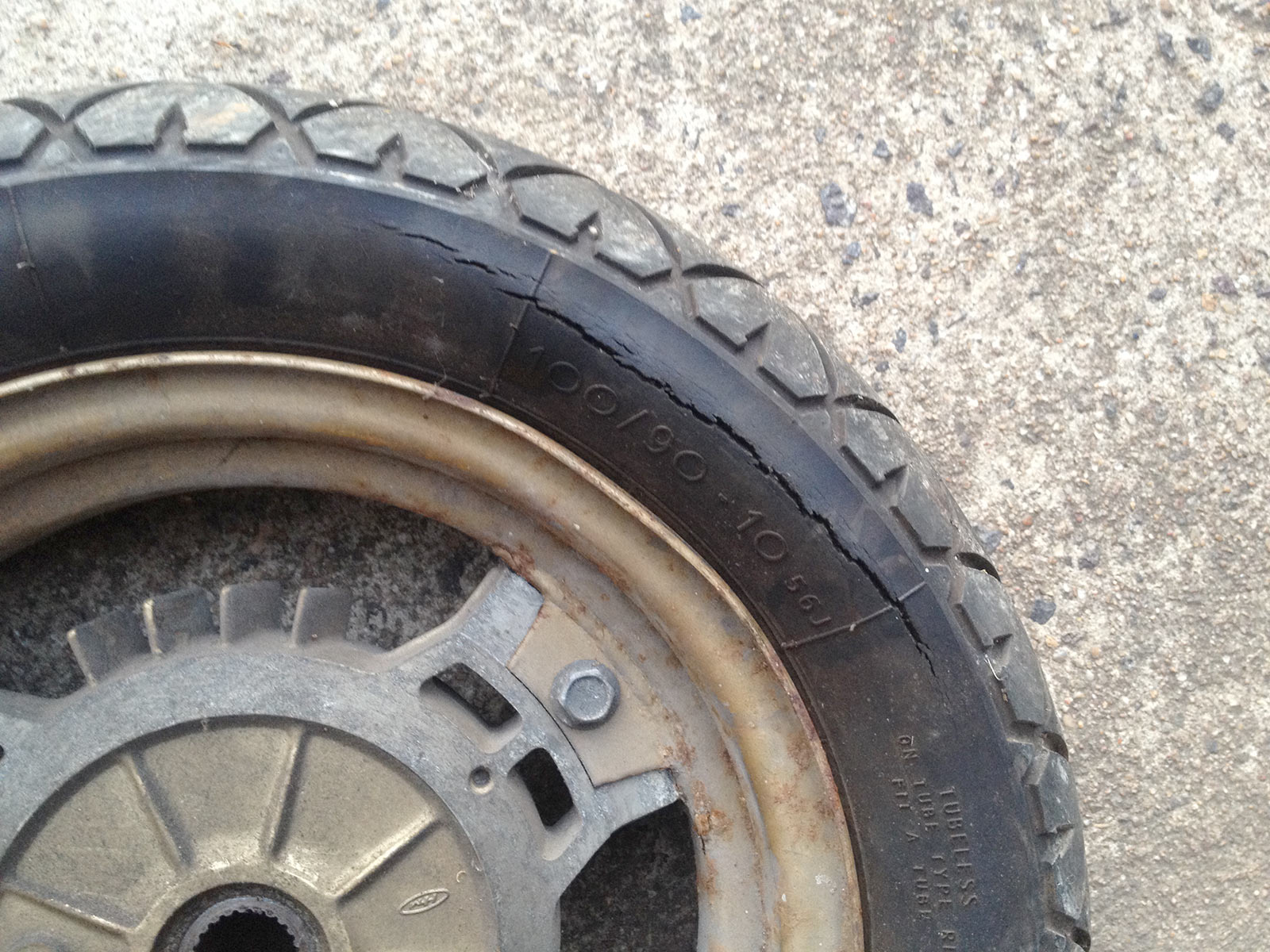
Old, old tyres. These were tyres made in 2002! so they had seen better days. Rolling Kevin around on deflated tyres was pretty annoying.
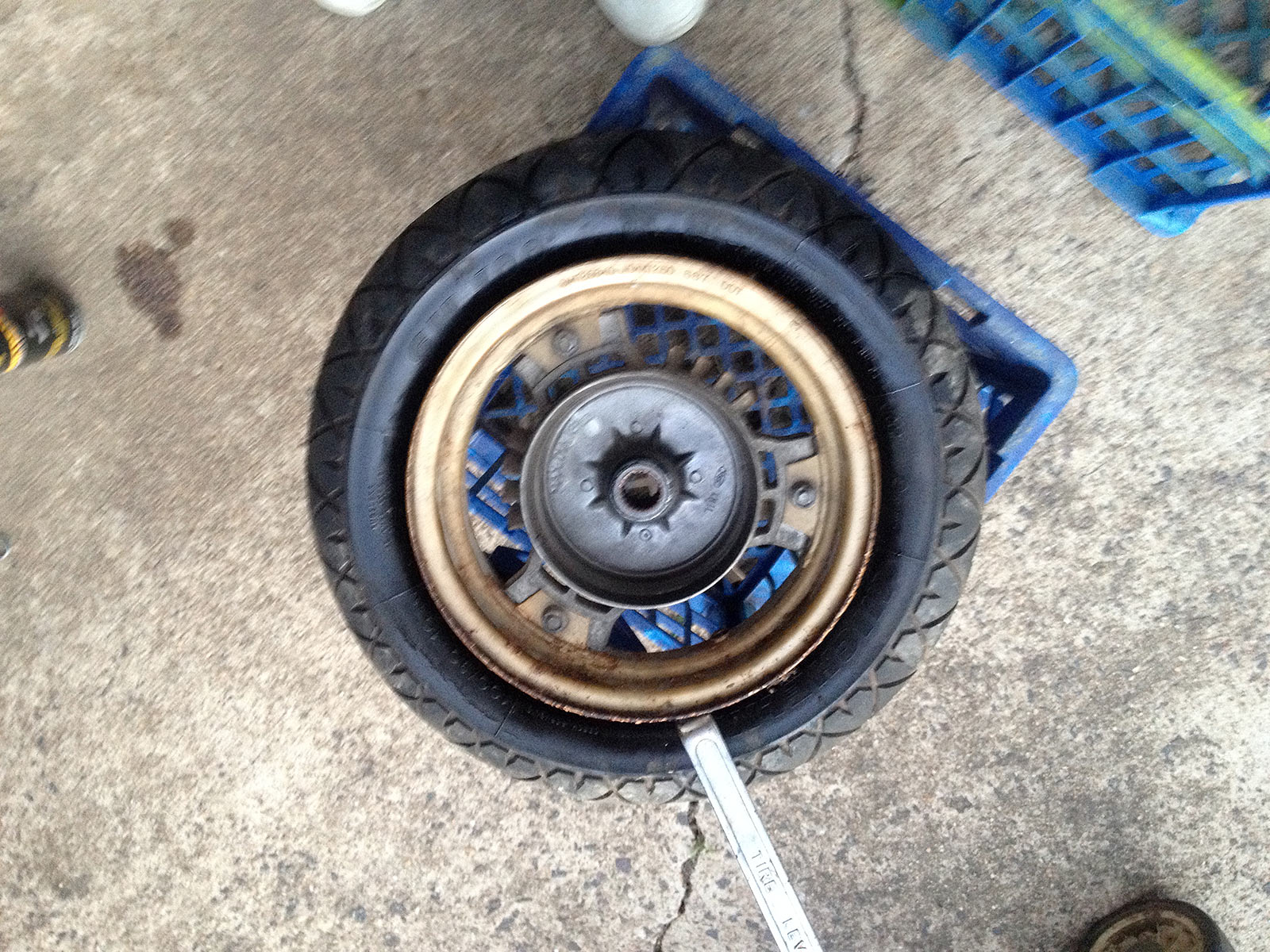
Horrible job but doable at home. The beads were rusted on, but putting a block of wood onto the edge of the tyre and smacking it with a big hammer helped. After this it was just a case of carefully levering the tyres down then up and over the side.
Undoing wheel bolts. They come apart pretty easily normally, however, these were rusted together solidly. With the bolts out, I then had to tap the centres around slowly – they were corroded to the rim outer mounts. Painful.
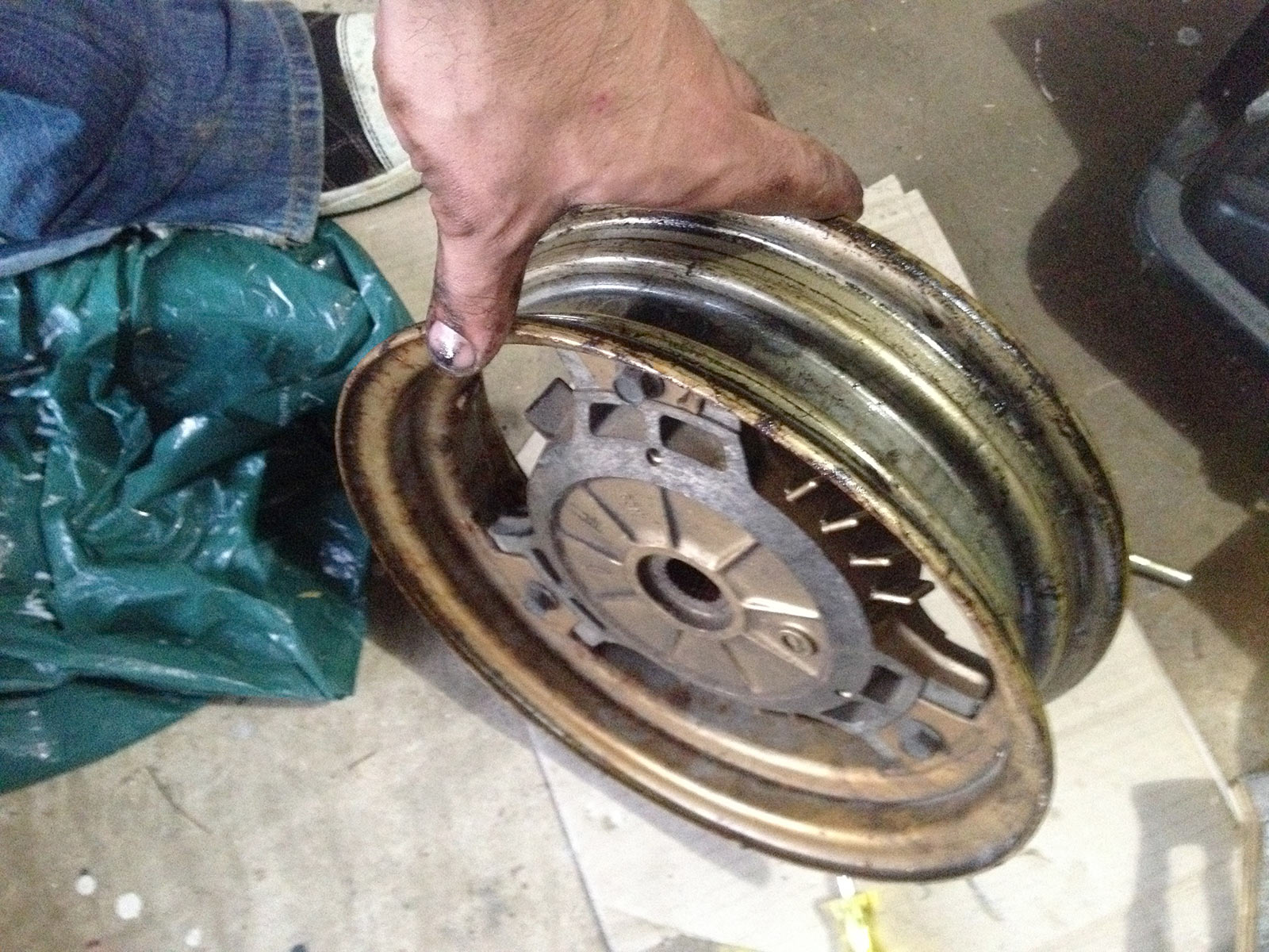
This shows how you rotate the wheel centre to get it out.
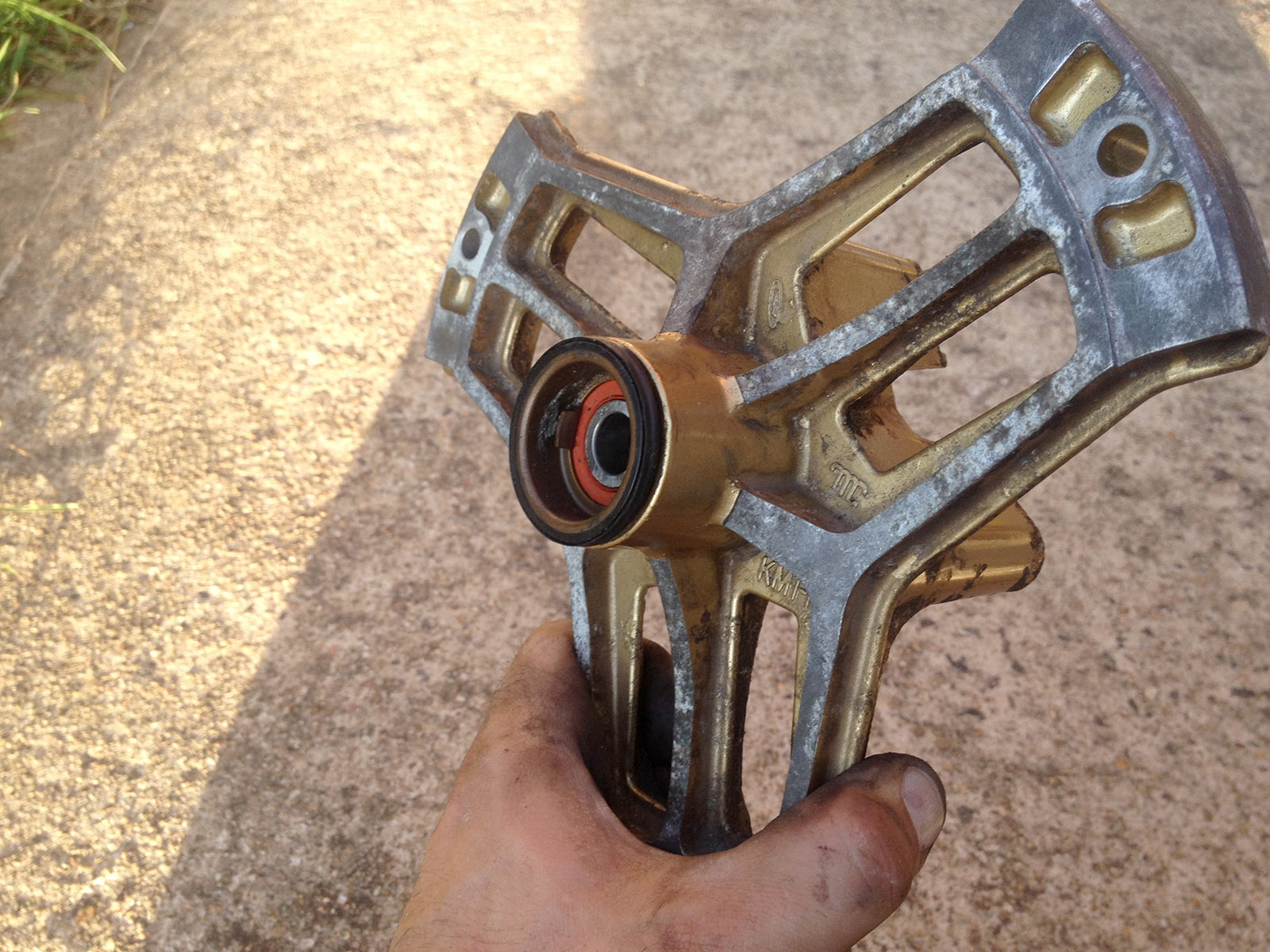
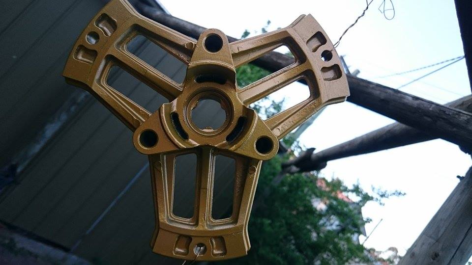
Small amounts of corrosion on the wheel centres (aluminium), but nothing compared to the steel rims.
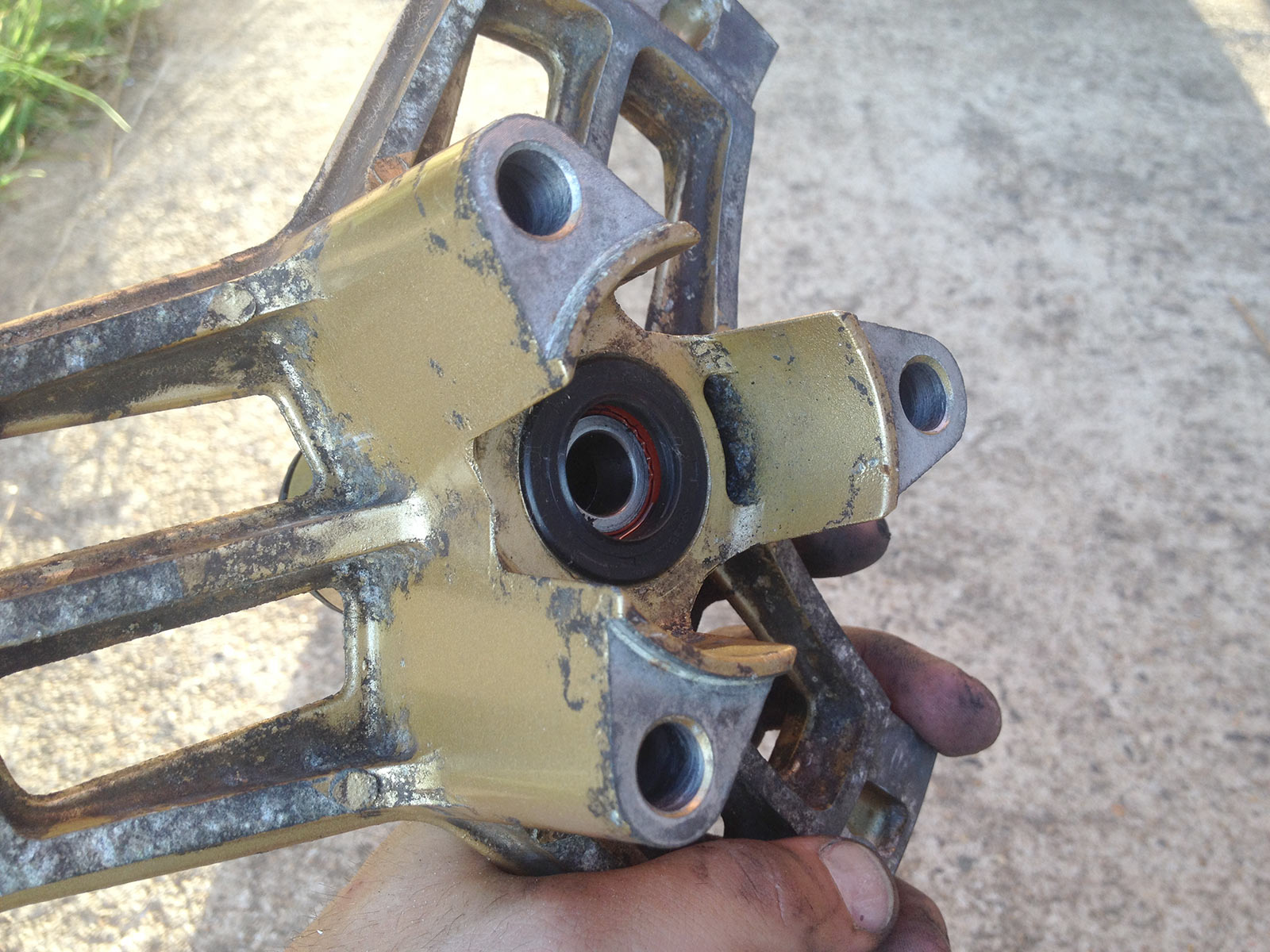
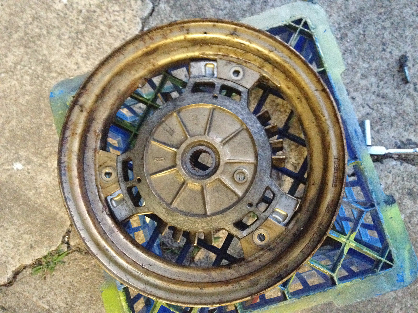
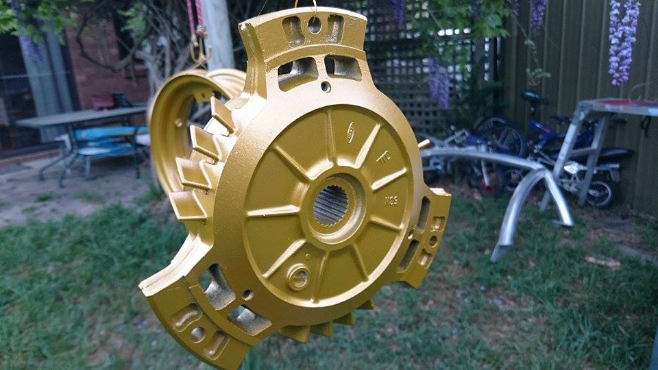
Another shot of the corrosion on the alloy wheel centres. This is the front centre with the mounting point for the disc.
Lots of time on the wire wheel on the bench grinder, a variety of flap discs and other wheels and the corrosion was gone. Thankfully it was all surface stuff. Time wise it would have been more efficient to get the wheels blasted, but I wasn’t sure of the integrity so the wire wheeling was first to see if I had something salvageable. Turns out I did, so I just finished the job.
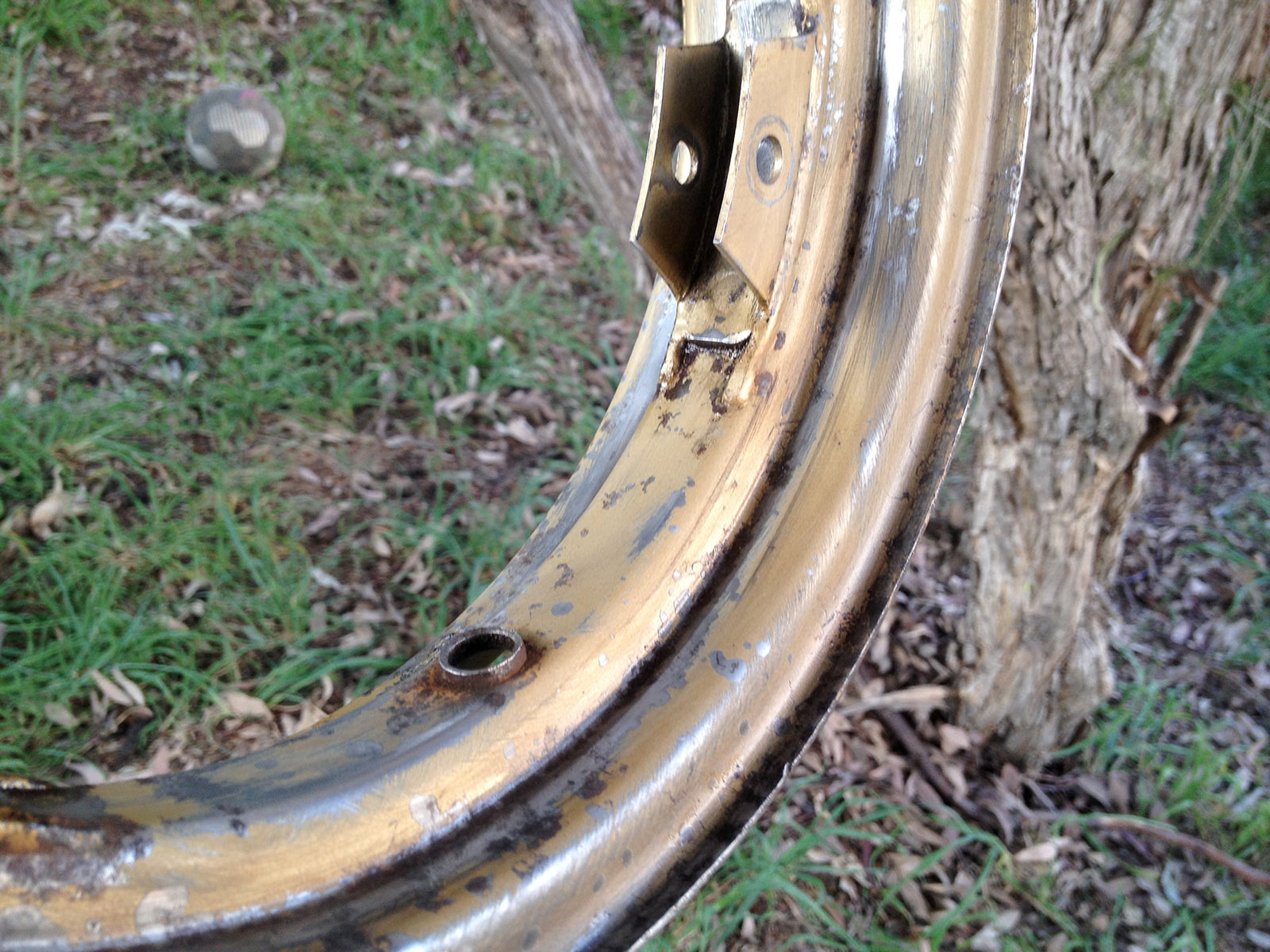
Corrosion-be-gone! No products used on this. Citric acid would have been great, but nope, just lots of time with a wire wheel.
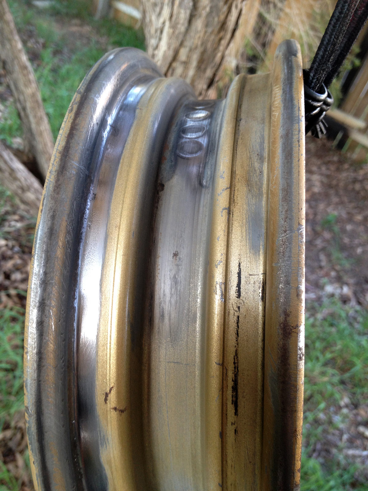
The amount of corrosion underneath the beads was amazing. They wouldn’t have seated very well had these not been cleaned up and then sanded smooth!
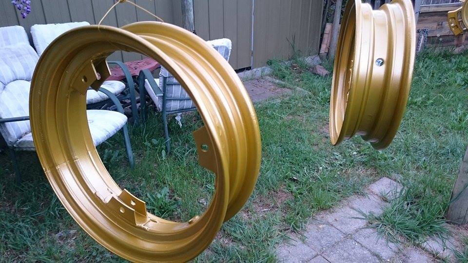
Painting the wheels. Just using some nice shiny gold metallic stuff on top of an anti-rust primer. Beaaaautiful.
Wheels look a million bucks after painting.
So much better.
Needed to sand off the mounting flanges and stuff but that was no biggie. Powdercoating would have been painful with the drive flanges, the inner splines etc. Paint’s a much better option here.
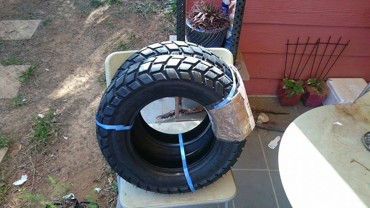
Tyres! We had a few options for retro looking tyres in 4.00-10, but ended up settling for these awesome SL60 Pirelli dualsport scooter tyres. Kevin wears stompy boots.
Running these with tubes, too. Normally a Spacy has wheels with these cool 90 degree valve stems, but they’re a hard to get size and I was impatient. Problem is you gotta find tubes with 90 degree stems, and they are a prick to fish through the valve hole in the rim. I first bought straight valves thinking I could just use 90 degree adapters to fill them. That works on the front with the disc but the back with the drum? No chance.
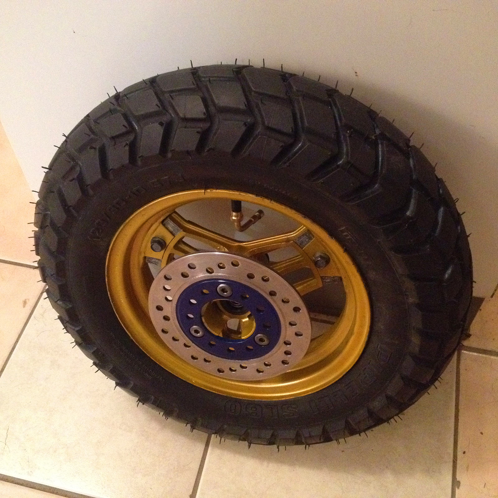
That’s a preview of the disc work to come 🙂 but that’s what they look like assembled (with a straight valve and adapter for filling). Awesome. I did swap to 90 degree valve stems later.
Front wheels needed new seals (along with bearings). Speedo drive seal is part 91258-KM1-004, front wheel seal 90754-GC8-005. Front bearings 6201-2Z (or -ZZ) from any bearing place. Note that means they come with the awesome metal seals for lower drag. If you want longer lasting rubber seals, 6201-2RS.
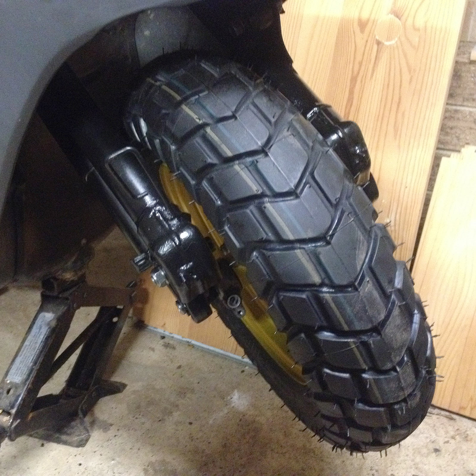
In the bike they just fit, too. 120/90-10 is a bit wider than a 4.00-10, and the tyre juuuuust rubs on the suspension link arm for the anti-dive with the disc arrangement. I believe the different linkage means they’d completely clear the front drum suspension arrangement for the overseas reader.
I had a bit of help fitting the 90 degree valve stem tubes.
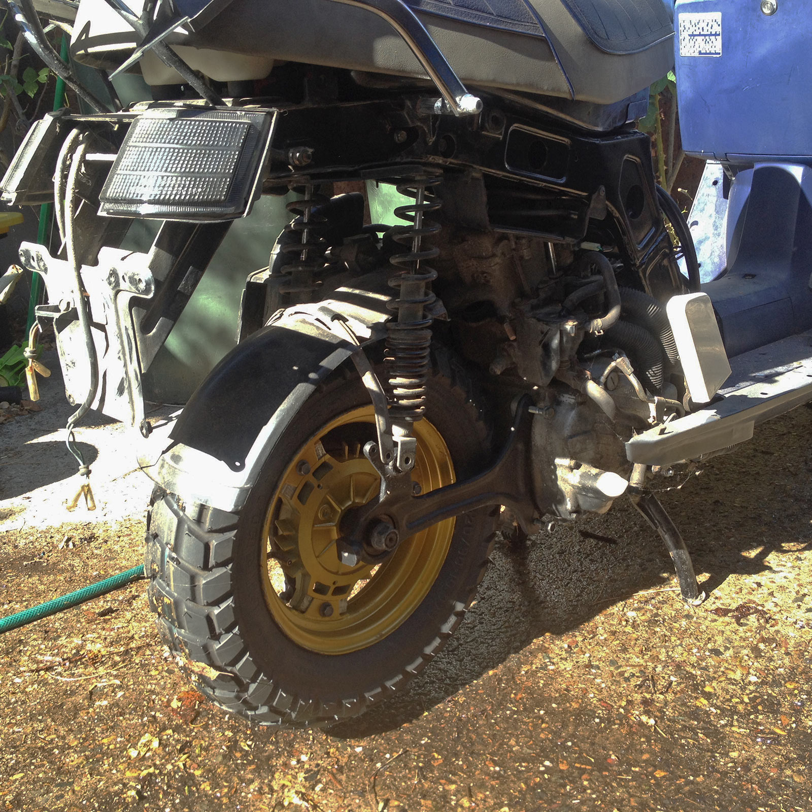
The back clears everything excellently. I was actually more worried about the rear fitment, but it fits just fine with the shocks, rear mudguard etc.
Brakes and suspension
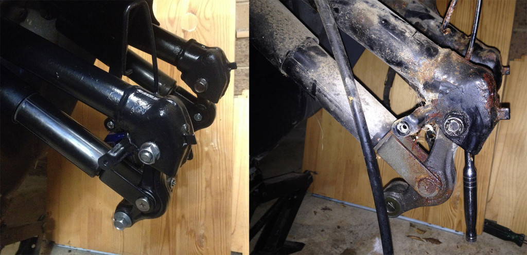
Oh the suspension was bad. The ‘fork’ arrangement with the trailing link setup was hugely rusty, although the rear swingarm was also unhappy. Lots of oxy and impact driver time to get everything apart.
Initial startup indicated there was a massive horrendous noise from the back end – probably why Kevin was parked up, in fact – so the suspension work started there.
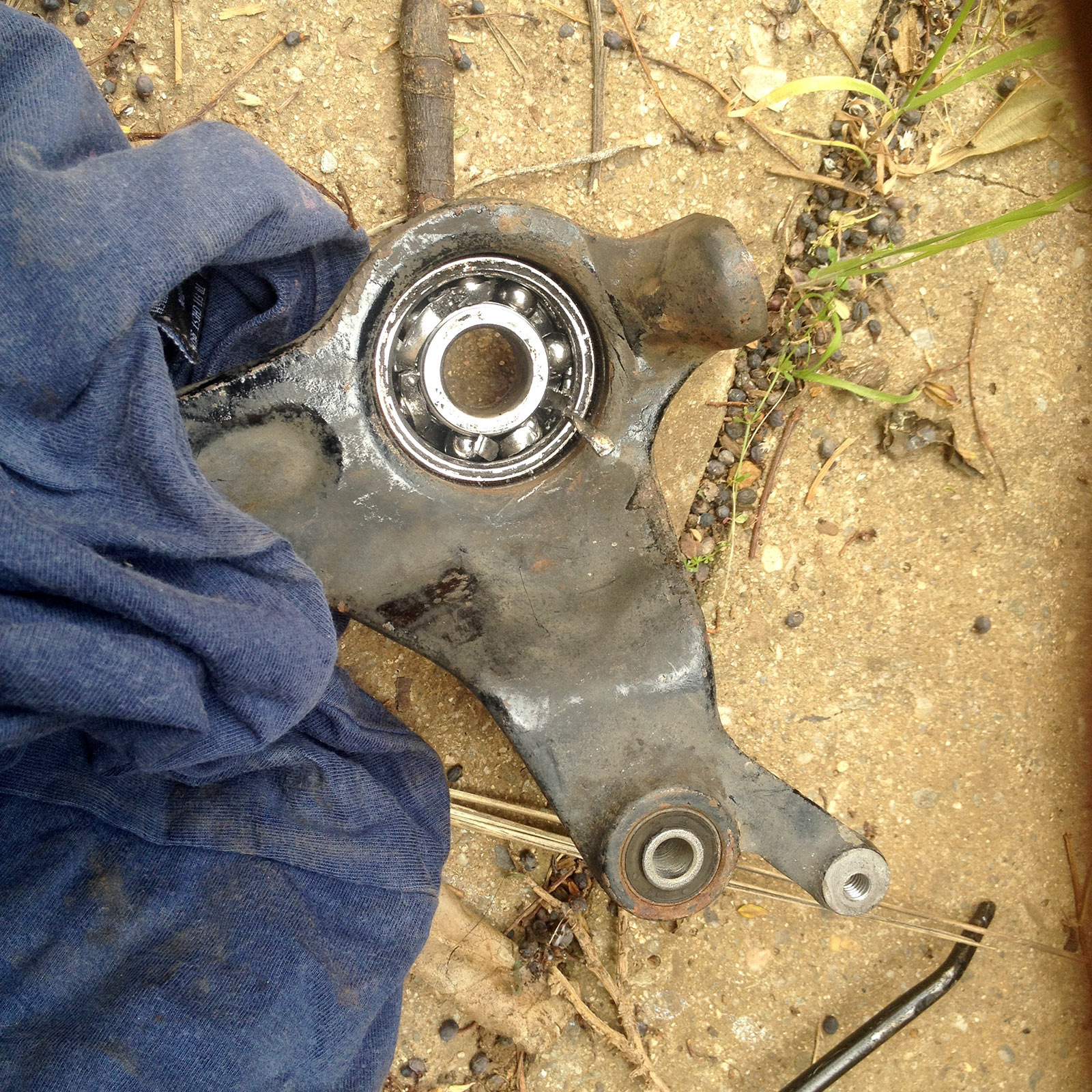
Pretty obvious issue once the seals were removed: the rear wheel bearing in the ‘swingarm’ had completely collapsed. They’re a tight fit, but able to be got out with a bit of heat and a suitable drift.
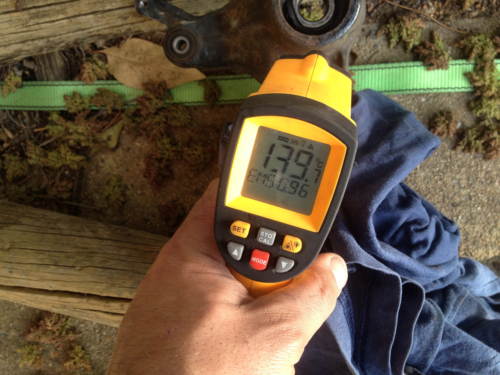
Warmth is good. With that sort of temp it slowly came out. Cleaned up the hole, threw in a new bearing ($5 from a bearing shop: 6303-2RS) and 2 seals direct from Honda (91259-KM1-003).
With that sorted & swingarm painted we can turn the attention to the front trailing link TLAD setup.
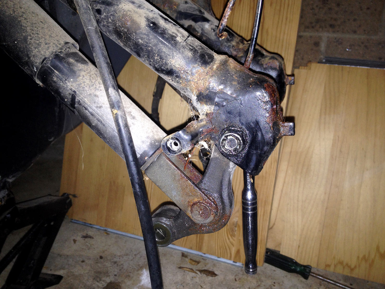
So much rust. Lots of penetrene, lots of reducteur, lots of impact driver action to smack the bolts free. Also a fair bit of blowtorch action to heat things up. Got them all out though, phew… didn’t lose a single bolt. Probably good, cause they’re all special weirdo flanged or shanked bolts and would need to be sourced OEM.
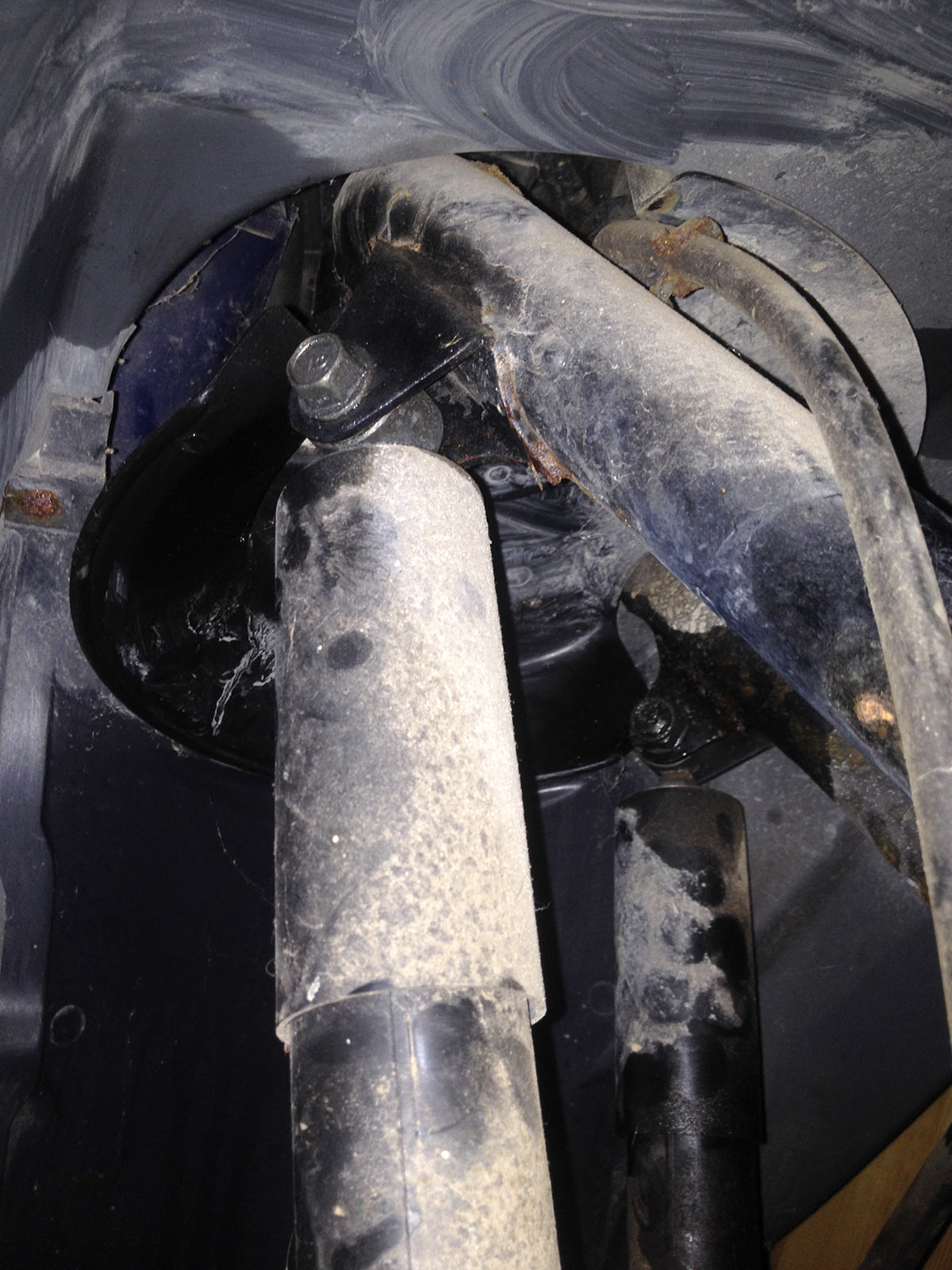
Everything, and I mean everything, was stuck.
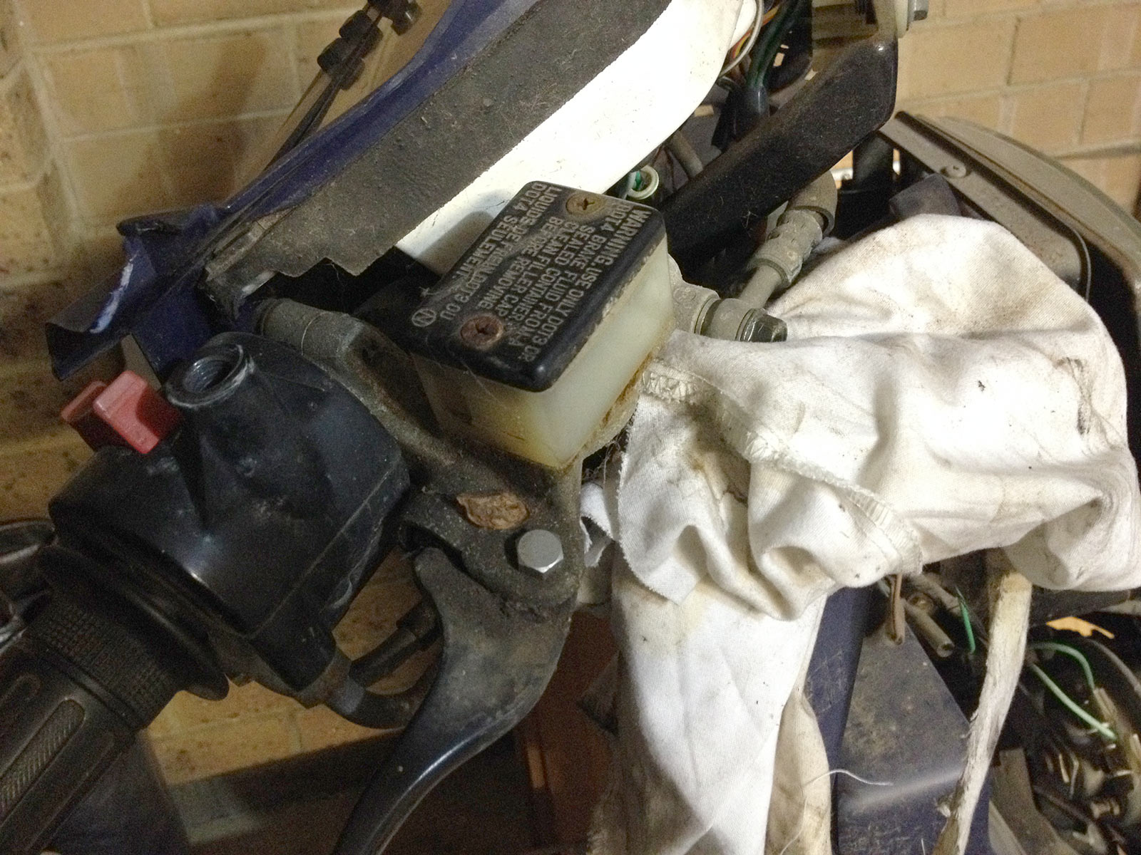
Master cylinder was mostly full of jelly but didn’t want to take any chances with brake fluid anyway :D.
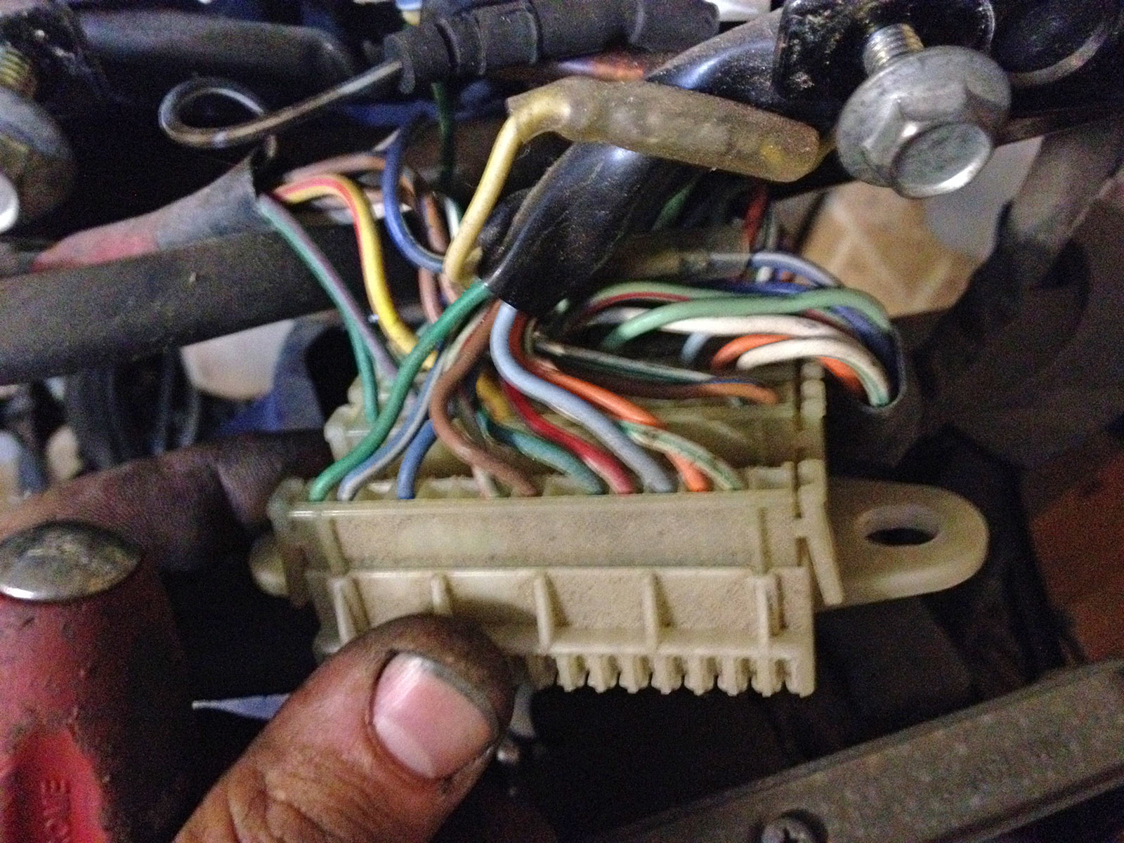
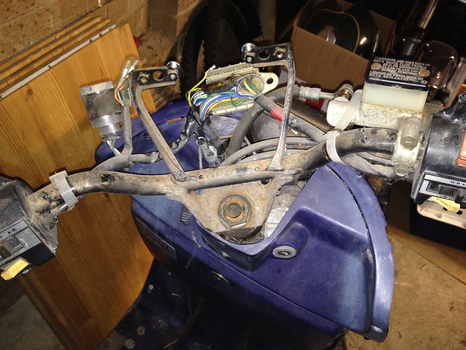
Awesome multi connector underneath the instruments. All that had to come off and apart to get the front suspension out. I was dreading plugging together a million 4-way bullet connectors but nope, Honda in the 80s did awesome stuff. This made life so much easier.
I wasn’t joking about the rust! Everything had this horrible surface rust. The top nut was stuck on good and proper, soaked it for weeks in penetrene to get it released.
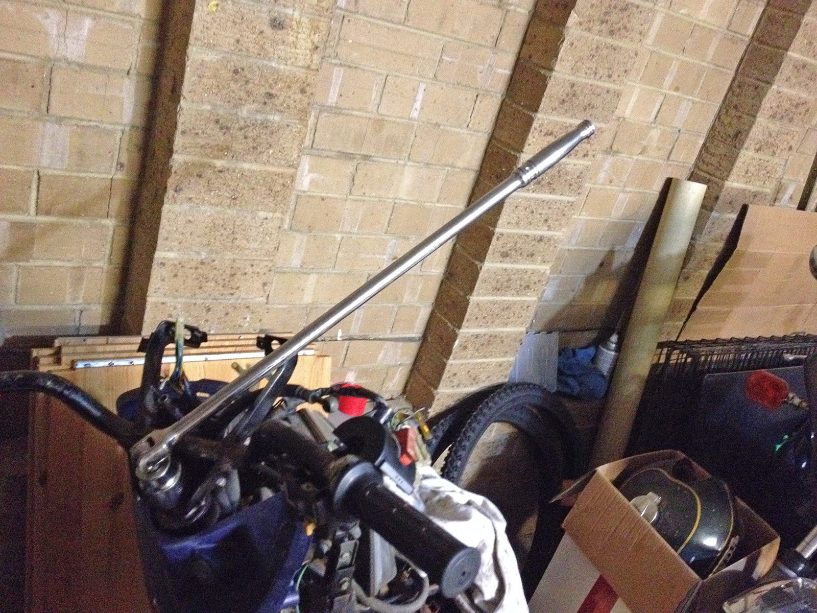
Even so, a big bar is required.
All of the suspension just needed wire wheeling, sanding, priming and painting which wasn’t too hard. One can of primer did the wheels and the suspension, one can of paint for the wheels, one for the suspension. Easy!
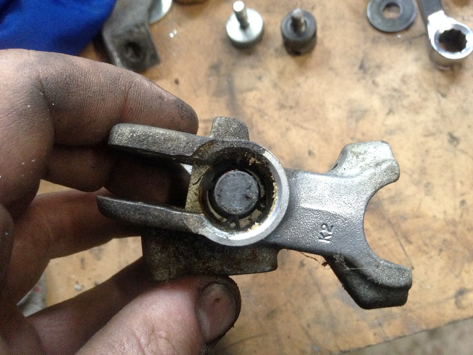
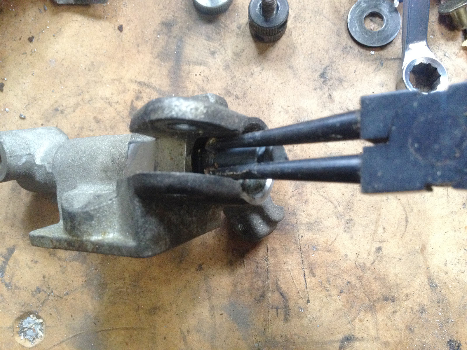
The other trickiest thing to do was putting the front ‘fork’ back in. A couple of the balls were pretty unhappy so I bought new balls (actually from a pushbike store, but that’s cause there are standard sizes). Races were good so didn’t need replacement.
Balls were #5 for the top, which are 96211-05000 and are 5/32″. There are 26 of these. #8 into the bottom, part number 96211-08000, and are 1/4″ (8/32″). 19 of the lower balls are required.
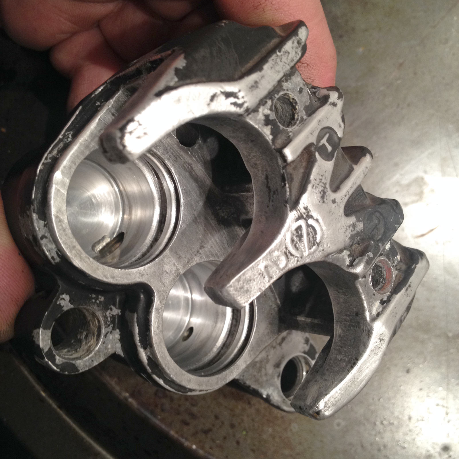
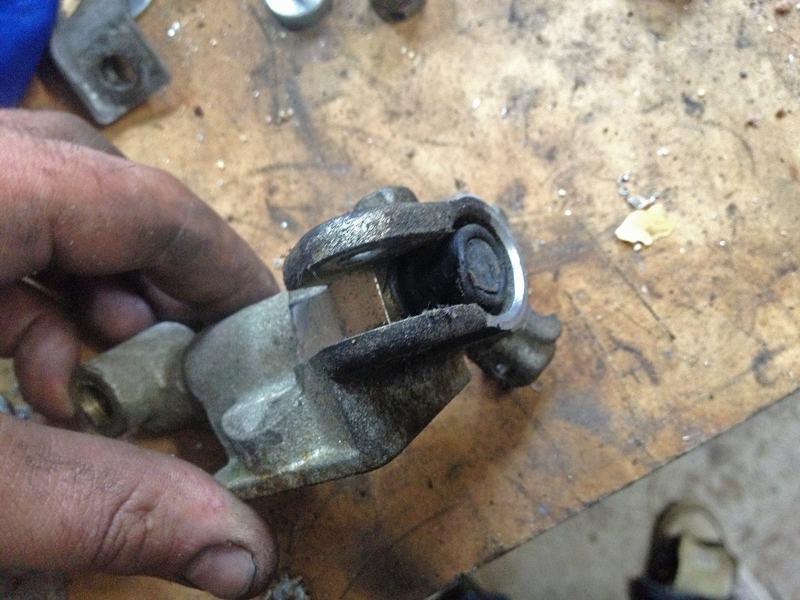
Turning to the brakes, the damned things were completely knackered. This is a problem – you can’t just grab a whole caliper arrangement cause they’re fairly unique and they’re only on a couple of years of the Euro Spacy’s and the JDM and ADM ones. There were a few on Yahoo Japan auctions but not many. Fortunately, though, rebuild kits ARE available.
… you just gotta get the caliper apart. This was problematic, the pistons were fully corroded into the bores. I tried compressed air but no dice, even after heating the caliper a lot to have the bores expand away from the pistons. In the end I drove them out using a grease gun.
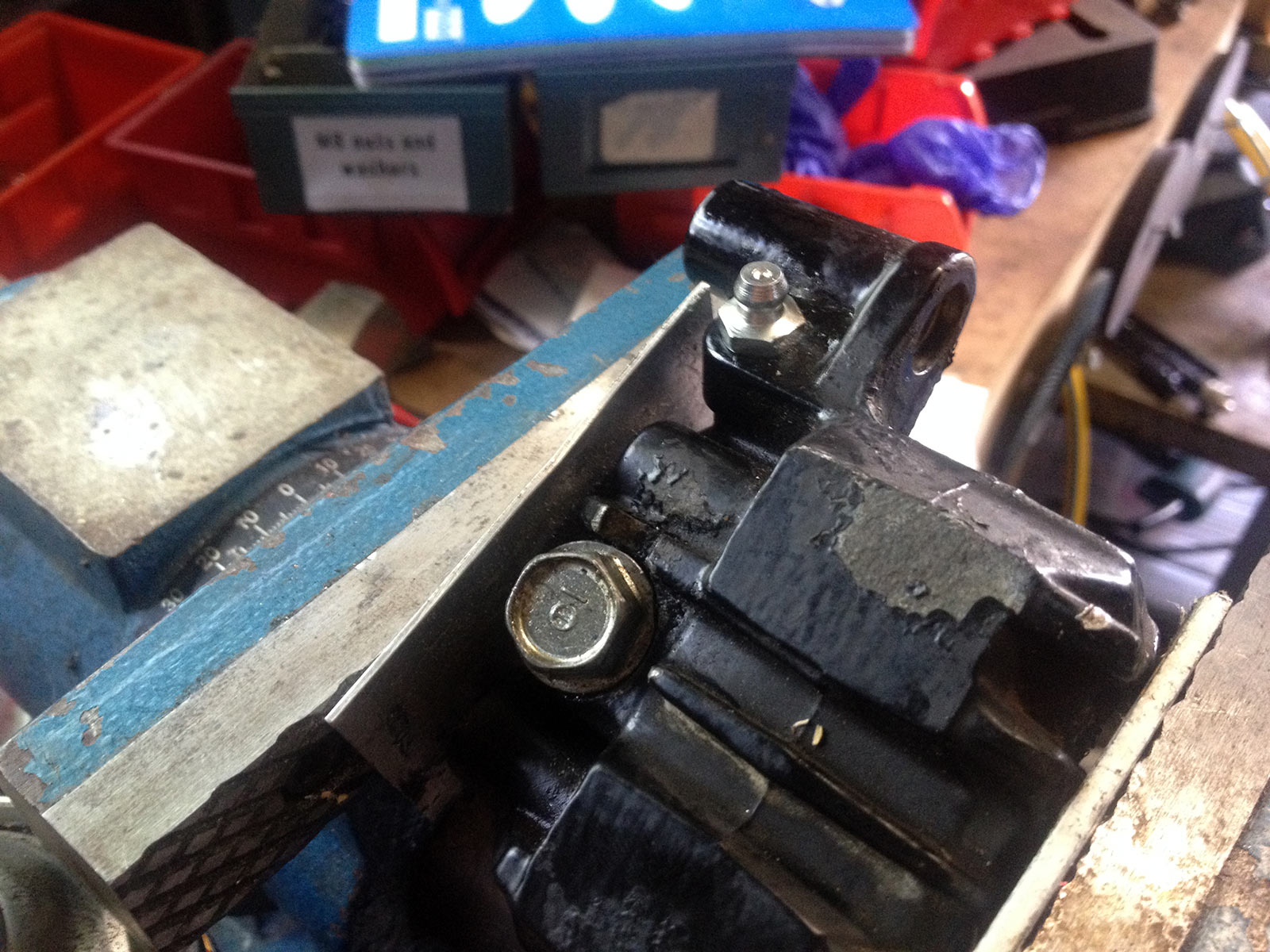
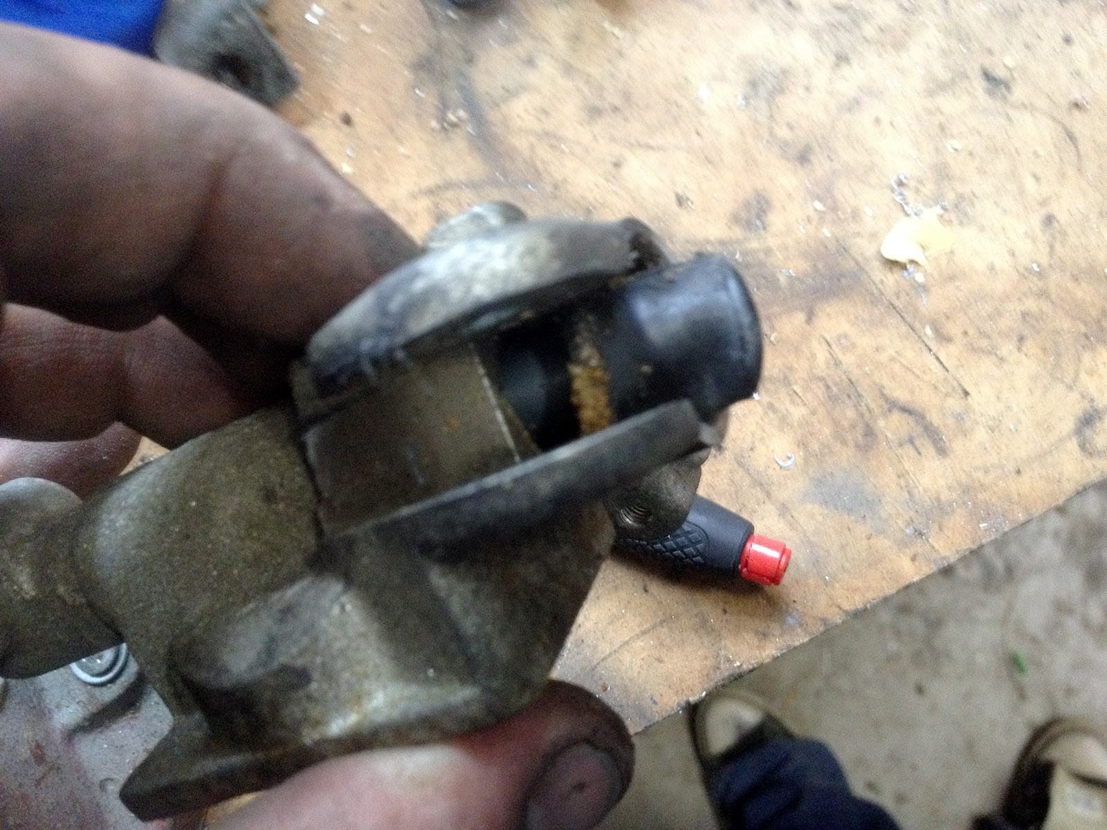
Fit grease nipple to the bleed nipple hole. Plug up the hole for the brake line.
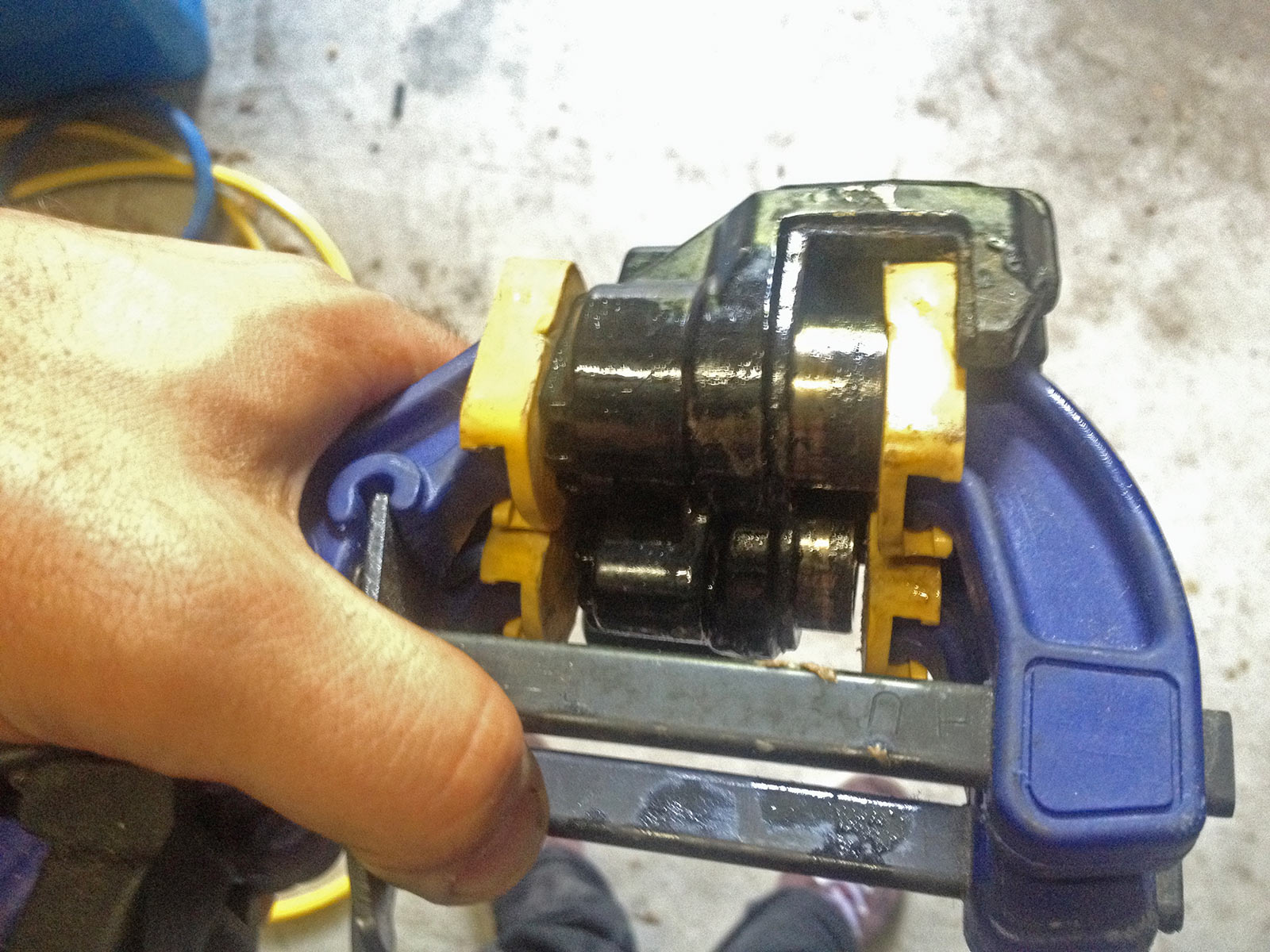
Clamps to hold the pistons so they move out basically equally.
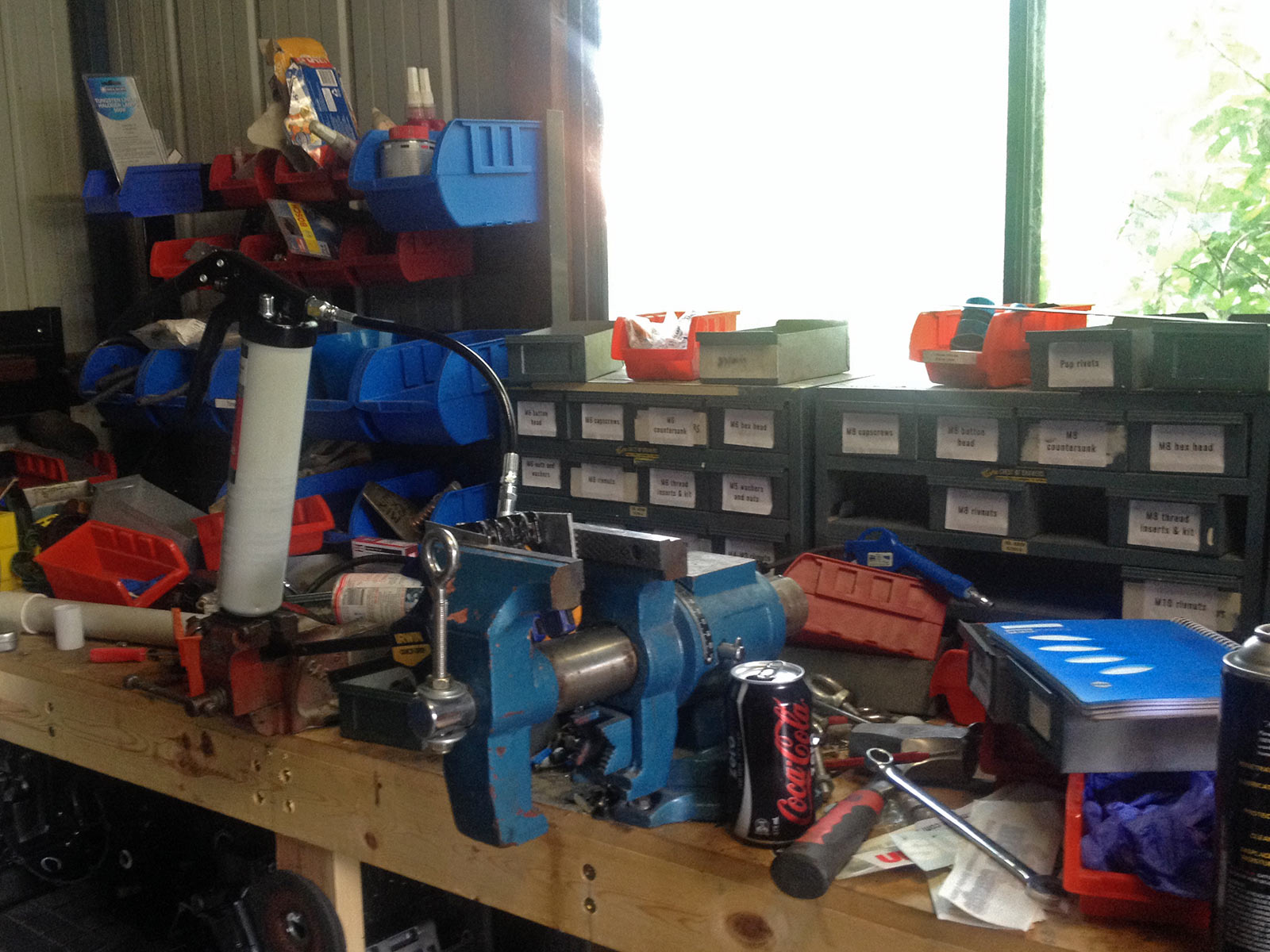
Ran out of hands but used my two different vises to hold the caliper and the grease gun. Easy then!
It worked. It took every ounce of strength of the grease gun, but the pistons popped out. Some messy cleaning up was involved, but the caliper came good.
I painted it blue, and put in new seals (from a kit from Powerhouse UK) and pistons (from Honda Aus: 45107-GE2-006). Pads are EBC SFA323/2. Ferodo apparently do one called FDB382P, and there’s a HH option in the EBC but couldn’t get my hands on it (SFA323/2HH). Later, perhaps, I’ll find some.
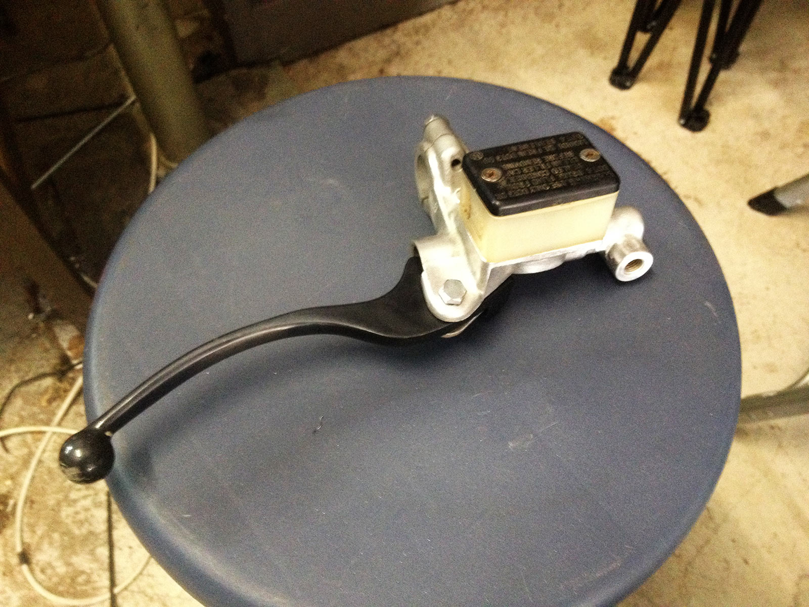
Front master cylinder also needed attention. It was super skanky and the seals were ruined.
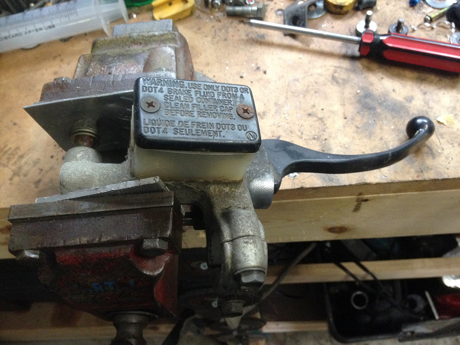
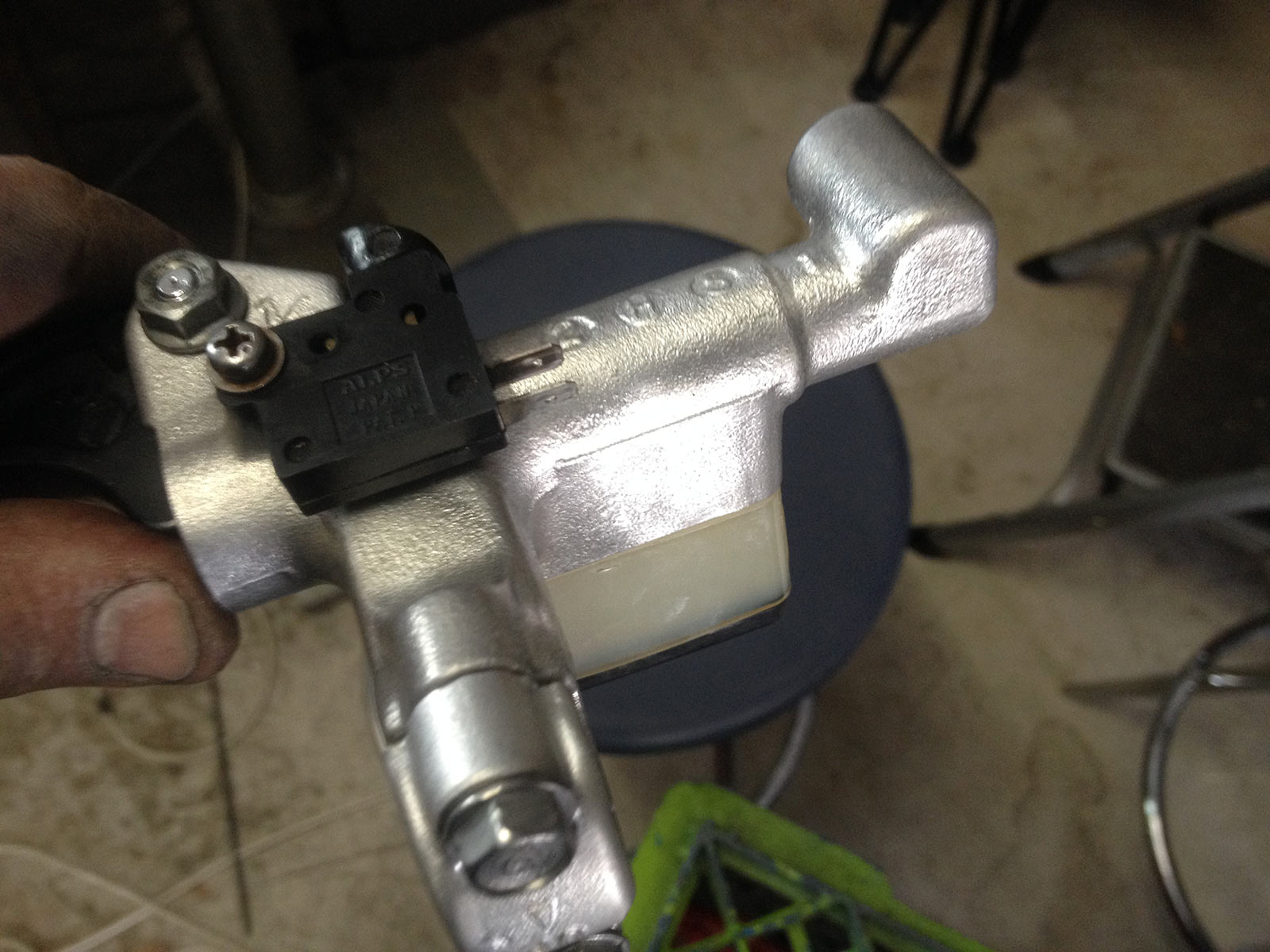
Screws for the reservoir cap were completely rusted in so that meant I had to hold it in the vise and use an impact driver. It worked!
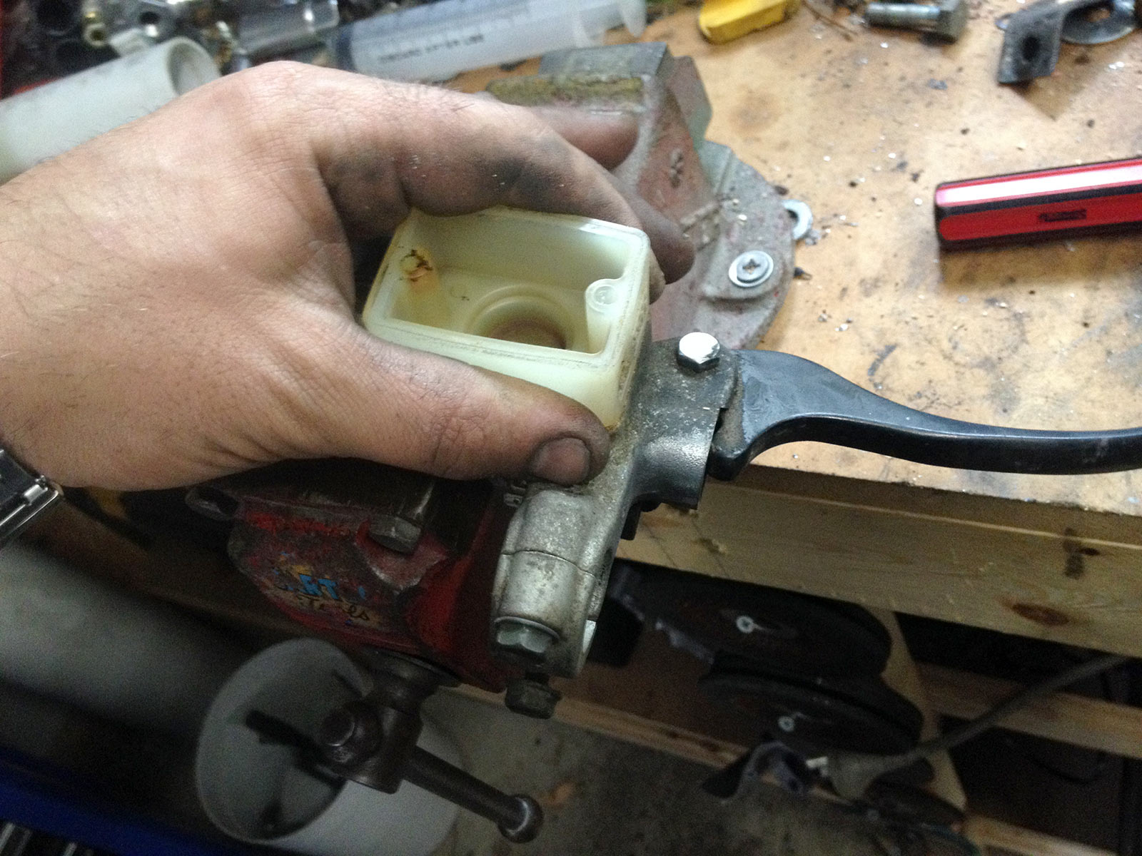
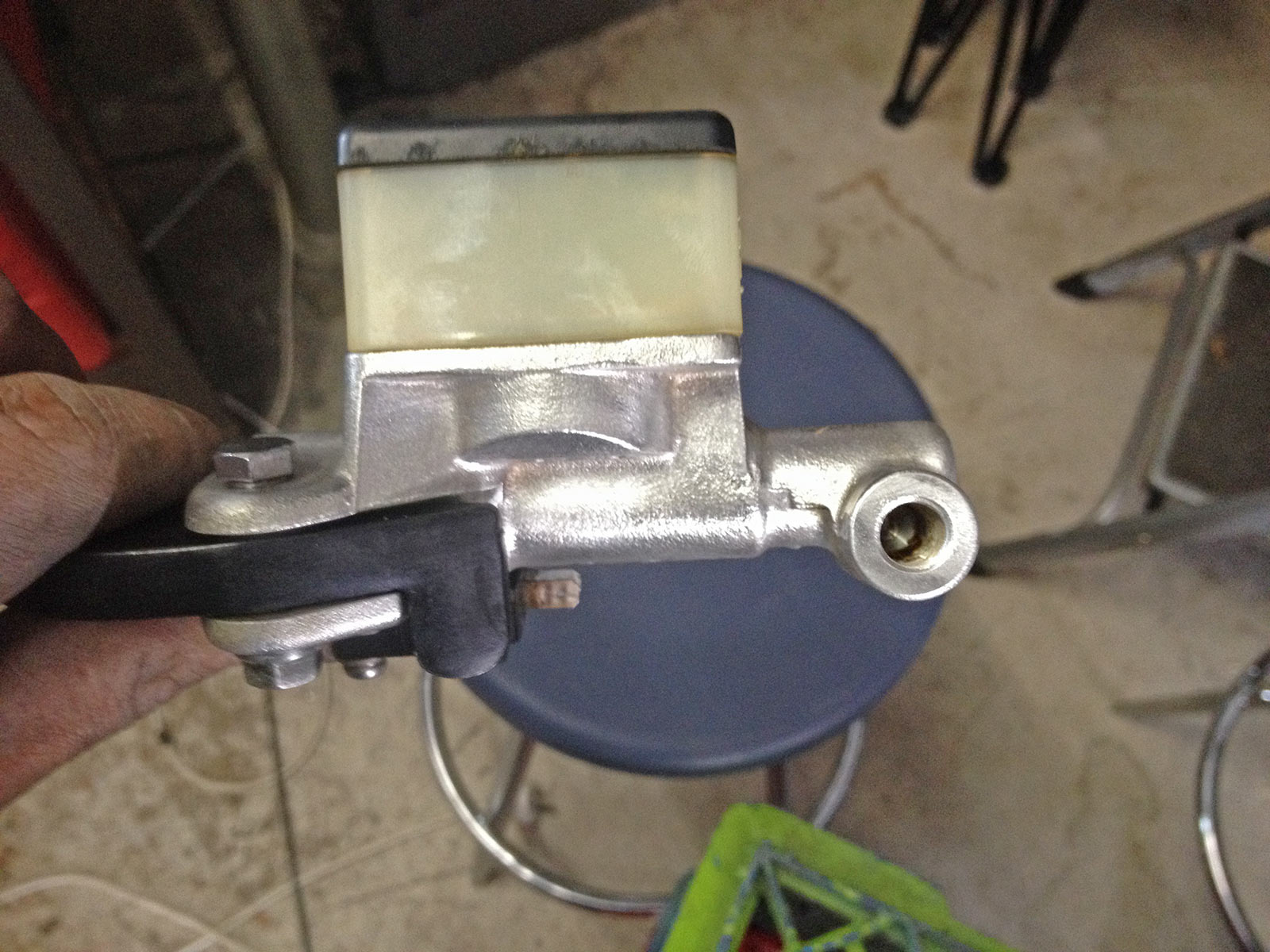
Despite my reservations, it didn’t break anything and the reservoir cap came off. The reservoir just pulls off the master cylinder at this point.
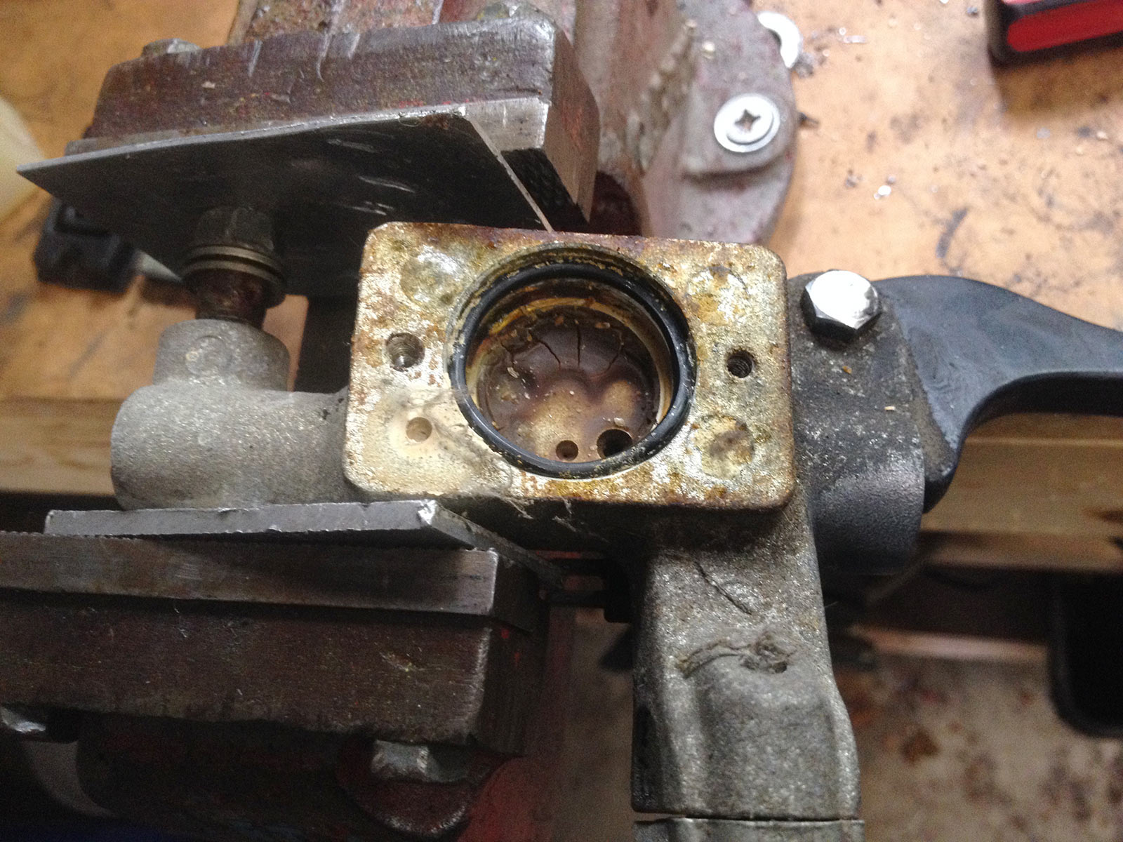
This reveals a very sad and sorry o-ring. This is available from Honda and it’s recommended you replace it: 45516-166-006.

Lever comes off.
This reveals the master cylinder piston.
Dust cap off.
Reveals the lurking circlip. This one is super tiny, had to grind a crap pair of circlip pliers to get in there.
Circlip pliers in there.
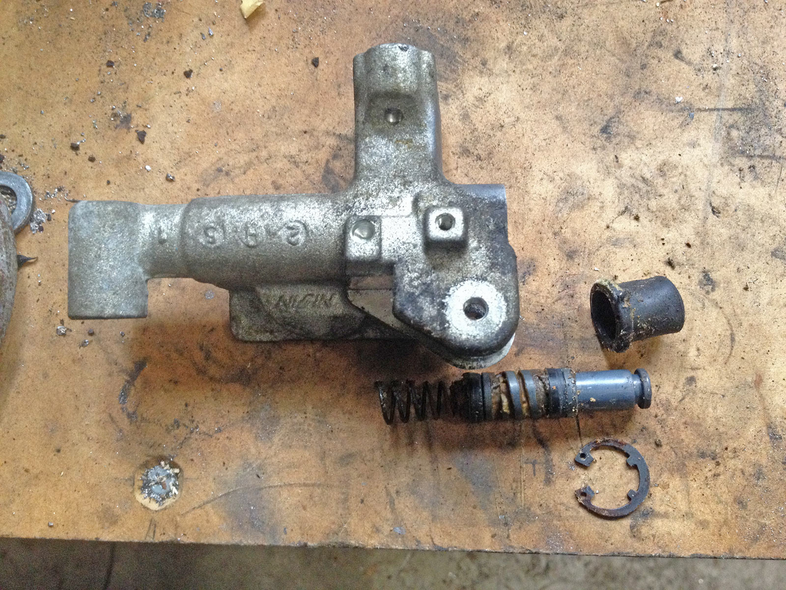
We’re apart! You can see how bad the seals are here, and the jelly from old old old brake fluid.
Lots of wire wheeling of the master cylinder occured next. A nice light bronze wheel was used and it came up a treat!
New seals came from Powerhouse UK too, although there’s apparently a Honda rebuild kit available (45530-471-831)
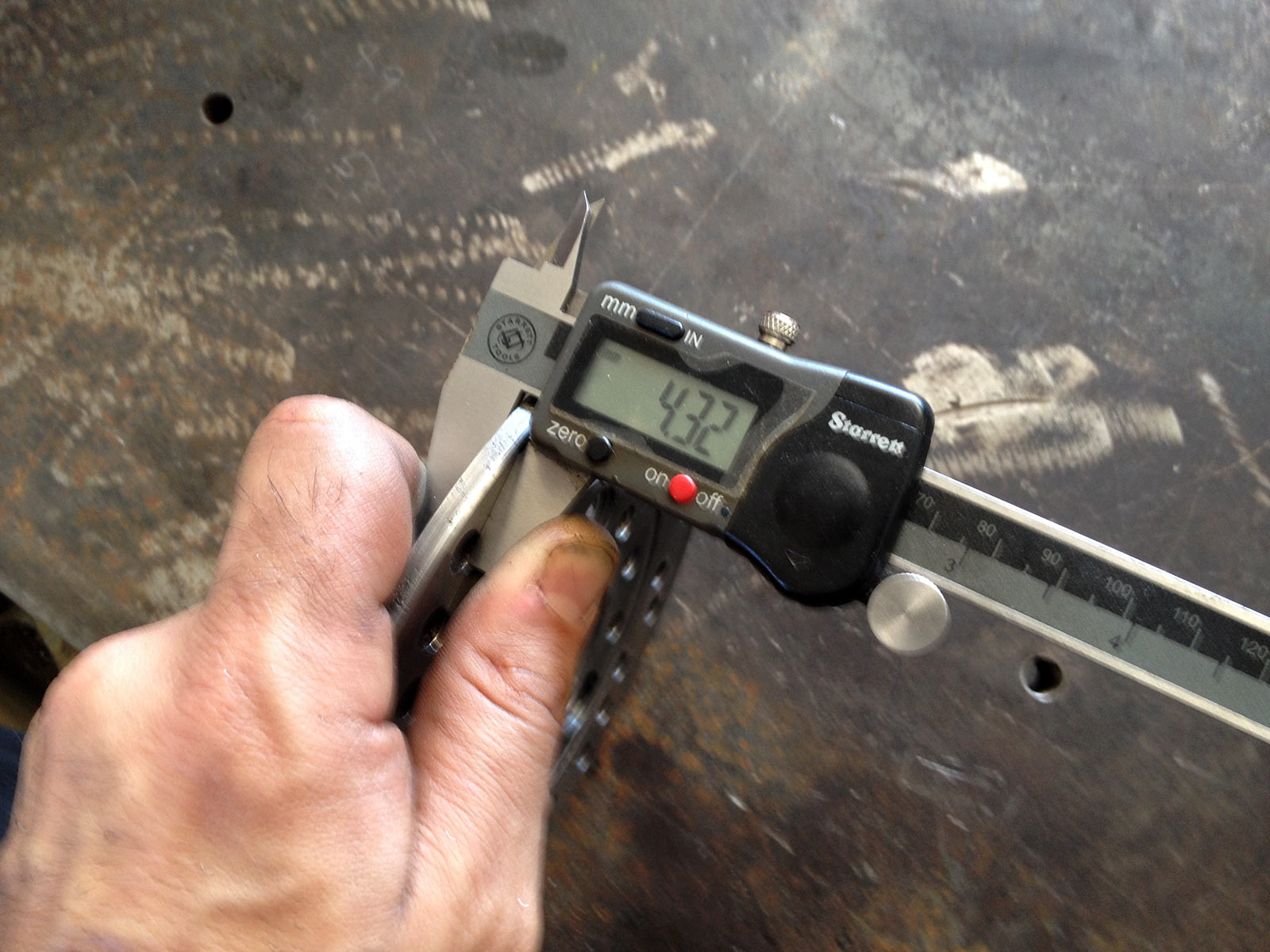
Next attention went to the disc. This was unfortunately covered in some corrosion pitting beyond normal surface rust. I’ve never machined a disc on the lathe, but hey, how hard can it be?
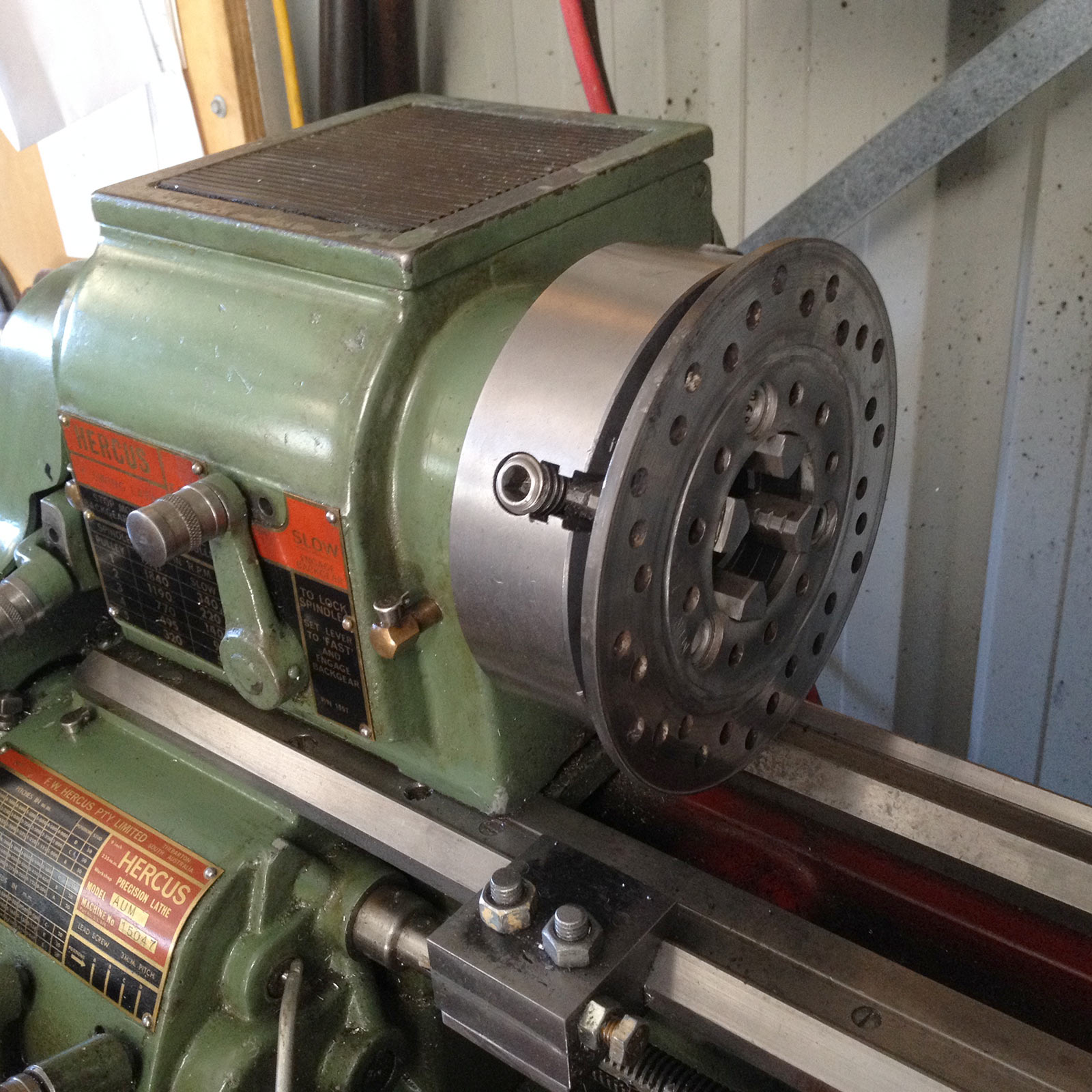
Chucked up nicely on the 4 jaw. Because I’m just facing it getting it concentric isn’t that important, though it’s good to get it close. Lucky that the 9″ lathe takes this fearsomely massive disc :).
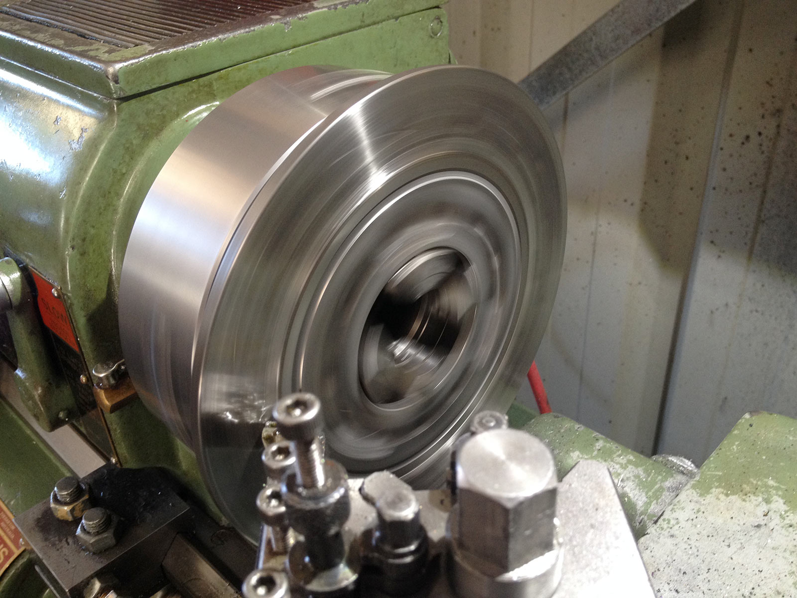
Load it up in the back gears, do a good sized cut, and use a bit of lube. Worked great.
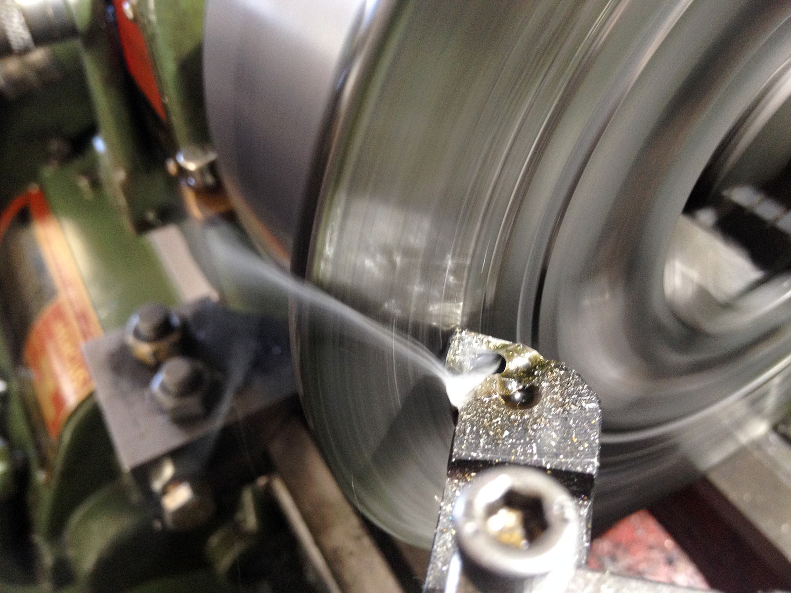
Shhhhmooooooking. Cheap carbide tooling? No worries.
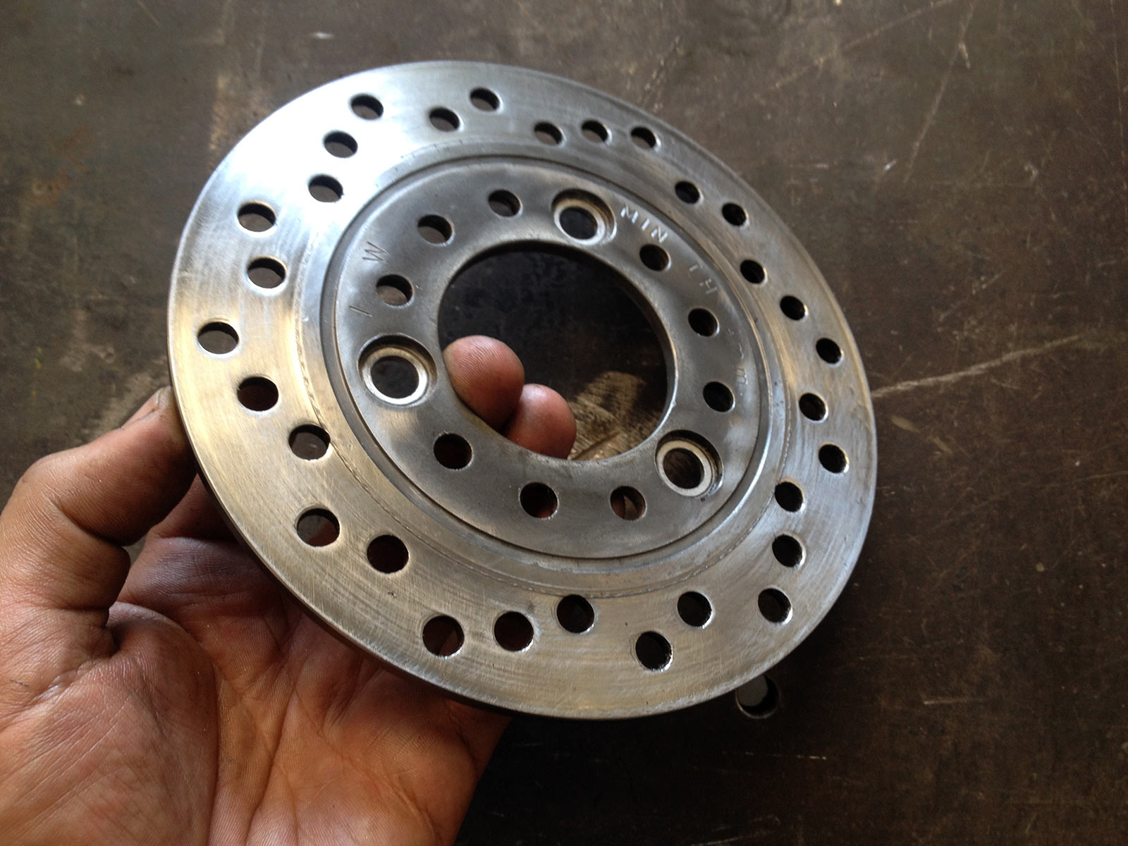
Came good. A bit of chattering at the start but it worked out ok.
She’s even legal still!
Reassembly could then begin.

After and before on the front suspension reassembly.
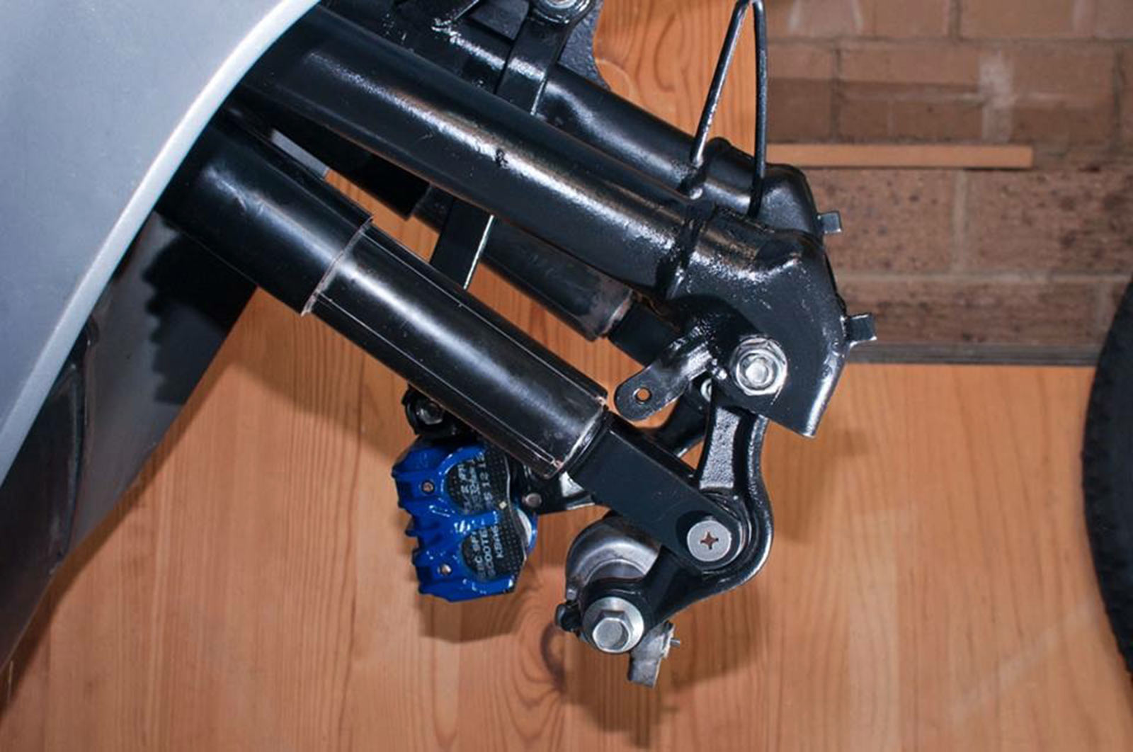
Looks great with it all painted and cleaned up. Blue caliper looks tops, too.

Lots of time on the grinder and cleaning up helped a lot. Painted so easily once it was done though.
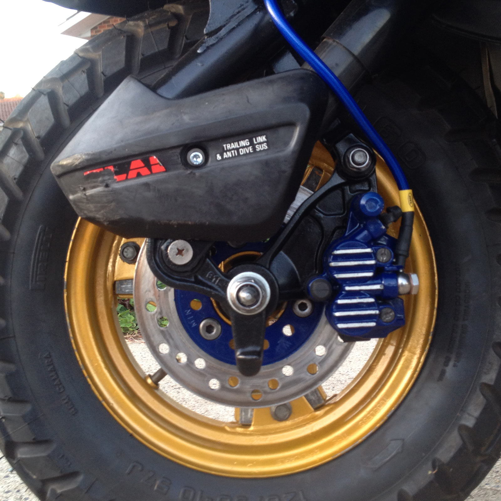
All assembled at the front. Great looking thing.
Electrical
No huge electrical gremlins to contend with, but the horn didn’t work and neither did the dashboard clock.
Dash clock wasn’t too hard, although it requires a backup battery to be installed to make it work. The battery is a ‘357’ or LR44 sized battery. To get to it you need to remove the upper plastic and the multi electrical connector. There is a little twist cap you can get to which houses this battery.
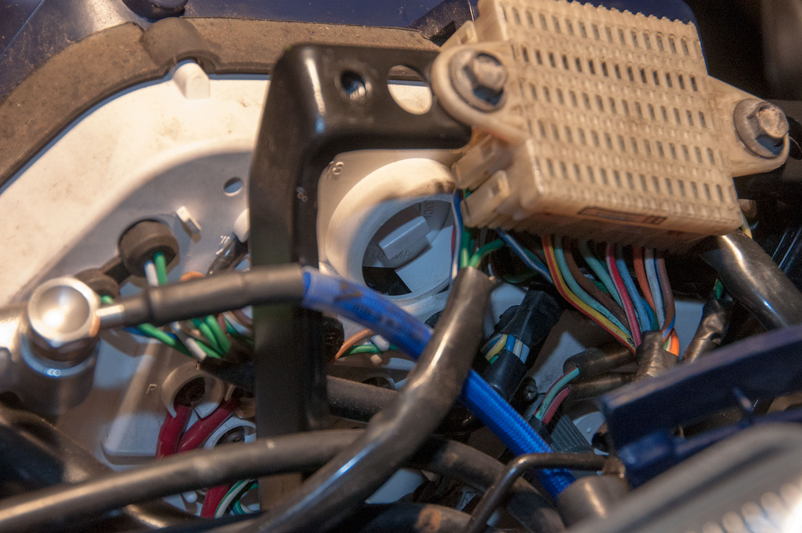
Bit hard to highlight but it’s that little cap with the flat part recessed into the dash.
The horn was simply solved by busting out the wallet and buying the cheapest twin tone snail horn setup I could find on ebay.
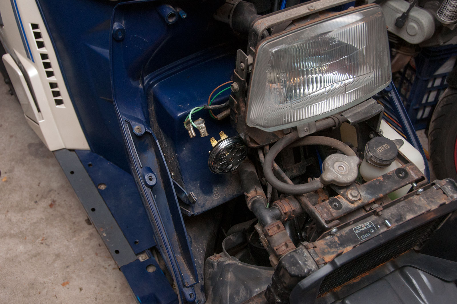
The first solution I tried was this tiny little cafe racer horn I have sitting around. It sucked – it was quiet and stupidly toned, so that had to come out. The factory horn mounts where this one is but there’s not enough room for the two tone horn setup I bought.
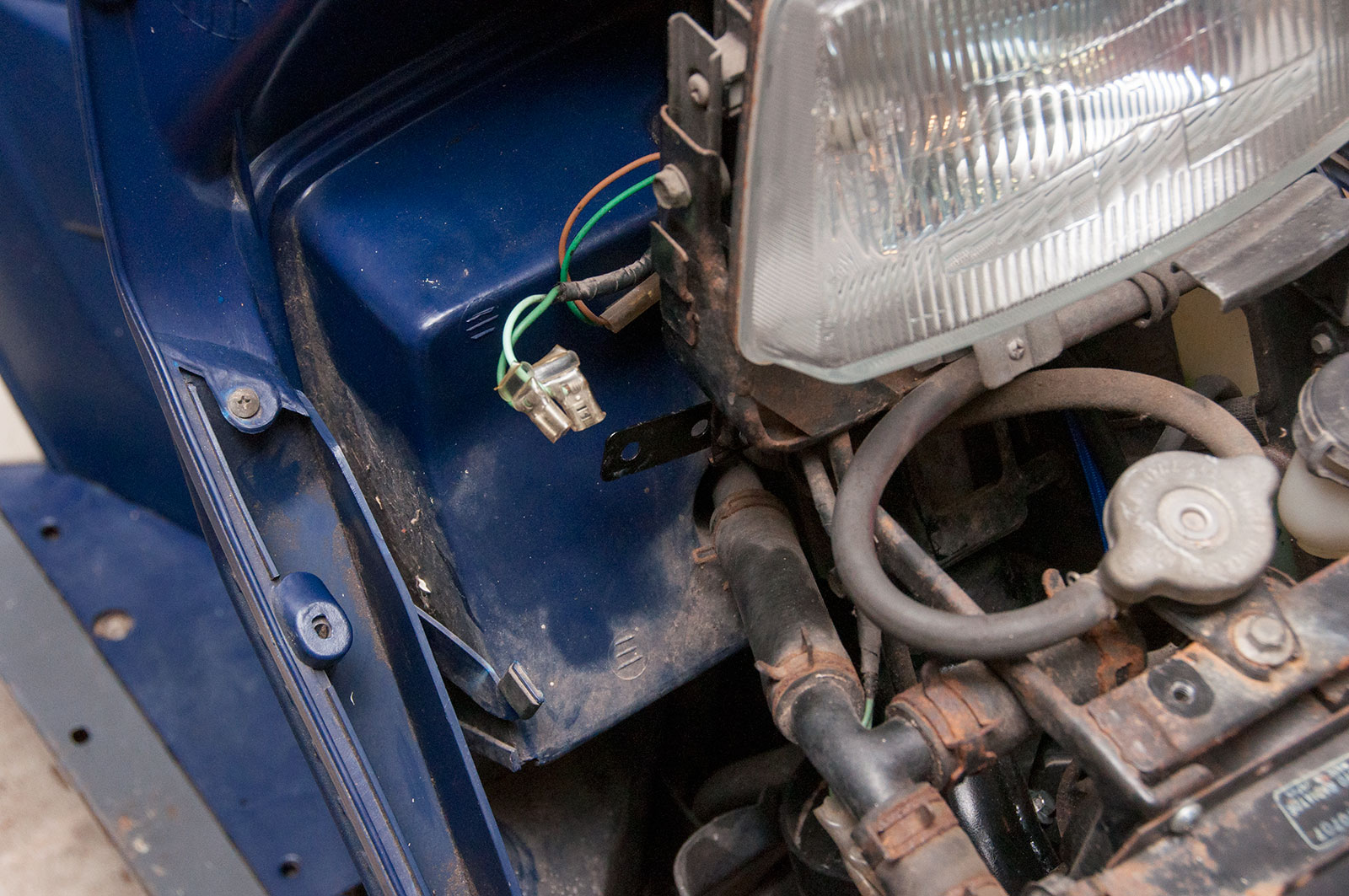
Leaving the bracket off the cafe racer horn (mounted to the factory Spacy horn location) in place, I at least have someone to mount each of the new horns.
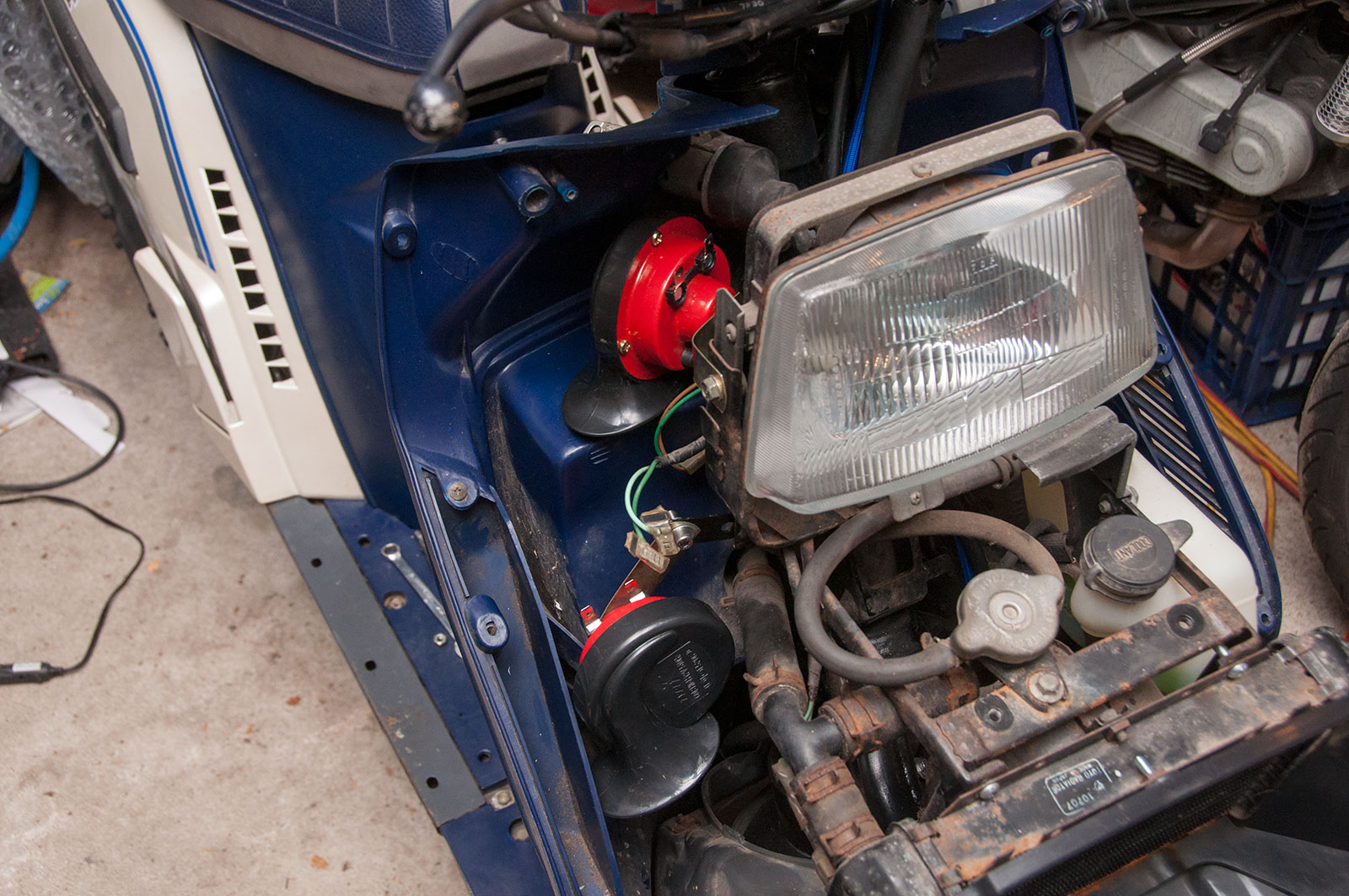
The new horns fit in pretty easily here with little brackets. The upper one is mounted off a headlight bolt, the bottom one off a horn bracket much like the factory one comes from. Perfect amount of room for the fairing still, too, there’s at least a bunch of space behind the Spacy fairing.
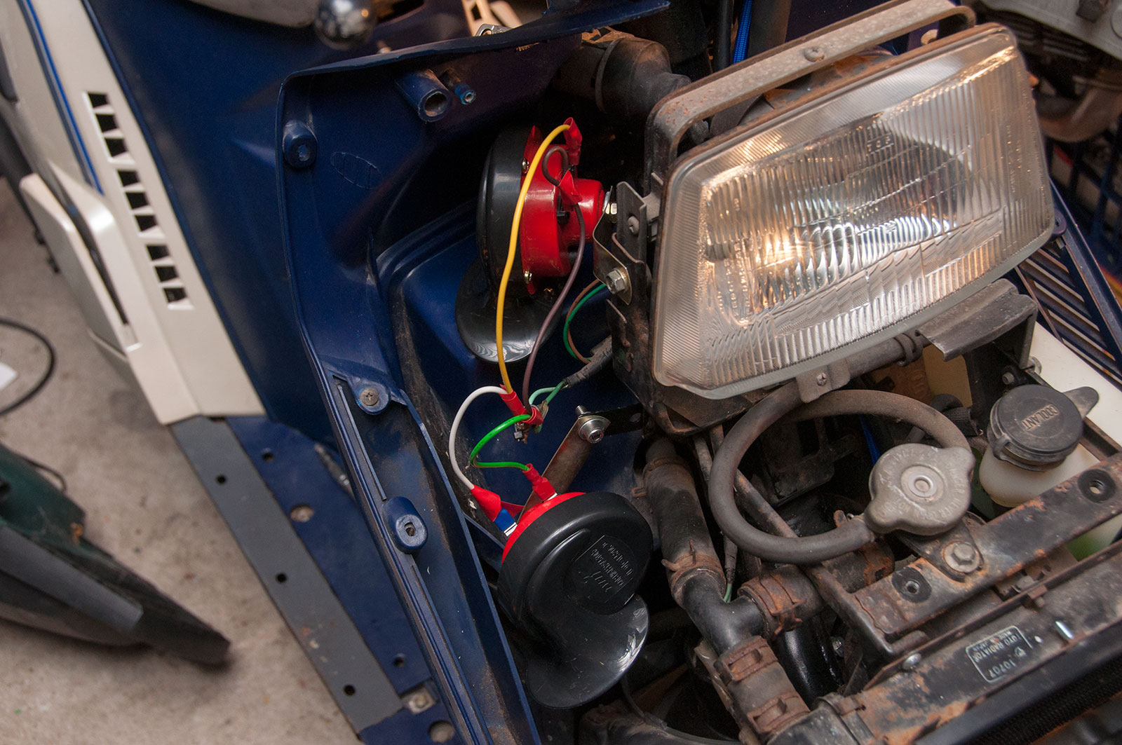
Dodgy wiring will do for registration. Need to wire each of the two horns up, so this is my solution: little Y adapters off the spade connection for the factory horn. Works well.