
JB74 wiring and wire connectors
This certainly can’t be exhaustive, as I’m not equipped to redraw or reverse-engineer the entire wiring loom. I’ll do what I can to document different things here as I find stuff and as I go.
This information wouldn’t be possible without the excellent research into connectors and wiring by Royce Murphy, an absolute legend of the Suzuki world and may he RIP. Royce provided a heap of info through Auzookers and also various FB pages over the years. I’m providing this info here free because one of the big bugbears was the way accessories companies would pump for info & then give zero credit; this way, everyone can have access to find the $2 connector they need instead of buying a $40 piggyback connector made poorly.
Sections
- Wiring
- Wiring connectors
Wiring
Leaving this blank till I work out a decent way to draw the circuits, but I’ll add info here where I need to.
4wd wiring (and vacuum circuit)
This is mostly as you get asked a lot of questions when people want to troubleshoot 4wd stuff and it’s easier to have it all on one diagram. The 4wd system is manual, also electric and additionally controlled by a vacuum circuit in the JB74.
The transfer case shifts fully mechanically to a) send power out of the front prop shaft in 4wd and b) engage the low range reduction when you shift to low range. Additionally, the transfer case engages a switch to say it is in 4wd and a further switch for when it is low range. These mode changes are communicated via the CAN bus e.g. to disable autonomous braking and traction control/ESP in low range, but also to use the ABS/ESP module to brake an individual wheel spinning on an axle more aggressively than it does in high range.
The hubs are engaged by a vacuum system. When it shifts into 4wd it uses stored vacuum from a reservoir in the front wheel arch to engage the locking hubs through one solenoid, assuming it sees sufficient vacuum. When shifting out of 4wd it uses a different vacuum solenoid to pull the engagement rings of the hubs off and disengage the front differential.
The 4wd module also receives data on the CAN bus from the transmission control module in automatic Jimnys. This includes montoring the gear data and the output speed of the transmission. This monitoring will throw an error if you try to use the low range switch to trick the car into thinking it is in low range when it is, in fact, in high range. The same monitoring does not occur in a manual Jimny as they lack sensors for the gearbox output speed and gear position.
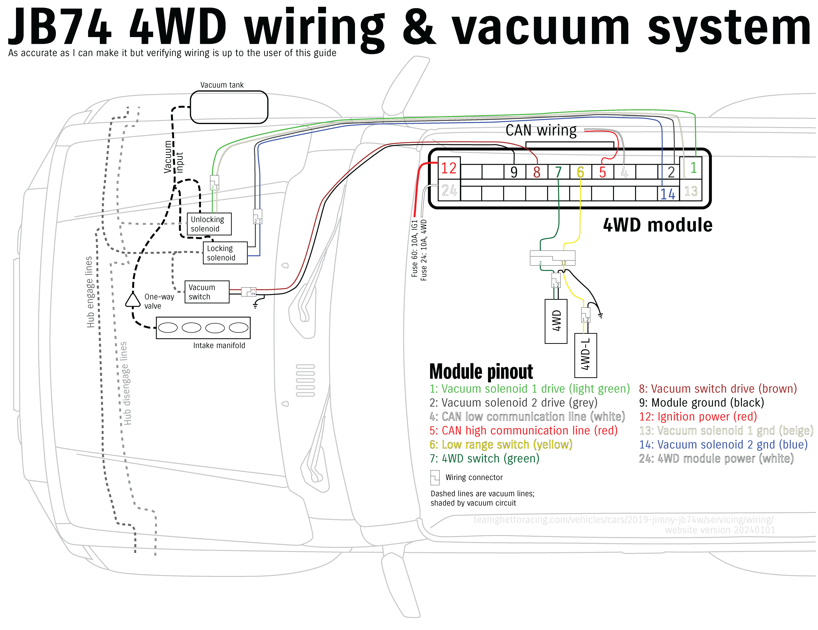
Across the CAN bus, the 4wd module looks for engine running and vehicle speed status from the ECU. It also provides A/C turnoff and transfer state back to the ECU, info on the 4wd status for the gauge cluster, and the status of the transfer case to both the ESP module and the transmission module (for automatics).
Wiring connectors
ECU
This is a big fat section so strap in. I’ve also compiled the diagnostics info from various bits and bobs to hopefully cover off on expected voltages. I will need to dig out the oscilloscope to capture some of the waveforms for complex sensors, as many do not produce a single voltage, but that can wait. To keep consistency with the factory labelling the two connectors are labelled C and E as per their wiring harnesses.
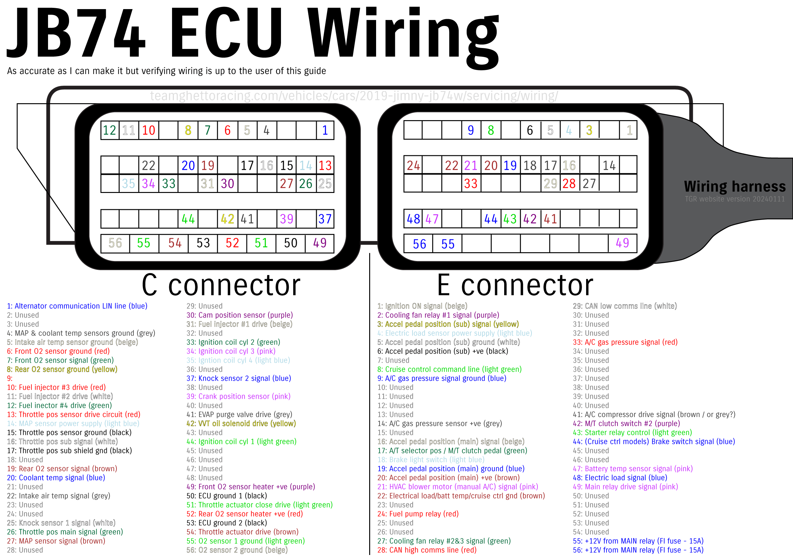
C connector pinout, wiring and diagnostics
| Pin | Wire colour | Circuit | Diagnostics |
|---|---|---|---|
| C-01 | Blue | Alternator communication LIN line | Complex waveform |
| C-04 | Grey | MAP & coolant temp sensors ground | < 0.3V, ignition on |
| C-05 | Beige | Intake air temp sensor ground | < 0.3V, ignition on |
| C-06 | Red | Front O2 sensor ground | < 0.3V, ignition on |
| C-07 | Green | Front O2 sensor signal | Complex waveform |
| C-08 | Yellow | Rear O2 sensor ground | < 0.3V, ignition on |
| C-10 | Red | Cyl 3 injector | 10-14V, ignition on; complex waveform when running |
| C-11 | White | Cyl 2 injector | 10-14V, ignition on; complex waveform when running |
| C-12 | Green | Cyl 4 injector | 10-14V, ignition on; complex waveform when running |
| C-13 | Red | Throttle position sensor drive | 4.5-5.5V, ignition on |
| C-14 | Light blue | MAP sensor drive | 4.5-5.5V, ignition on |
| C-15 | Black | Throttle position sensor ground | < 0.3V, ignition on |
| C-16 | White | Throttle position sensor (sub) signal | 4.0-4.2V, ignition on & throttle pedal released 0.5-0.7V, ignition on & throttle pedal fully depressed |
| C-17 | Black | Throttle position sensor (sub) shield ground | < 0.3V, ignition on |
| C-19 | Brown | Rear O2 sensor signal | Complex waveform |
| C-20 | Blue | Coolant temp signal | Ignition on will give voltages at coolant temps as follows: * 0.2-0.5V @ 100ºC * 1.0-1.4V @ 50ºC * 3.2-3.6V @ 0ºC |
| C-22 | Grey | Intake air temp signal | Ignition on will give voltages at air temps as follows: * 0.4-0.8V @ 80ºC * 1.3-1.7V @ 40ºC * 3.2-3.6V @ 0ºC |
| C-25 | White | Knock sensor 1 signal | Engine at idle will give 1-2V Complex waveform signal |
| C-26 | Green | Throttle position sensor (main) signal | 0.8-1.0V, ignition ON & throttle pedal released 4.3-4.5V, ignition ON & throttle pedal fully depressed |
| C-27 | Brown | MAP sensor signal | Ignition on 4.0-4.2V Engine at idle when warm, 100 kPa air pressure: 1.5-1.8V Complex waveform signal |
| C-30 | Purple | Cam position sensor | Ignition on either 0V or 4-5V Complex waveform signal |
| C-31 | Beige | Cyl 1 injector | 10-14V, ignition on; complex waveform when running |
| C-33 | Green | Cyl 2 coil | Ignition on: 0V Complex waveform signal |
| C-34 | Pink | Cyl 3 coil | Ignition on: 0V Complex waveform signal |
| C-35 | Light blue | Cyl 4 coil | Ignition on: 0V Complex waveform signal |
| C-37 | Blue | Knock sensor 2 signal | Engine at idle will give 1-2V Complex waveform signal |
| C-39 | Pink | Crank position sensor | Ignition on either 0V or 4-5V Complex waveform signal |
| C-41 | Grey | Evap canister purge valve | 10-14V, ignition on; complex waveform when running |
| C-42 | Yellow | VVT control oil solenoid | 10-14V, ignition on; complex waveform when running |
| C-44 | Light green | Cyl 1 coil | Ignition on: 0V Complex waveform signal |
| C-49 | Purple | Front O2 sensor heater | Complex waveform |
| C-50 | Black | ECU ground #1 | < 0.3V, ignition on |
| C-51 | Light green | Throttle actuator close drive circuit | Complex waveform signal |
| C-52 | Red | Rear O2 sensor heater | Complex waveform |
| C-53 | Black | ECU ground #2 | < 0.3V, ignition on |
| C-54 | Brown | Throttle actuator open drive circuit | Complex waveform signal |
| C-55 | Light green | Front O2 sensor shield ground | < 0.3V, ignition on |
| C-56 | Beige | Rear O2 sensor shield ground | < 0.3V, ignition on |
E connector pinout, wiring and diagnostics
| Pin | Wire colour | Circuit | Diagnostics |
|---|---|---|---|
| E-01 | Beige | Igniton on signal | Ignition OFF or ACC: 0-0.3V Ignition ON: 10-14V |
| E-02 | Purple | Radiator fan relay #1 | 0-0.3V: A/C switch off, ignition ON, coolant temp > 97ºC 10-14V: A/C switch off, ignition ON, coolant temp < 95ºC |
| E-03 | Yellow | Accelerator pedal (sub) signal | 0.325-0.425V, ignition ON & throttle pedal released 2.15-2.25V, ignition ON & throttle pedal fully depressed |
| E-04 | Light blue | Electric load sensor power | 4.5-5.5V ignition ON |
| E-05 | White | Accelerator pedal (sub) ground | < 0.3V, ignition on |
| E-06 | Black | Accelerator pedal (sub) power | 4.5-5.5V ignition ON |
| E-08 | Light green | Cruise control commands | 0-0.2V Cruise switch ON 0.3-0.6V Cancel switch ON 0.88V Limit switch ON 1.2-1.6V SET – switch ON 2.0-2.4V RES + switch ON 3.5-4.3V Ignition ON no other switches pressed |
| E-09 | Blue | A/C refrigerant pressure sensor ground | < 0.3V, ignition on |
| E-14 | Grey | A/C refrigerant pressure sensor power | 4.5-5.5V ignition ON |
| E-16 | Beige | Accelerator pedal (main) signal | 0.7-0.8V, ignition ON & throttle pedal released 4.35-4.45V, ignition ON & throttle pedal fully depressed |
| E-17 | Green | (A/T) Transmission range sensor (M/T) Clutch pedal switch #1 | 0V: (A/T) ignition ON, transmission P or N (M/T) ignition ON, clutch pedal depressed 10-14V: (A/T) ignition ON, transmission not in P or N (M/T) ignition ON, clutch pedal released |
| E-18 | Light blue | Brake light switch signal | 0V: ignition ON, brake pedal released 10-14V: ignition ON, brake pedal pressed |
| E-19 | Blue | Accelerator pedal (main) ground | < 0.3V, ignition on |
| E-20 | Brown | Accelerator pedal (main) power | 4.5-5.5V ignition ON |
| E-21 | Pink | Blower motor (manual A/C models) signal | Ignition ON gives the following: 10-14V: blower switch off 5-7V: blower switch 1st position 0-0.3V: blower switch 2nd or higher position |
| E-22 | Brown | Grounds for: * Electric load sensor * Battery temperature sensor * Cruise control switch | < 0.3V, ignition on |
| E-24 | Red | Fuel pump relay | Complex waveform |
| E-27 | Green | Radiator fan relay #2 and 3 | 0-0.3V: A/C switch off, ignition ON, coolant temp > 102ºC 10-14V: A/C switch off, ignition ON, coolant temp < 100ºC |
| E-28 | Red | CAN high communication line | Complex waveform |
| E-29 | White | CAN low communication line | Complex waveform |
| E-33 | Red | A/C refrigerant pressure sensor signal | 0.9-1.3V Engine running, A/C compressor off 1.6-2.6V Engine running, A/C compressor on |
| E-41 | Grey | A/C compressor clutch relay | 0-0.3V Engine running, A/C compressor on 10-14V Engine running, A/C compressor off |
| E-42 | Purple | (M/T) Clutch pedal switch #2 | 0-0.3V: ignition ON, clutch pedal depressed 10-14V: ignition ON, clutch pedal released |
| E-43 | Light green | Starter motor control relay | Ignition ON: 0-0.3V Ignition START: 6-12V |
| E-44 | Blue | Brake switch signal (cruise control models only) | 0-0.3V: ignition ON, brake pedal pressed 10-14V: ignition ON, brake pedal released |
| E-48 | Blue | Electric load sensor signal | 3.1V: Ignition ON, headlights ON high beam, blower speed MAX 3.4V: Ignition ON, minimal other loads |
| E-49 | Pink | Main relay driver | 0-0.3V: Ignition ON 10-14V: 10 seconds after ignition: OFF |
| E-55 | Blue | Permanent power | Fed from FI (fuse 28) 15A via main relay |
| E-56 | Blue | Permanent power | Fed from FI (fuse 28) 15A via main relay |
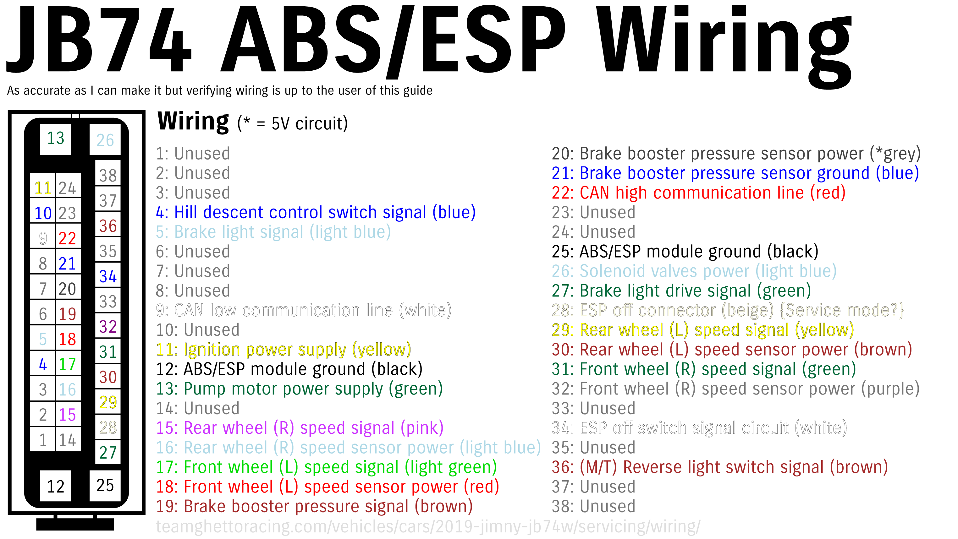
ABS-ESP module
Another biggish one, but not quite as big as the ECU. One circuit (the brake master cylinder pressure) appears to be 5V.
| Pin | Wire colour | Circuit |
|---|---|---|
| 4 | Blue | Hill descent control switch |
| 5 | Light blue | Brake light signal |
| 9 | White | CAN low communication line |
| 11 | Yellow | Ignition power supply |
| 12 | Black | ABS/ESP module ground |
| 13 | Green | Pump motor power supply |
| 15 | Pink | Wheel speed sensor signal (rear right) |
| 16 | Light blue | Wheel speed sensor power (rear right) |
| 17 | Light green | Wheel speed sensor signal (front left) |
| 18 | Red | Wheel speed sensor power (front left) |
| 19 | Brown | Brake booster pressure signal |
| 20 | Grey | Brake booster pressure sensor power |
| 21 | Blue | Brake booster pressure sensor ground |
| 22 | Red | CAN high communication line |
| 25 | Black | ABS/ESP module ground |
| 26 | Light blue | Solenoid valves power |
| 27 | Green | Brake light signal |
| 28 | Beige | Service mode connector |
| 29 | Yellow | Wheel speed sensor signal (rear left) |
| 30 | Brown | Wheel speed sensor power (rear left) |
| 31 | Green | Wheel speed sensor signal (front right) |
| 32 | Purple | Wheel speed sensor power (front right) |
| 34 | White | ESP off switch |
| 36 | Brown | (M/T) reverse light switch |
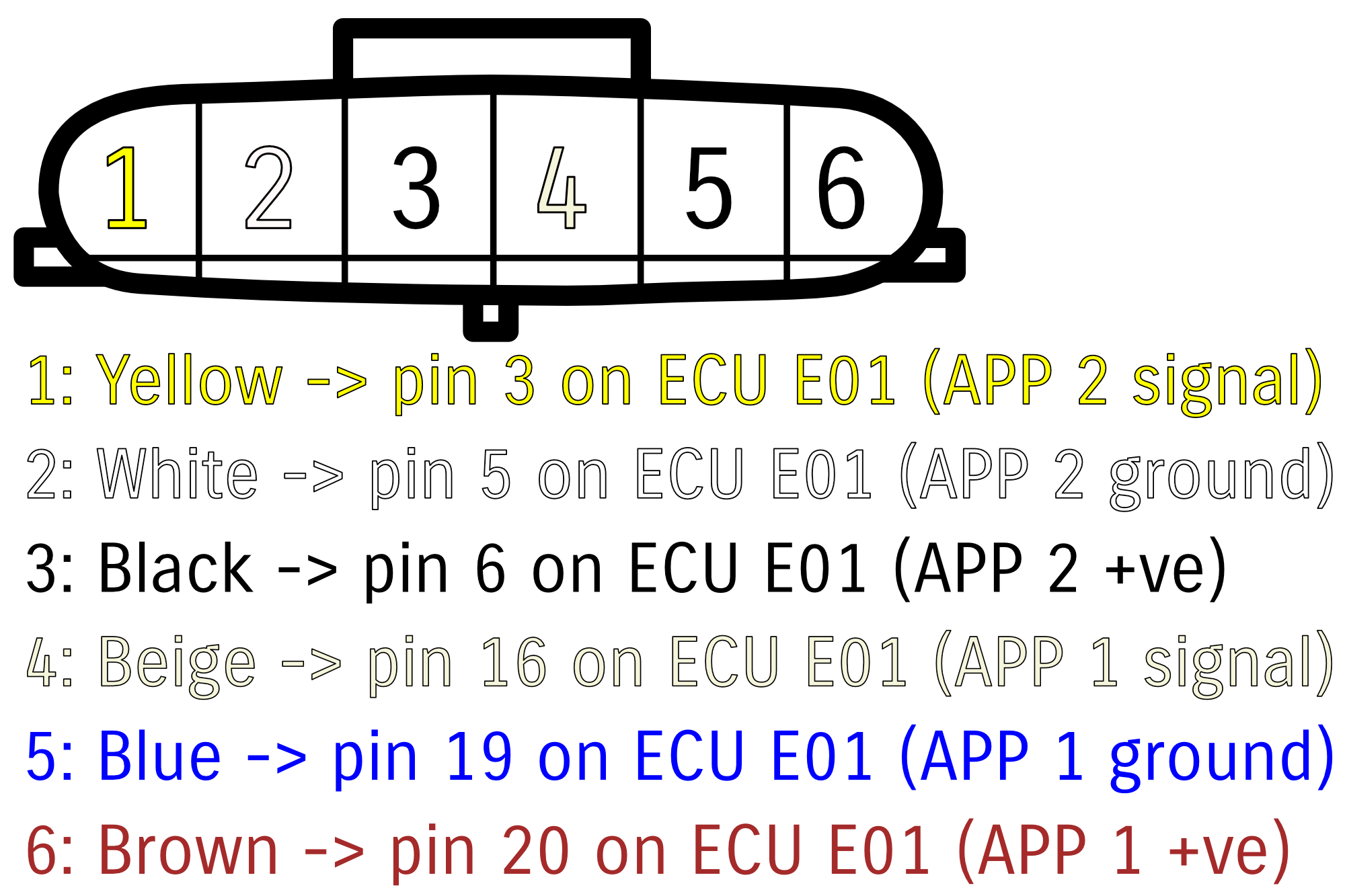
Accelerator pedal
| Pin | Wire colour | Circuit |
|---|---|---|
| 1 | Yellow | Signal, accelerator pedal sub circuit |
| 2 | White | Ground, accelerator pedal sub circuit |
| 3 | Black | Positive 5V feed, accelerator pedal sub circuit |
| 4 | Beige | Signal, accelerator pedal main circuit |
| 5 | Blue | Ground, accelerator pedal main circuit |
| 6 | Brown | Positive 5V feed, accelerator pedal main circuit |
Accelerator pedal sensor parameters
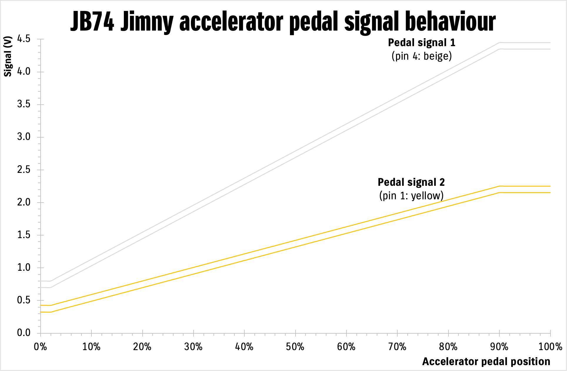
| APP 1 / Main signal | APP 2 / sub signal | Accelerator position |
|---|---|---|
| 0.7 – 0.8 V | 0.325 – 0.425 V | 0 – 2% travel |
| 4.35 – 4.45 V | 2.15 – 2.25 V | 90 – 100% travel |
Related to the throttle pedal is the ESP maintenance mode connector. I believe the connector on the harness is Yazaki/Sumitomo 7283-1020, with the mating connector you’d need to make up a nice plug being 7282-1020. This would also be specified as 090IIU-2P-2 as a connector.
Headlights (LED)
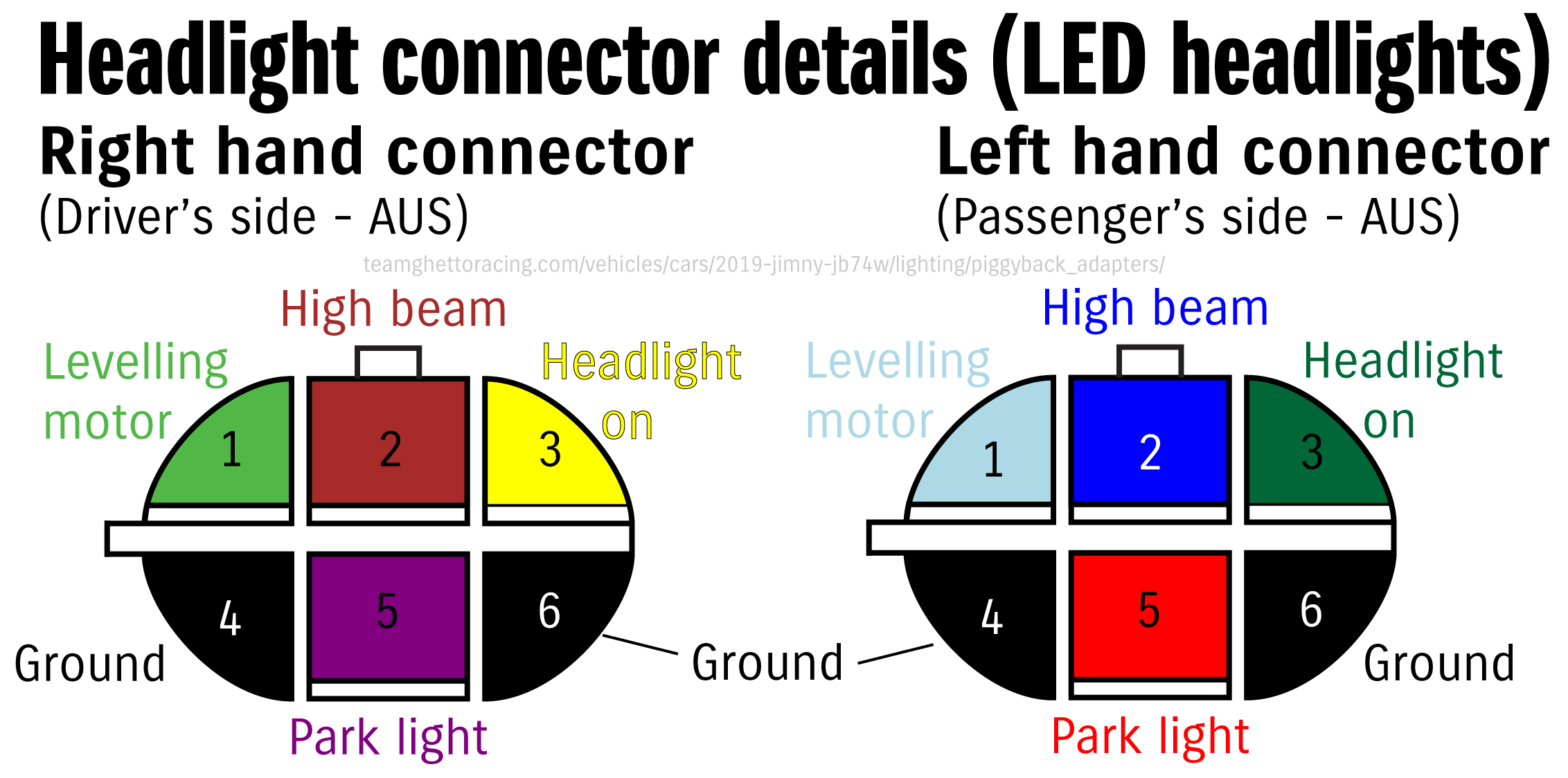
These use a 6 pin Sumitomo TS series connector. If making up a piggyback harness you need both the male and female connectors: 6188-0175 and 6189-0323. If just remaking the headlight connector on the car side of the wiring loom then 6189-0323 suffices.
| Pin number | Wire colour | Item |
|---|---|---|
| 1 | Light blue (L); light green (R) | Headlight levelling motor |
| 2 | Blue (L); brown (R) | High beam |
| 3 | Green (L); yellow (R) | Headlight on signal |
| 4 | Black | Ground (headlight) |
| 5 | Red (L); purple (R) | Park light |
| 6 | Black | Ground (high beam) |
Airbag module (SDM)
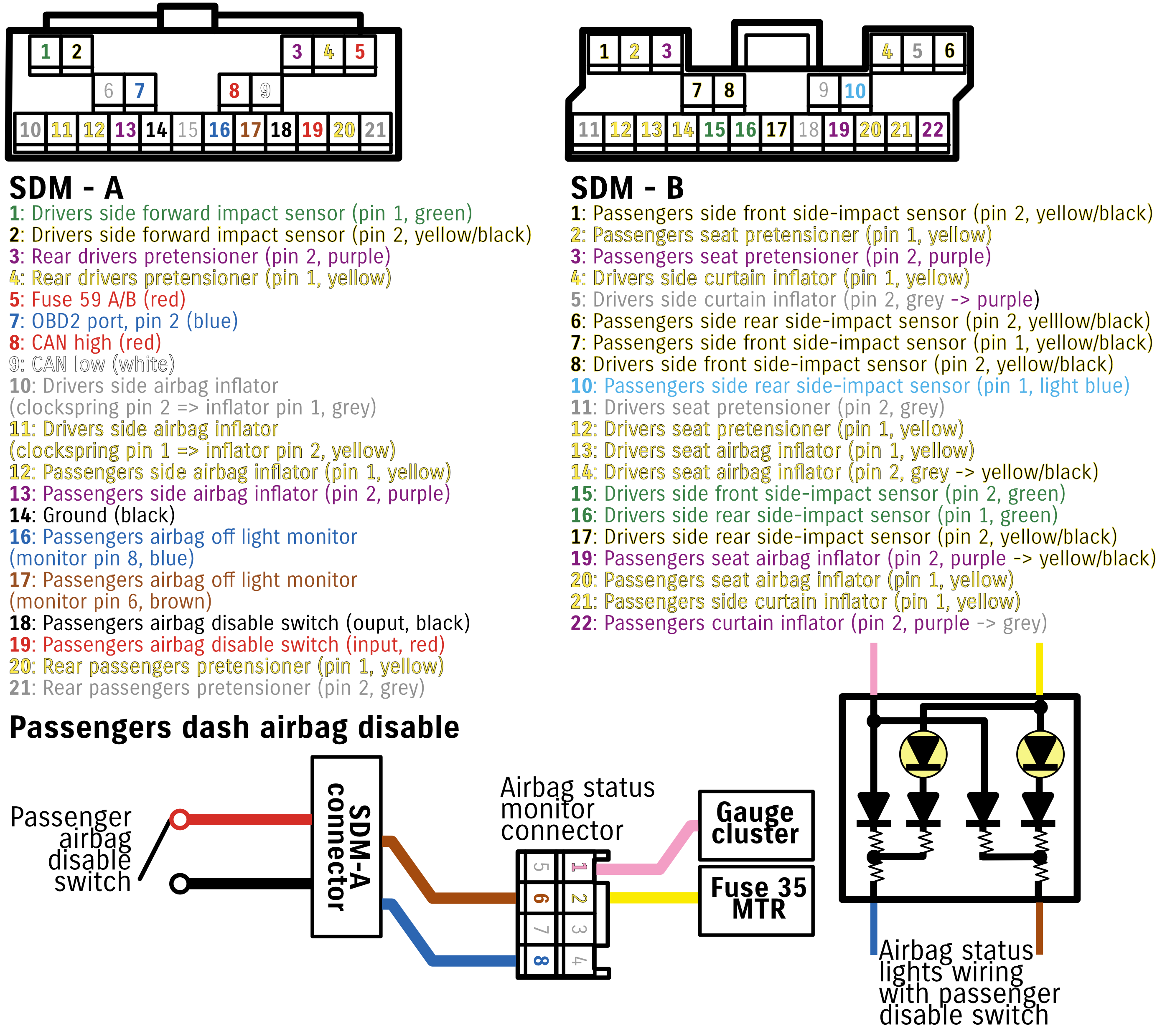
I’ve included the wiring for the passenger airbag disable switch. This is including in Euro models (I think), but isn’t included for other modules. The airbag status monitor is also unique to models with the ability to disable the passengers airbag, so I’ve included that in terms of the wiring so you can replicate it.
Note that disabling the passenger airbag only disables the in-dash airbag. Curtain and seat airbags on the passengers side will still deploy.
Washer bottle
Two connectors are the same as the indicators, though one is a black shell to distinguish from the other. I believe these are the front and rear washers. The other connector is a spade-style sealed connector, likely 6188-0259 on the motor side and 6189-0425 on the wiring harness side.
Indicators
2 pin 90980-11019
DRL/fog lights
DRL 3 pin 6187-3231 and 6180-3241
Fog light is an H8-H9-H11-H16 connector; if you want to connect into it then 6189-0935 is the connector to mate with the harness (I think).
Dashboard switches
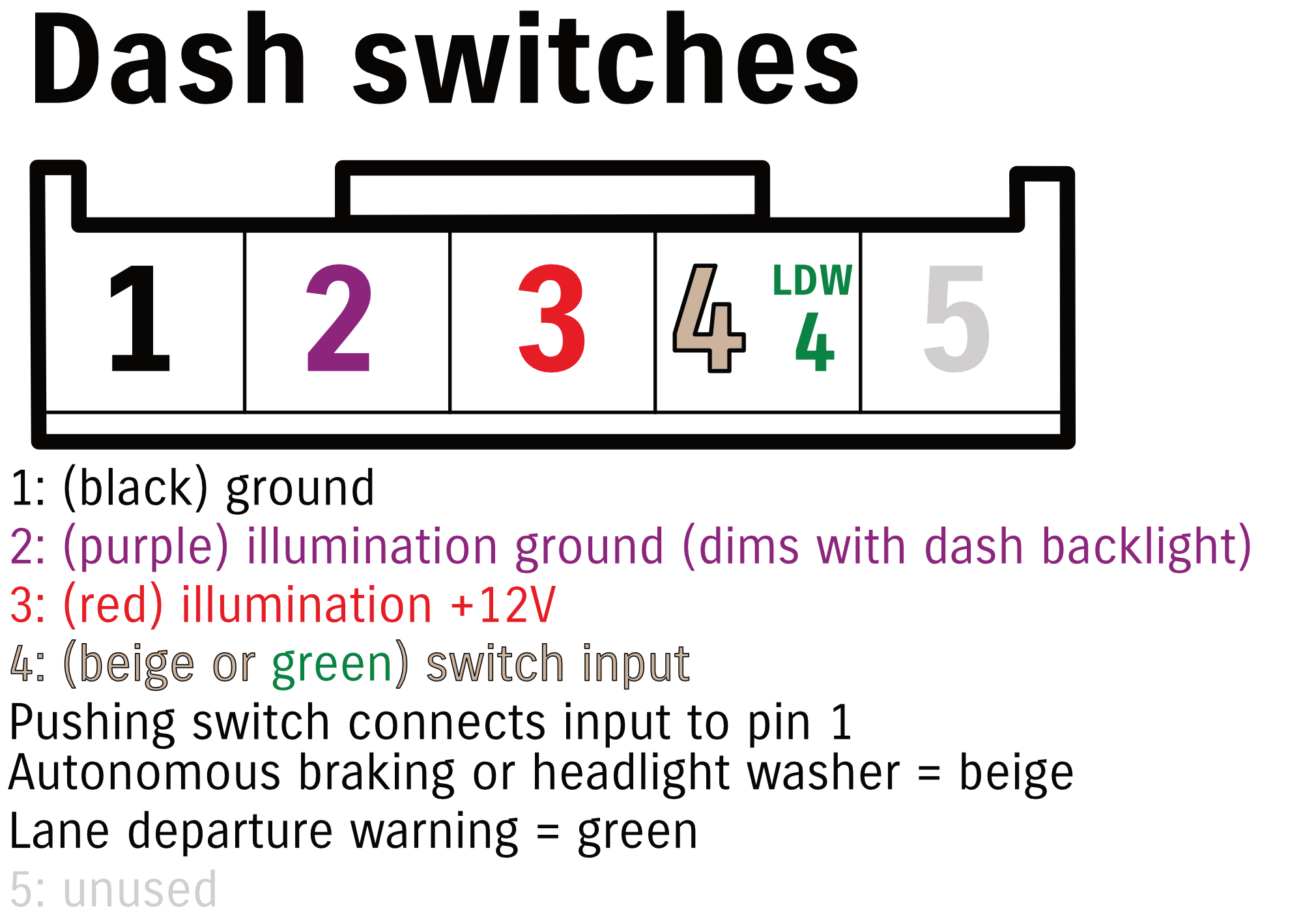
Connectors are 6098-3810 (plugs into the switch) and 6098-3802 (socket if you want to make up a piggyback harness)
Replacement dashboard switches (short Toyota)
JAE Electronics IL-AG5-5S-S3C1 (also matches reverse camera input to Bosch 7″ head unit) and IL-AG5-5P-S3C1
Headunit reverse/park/handbrake
Yazaki 7283-5830 and 7282-5830
Horn
6189-0386 (and mating connector to this is 6181-0227)
Single pin = positive, comes from the horn relay.
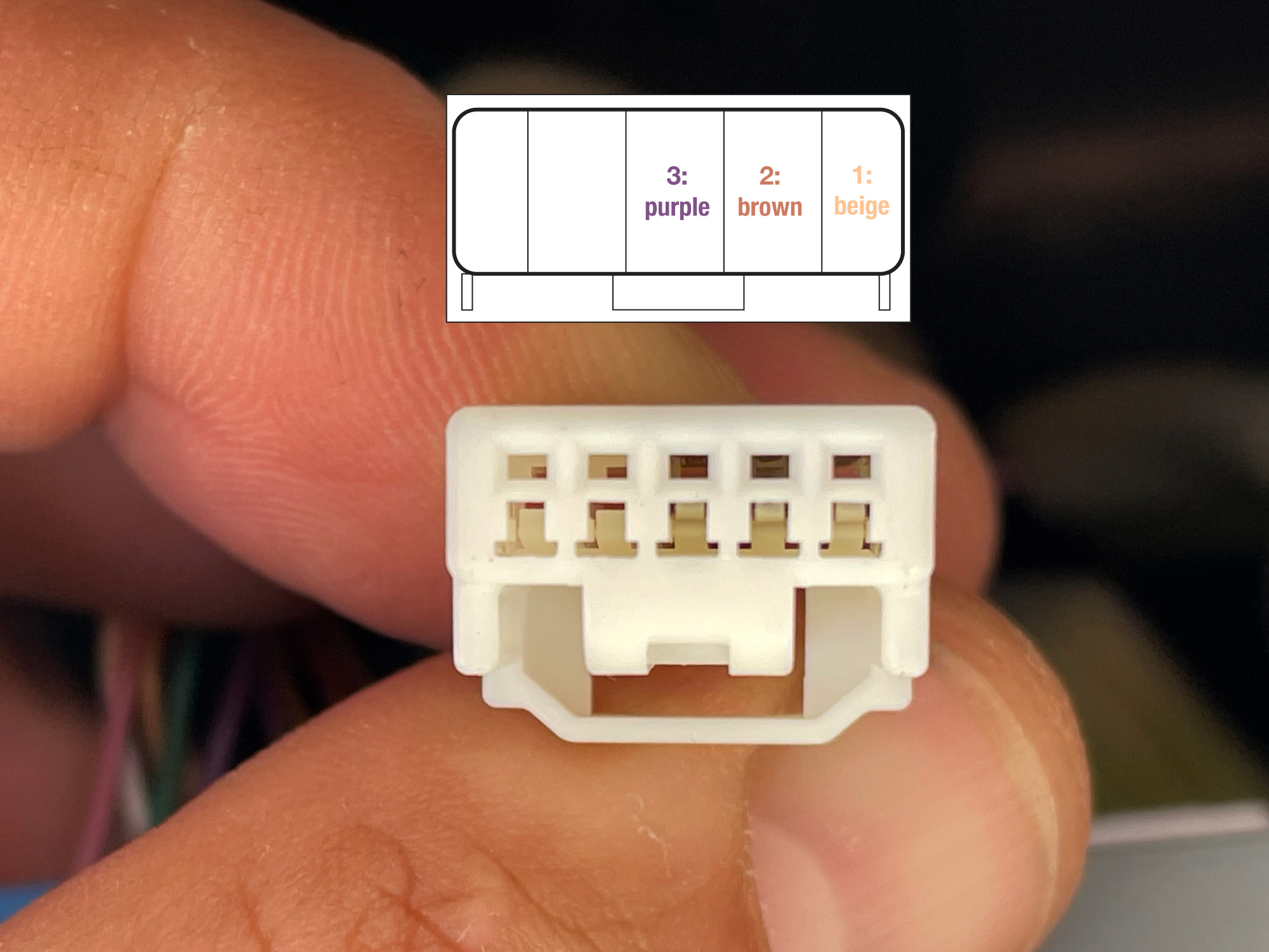
Interior lights
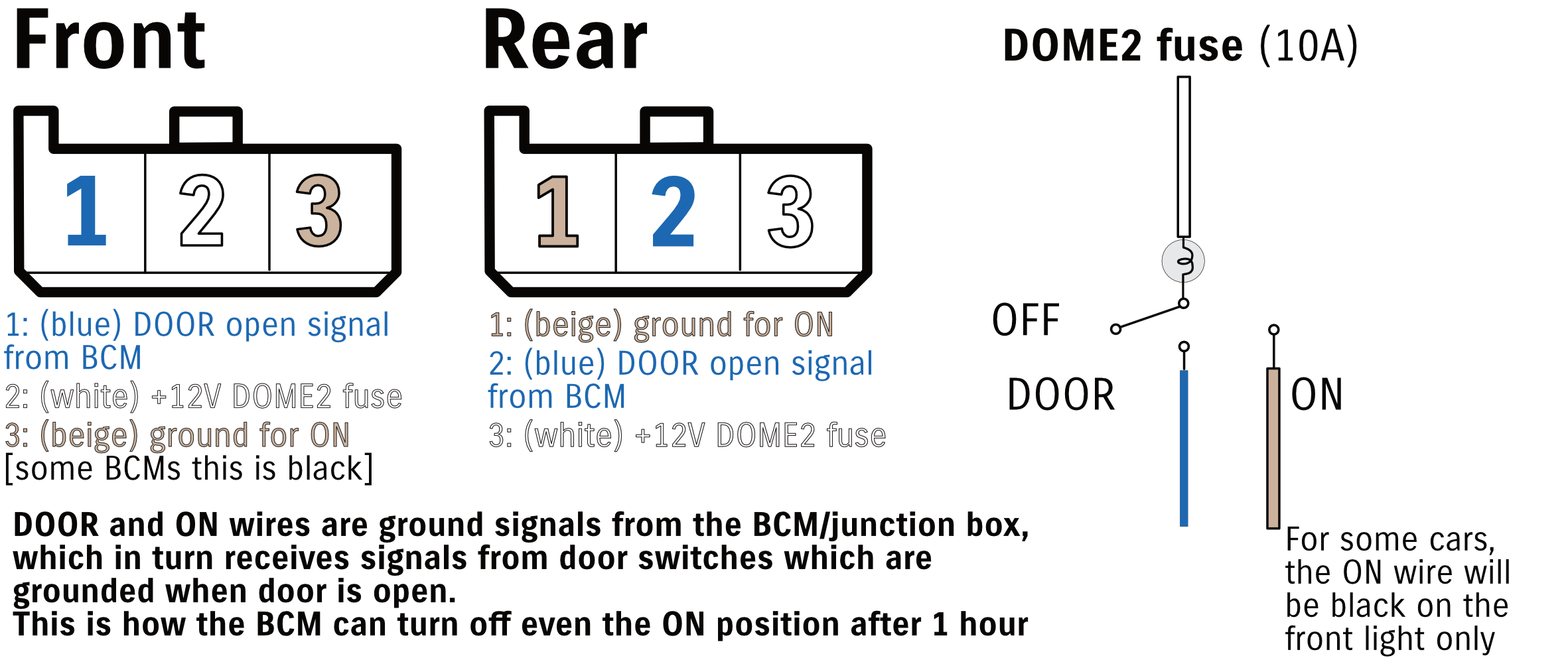
The wiring is pretty typical semi-modern car interior light. The light is essentially negatively switched and receives permanent power via the white wire. The beige wire gives a ground for the ON position, and the blue wire is grounded only when one door is open.
Note that both the blue and the beige wire eventually run back to the junction box/BCM. This is how the car can do some control things on the lights, like fading out the door light after a period of time from when you’ve got into it. It will also shut off the ON position for the light after a period of time. Note that the wire colours change for some cars for the front connector, and that the pinouts are different between front and rear.
I think the wiring on the wiring harness is Yazaki 090IIU-3S-1, with OEM part numbers of 6520-0577 or 7283-1030; the mating connector if you were to make up a piggyback harness is 090IIU-3P-1, aka OEM part numbers 6520-0492 or 7282-1030.