
Black Raptor/JimnyBits 2″ Lift Kit Install
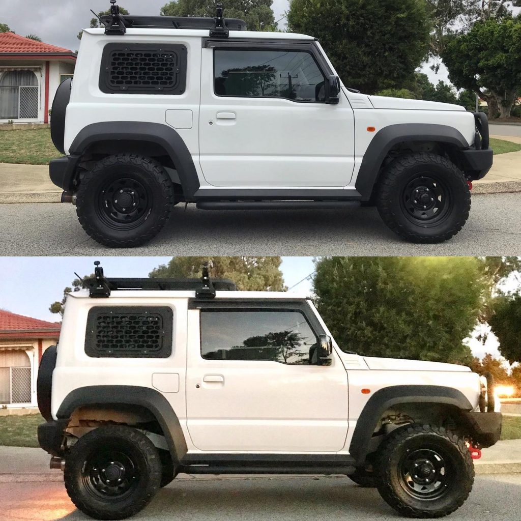
How it compares to standard
Sections
- Stuff you need to know
- Preliminary stuff
- Front install
- Rear install
- Caster correction
- Caster correction via offset bushes
- Caster correction via replacement radius arms
- Do I need caster correction at the rear?
- Extended bump stops
- Rear panhard relocation bracket
- Shortened swaybar end links and mount relocation
- Steering damper
- Do you need to do a wheel alignment?
- Technical stuff
- Standard versus lifted heights
- Brake line lengths
- Spring rates and lengths
- Shock dimensions
In a way this guide is something that isn’t brand specific. Certain lifts for the JB74 have different parts but the basics are the same: springs, shocks, +/- caster correction and brake line swaps. Then there’s some other aspects: headlight levelling adjustment for 3 doors with LED headlights and auto levelling headlights; rear panhard relocation bracket for adjusting some handling characteristics; swaybar relocation/shorter end links for better off-centre steering response; extended shock brackets to increase droop; bump stops for certain choices around tyre fitment. I won’t cover all of that, since I haven’t necessarily done all of that, but I’ll try to go through everything you’ll need to know.
Stuff you need to know
There’s a couple of difference to the previous models. You need longer brake lines if you go beyond about a 45mm lift at the front at least, and also drop the crossmember underneath the front driveshaft if you go above 50mm. Some people report with shorter lifts and caster correction that they also need to drop the crossmember (or remove it). We’ll discuss that in the front installation info.
Certain things about a lift can be regarded as optional. Caster correction, for instance, doesn’t appear to be essential as it depends where you car was standard w.r.t. caster. Wheel alignment also is simpler than many people make out. Panhard rod adjustment to centre the body on the chassis also depends on how that is from the factory: if your car is offset one way and you lift it and it gets worse you need it, but if your car was offset the other way and lifting it corrects it then happy days.
Is it essential to lift?
No. It does improve the stability of the car to improve the shock absorbers and if carrying any weight then the slightly stiffer and taller springs of a lift is also super useful in those situations. I had this lift kit sitting under my bed for ~18 months before fitting it because finding a day to document fitting it wasn’t easy… and the car was more than capable without a lift.
It looks way better with a lift, though.
If you want some guidance on what lift to buy then I cover that in the recommended mods section of this website.
You can upgrade suspension without a lift: there are multiple standard height targeting shock absorbers and they alone will make the car handle better. You are 95% of the way towards installing a lift when you pull out the shock absorbers, though.
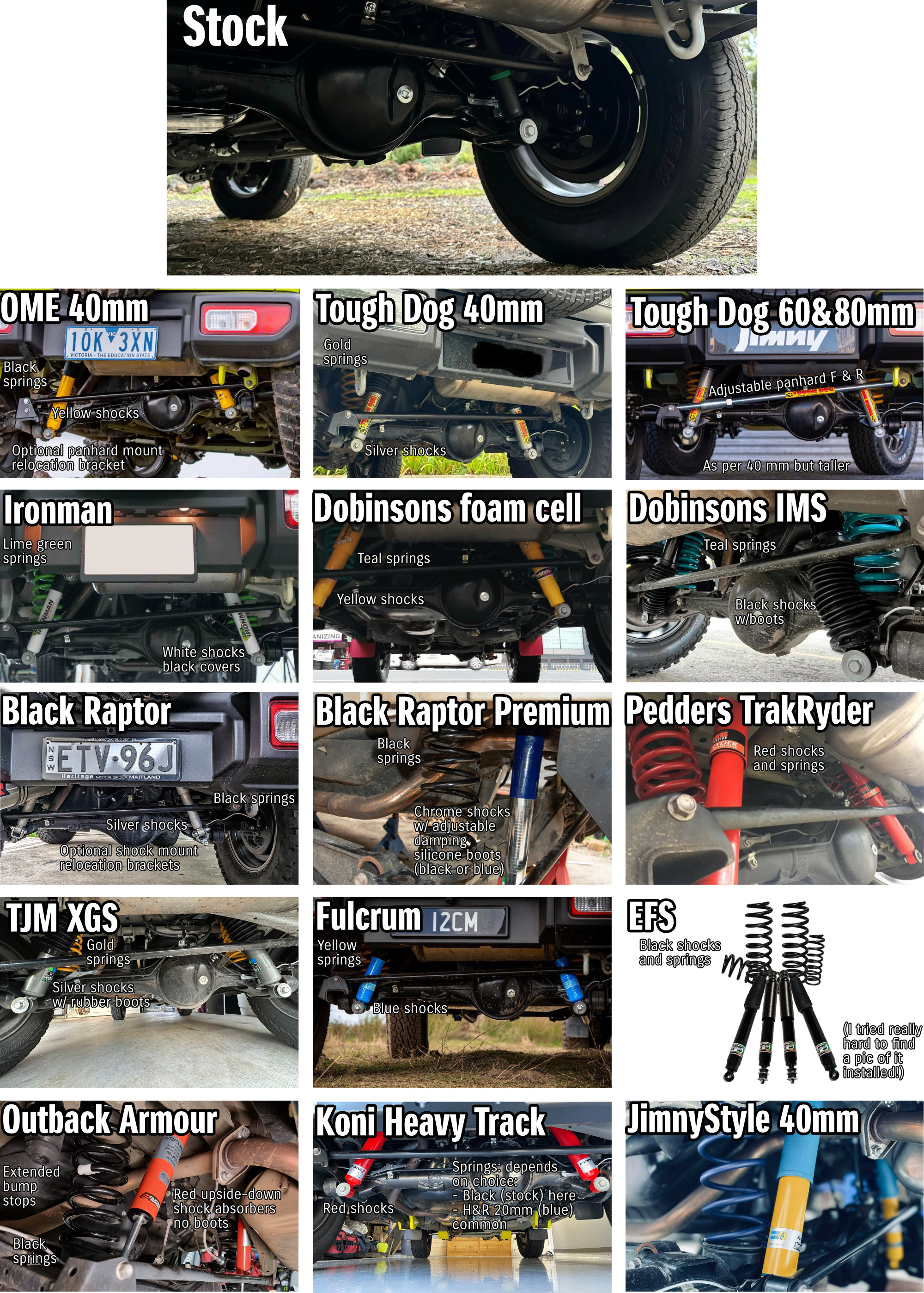
Why this lift kit?
I wanted to do something different to what people were doing when I bought the car, which was either a Tough Dog lift (for all the stuff it comes with & multiple height options) or an ARB/OME lift (because it was engineered to suit the car in conjunction with Suzuki Aus). Since I bought it other lift kits have come onto the market including the Ironman GVM upgrade, and a number of other brands e.g. Dobinsons, EFS, Pedders, yada yada yada.
I also really like DIY stuff (obviously, given this site) and I wanted to do it myself to write it up to demystify lifts for people & also demonstrate how easily it can be done at home.
What tools and stuff do I need?
- Jack
- Four jack stands
- 8, 10, 14, 17, (19mm) spanners
- 10mm flare nut wrench for brake pipes if changing brake hoses
- ~6mm or small shifter to hold the top of the front shock absorbers to tighten them up
- 22mm and 24mm spanners or large shifters to adjust draglink
(locking nuts on adjusters are 24mm, drag link flats to hold drag link still when doing up jamnuts is 22mm) - 10, 14, 17, 19mm sockets, ratchet handle, and a long breaker bar to suit
- Torque wrench
- Stuff so you can bleed the brakes if you’re changing brake lines, like clear hose or a one-person bleeding kit
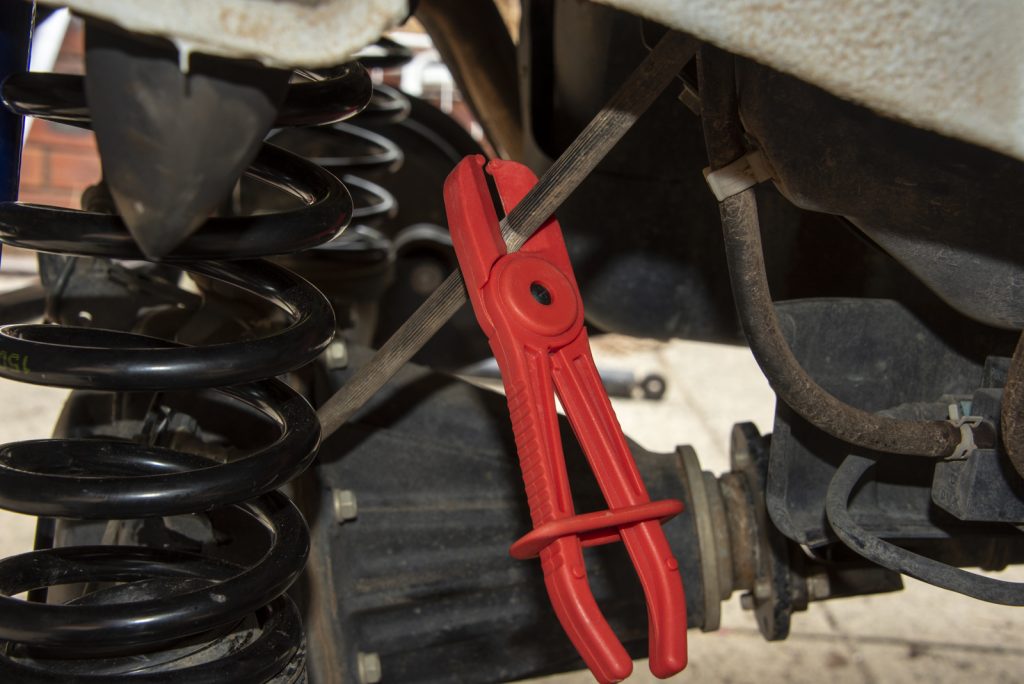
- Brake hose clamp to minimise fluid loss if changing brake lines
- Brake fluid if changing brake lines
- Needle-nose pliers or some other way to ping off brake hose circlips
- Potentially a small tiny file for any adjustments to the light bracket needed
- Some medium strength (blue) threadlocker for shock absorber bolts
Preliminary stuff
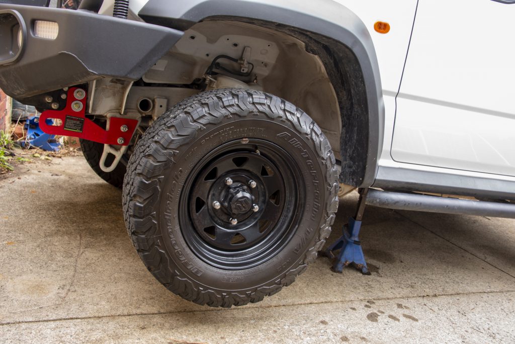
When doing this job, you need a fair amount of room underneath the car to drop the axles low enough to easily remove the springs. There’s also bonus points for having the car high enough that you can refit your wheels once you’ve lifted the car… the extra suspension down travel of longer shock absorbers can make it challenging!
I didn’t actually get mine quite high enough with the jack stands I have and that’s ok, just requires jacking up under the axle to lift it up a bit against the suspension before you refit wheels at the end… but if you get it high enough then you save that bit of time right at the end when you just want to get inside and have a nice refreshing beverage.
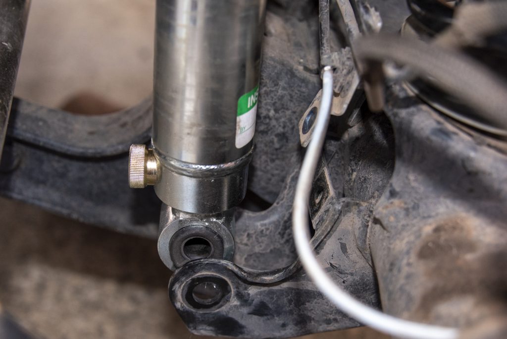
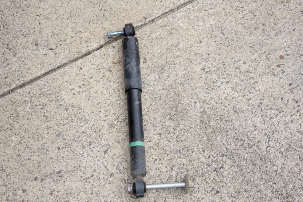
The kit I have bought – the Black Raptor premium 2″ lift – comes with adjustable shock absorbers. I set these to the middle of their adjustment settings and will play with them and report back suggested settings after some time with the car. They have a dial on the bottom of the shock that you turn right or left and it clicks for each of the adjustment points. Easiest way to find the middle is to turn it all the way loose, then count the clicks to all the way tight. Then turn it back half those clicks to the looser setting.
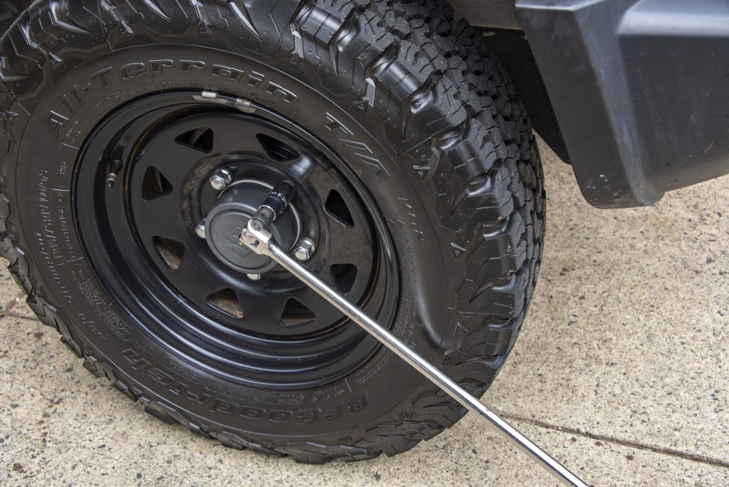
Before you lift the car though, loosen the wheel nuts. This is way easier with the car on the ground.
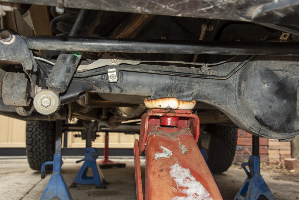
Once the wheel nuts are loosened a little, lift the car up by the chassis and support it with jack stands under the chassis rails.
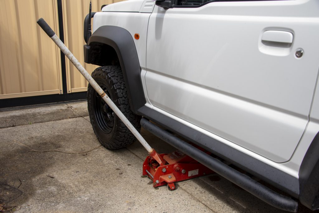
I find it’s sensible to lift the front first with the handbrake on to stop the car rolling back as you lift it, and then lift the back. When lowering it afterwards reverse this procedure.
With that done it’s time to get with the installation. I did the rear first then the front but I’ll write it up front to back
Front
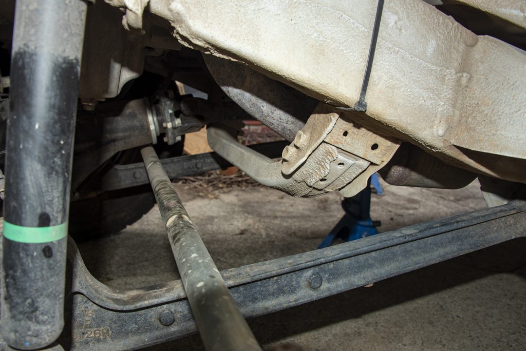
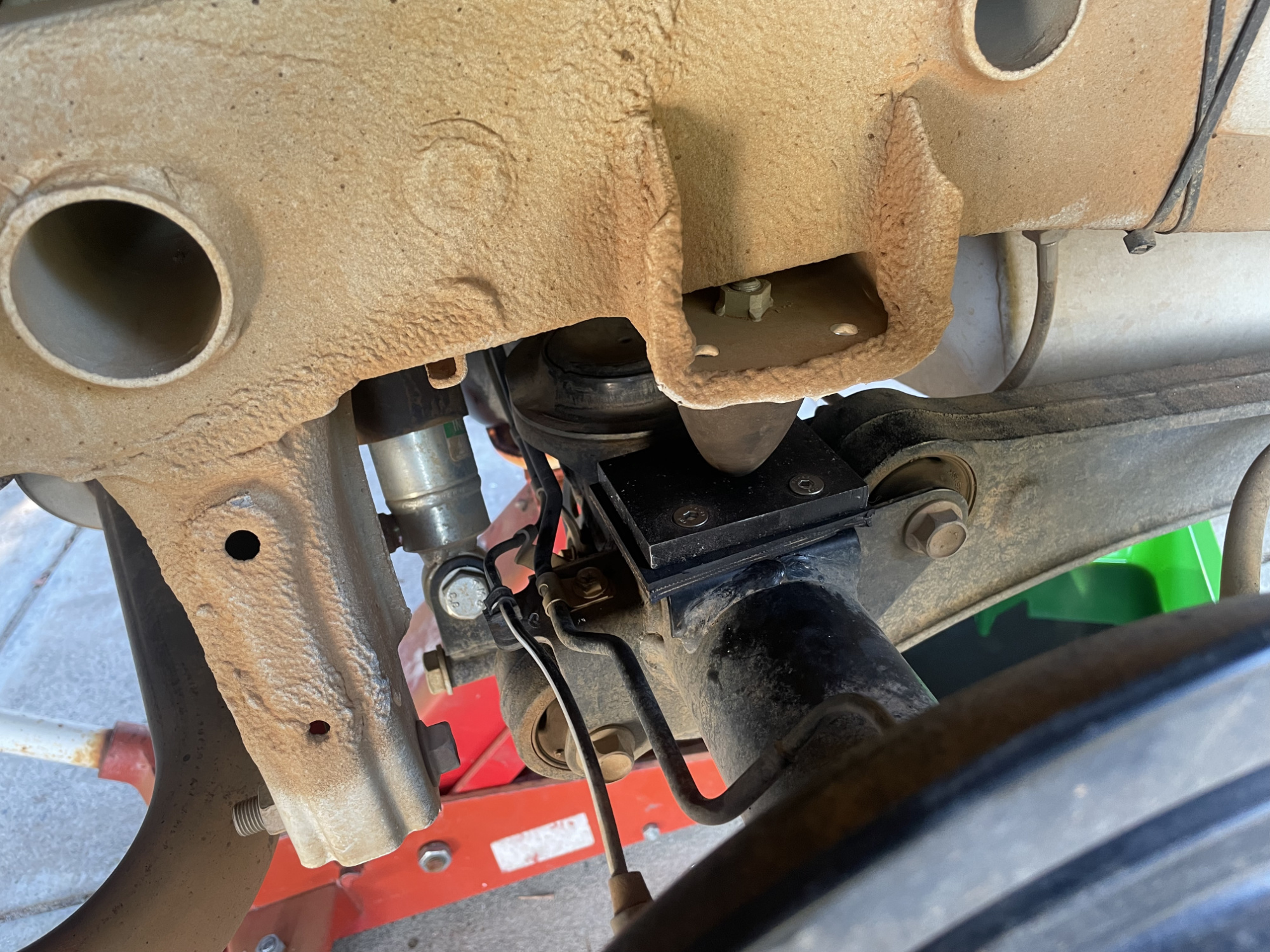
The front is quite straightforwards, and I think the sensible thing to start with is to remove the crossmember that runs underneath the driveshaft. If you are fitting a small lift (< 50mm) this isn’t required to be changed for a lower one, but you will hit the front driveshaft against it as you lower the axle to remove the springs anyway. On the other hand, if you are running a lift of ≥ 50mm then you need to either remove it or run a crossmember with increased clearance so might as well get it out of the way now.
The crossmember comes out with two 14mm bolts/nuts each side. The bolt heads can be coated in anti-rust stuff so might be a challenge to get a spanner on to hold them when you undo the bolts. In the below pic I show the heads of the bolts and their anti-rust coatings… the nuts are on the other side of the crossmember but fairly obvious.
The JimnyBits 2″ kit comes with a complete crossmember to replace the factory one.
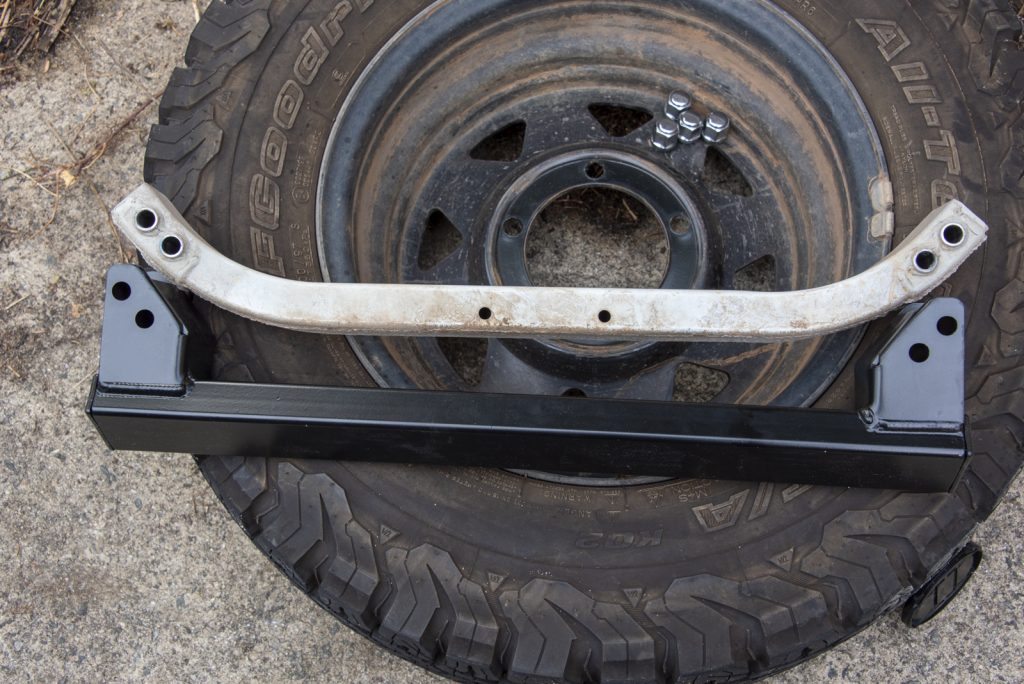
Some other lift kits come with brackets to drop the factory crossmember, and some people just don’t use it. This crossmember basically stiffens the chassis compared to a JB43 so it’s probably not *essential* but the chassis will flex more without one. There also exists a nice one which actually runs ABOVE the driveshaft, removing all clearance issues and also gaining further ground clearance.
Re-installation doesn’t really need a picture, but you tighten up the bolts. Not really difficult… torque isn’t specified in the manual but probably 59 Nm.
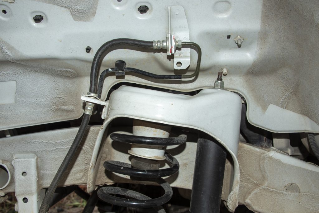
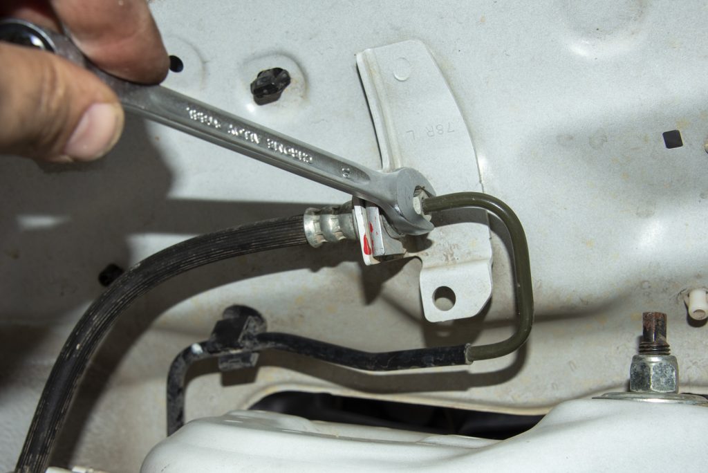
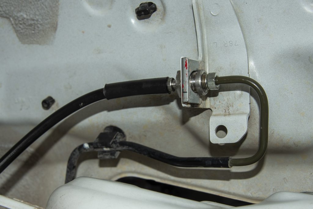
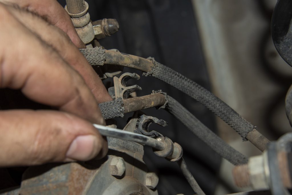
The next thing you need to do is release the brake hoses a bit. If you aren’t replacing them you don’t need to fully remove the hoses but unclipping the middle connector helps a heap with lowering the axle.
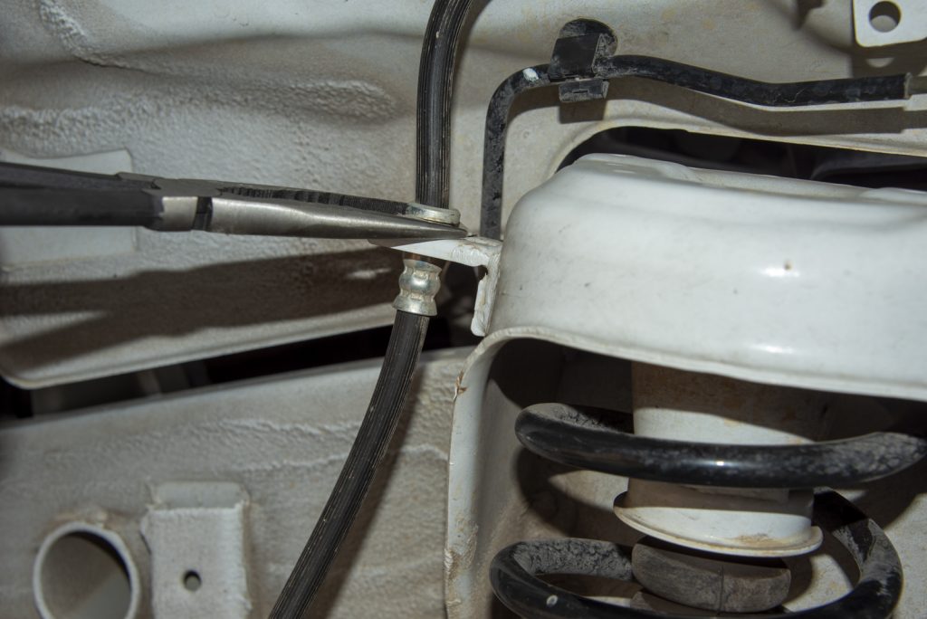
Undoing the circlips holding the brake lines to the body can be frustrating, but if you use long handled pliers and squeeze them with one end against one of the ‘tongues’ and one against the metal part of the brake pipe they end up getting pushed off. They can fly off at great velocity though…
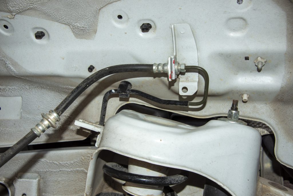
With the clip released out of the middle holder at the front, you can then push the hose down a bit and then it comes out of a slot in the mount while remaining connected at the ends still.
If you’re changing brake hoses now is the time to do it. The way I like to do this to minimise fluid loss (and hence the amount of time I need to bleed the brakes after changing the hoses) is:
clamp the existing brake line
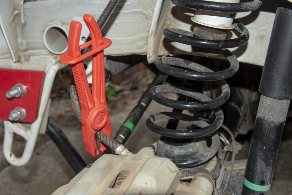
get the lines slightly cracked at the bolts (don’t judge me for not using a pipe/flare nut spanner… I would suggest doing so)
then undo the circlips just like above
undo the caliper end bolt noting it’ll start pouring fluid out from the caliper as soon as you do this
immediately fit the new caliper end bolt with its new washers to stop the fluid coming from the brake caliper
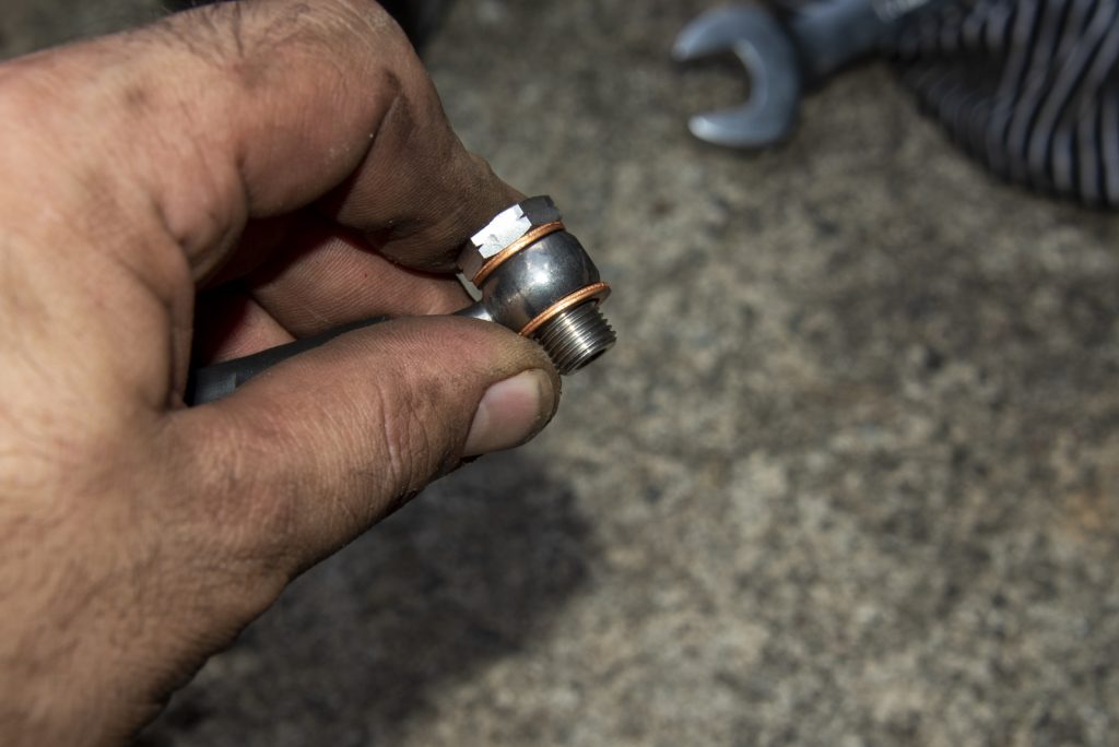
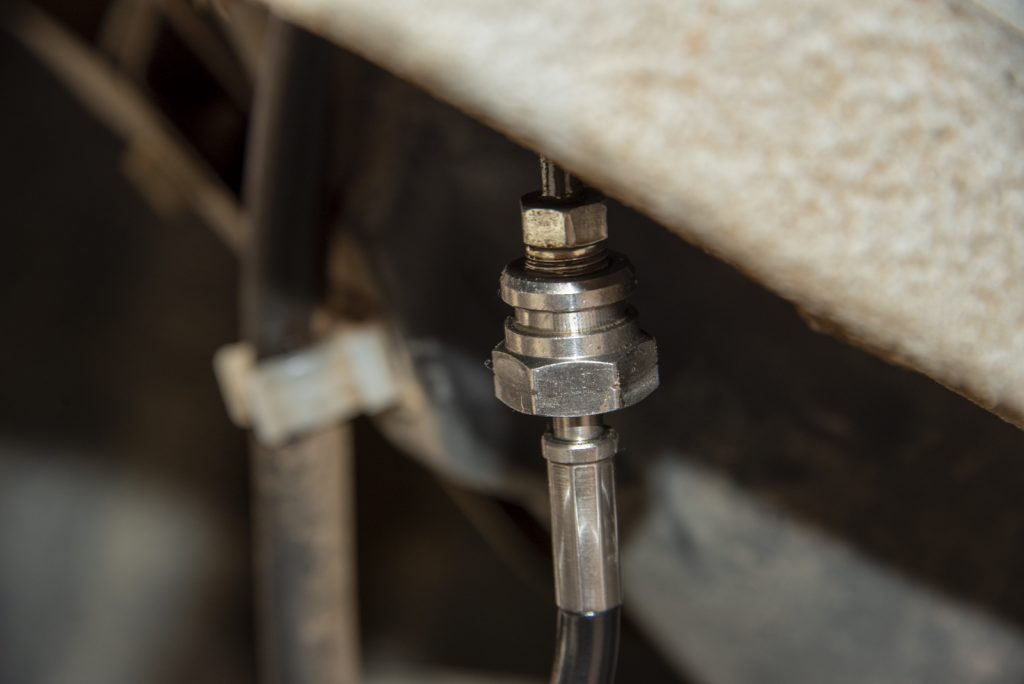
undo the upper hose nut, which will start pouring fluid everywhere (hence no picture), then immediately fit new brake hose to upper pipe connection, and tighten up with a 10mm flare nut spanner on one side and a 17mm spanner on the other if you’re using typical replacement brake hoses. Then it just clips onto the factory mount as per the original.
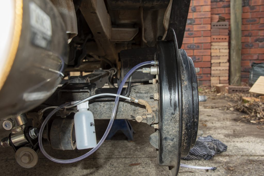
With the brake hoses swapped it’s a good idea to bleed the brakes. I actually did this for each side as I went rather than trying to do it all at once at the end.
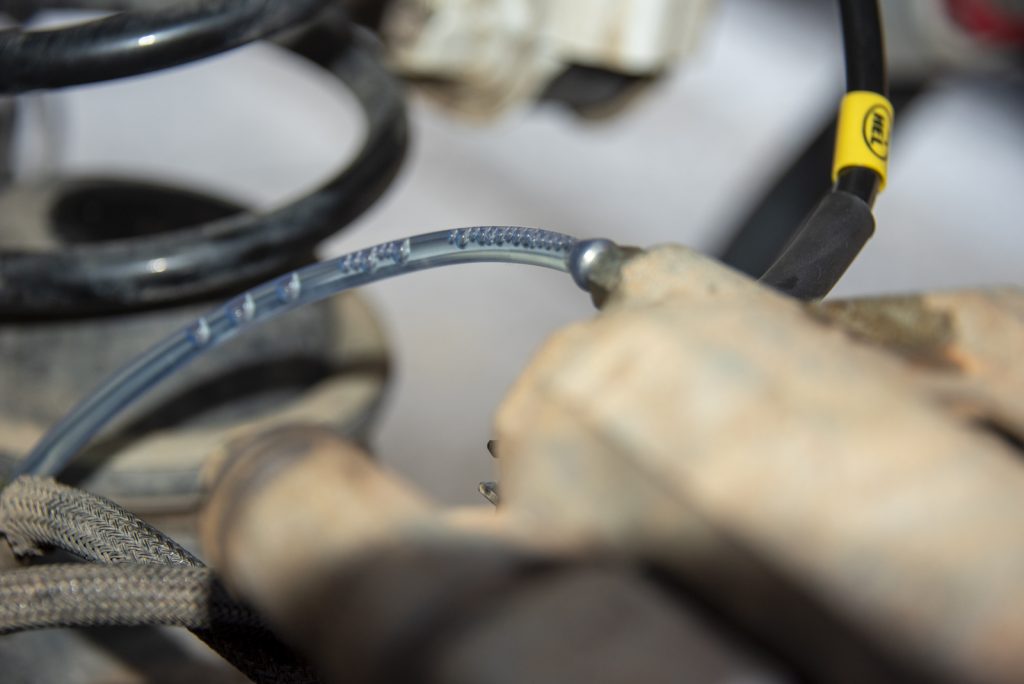
Bleeding is quite simple, I used a one-man bleeding system from Supercheap although there’s lots of options here. You only are introducing air pretty close to the caliper itself so it’s fairly easy to bleed and it does essentially gravity bleed itself as you do it.
Start by putting your chosen bleeder setup on the bleed nipple for the caliper you just swapped the brake hose on. With the hose on, undo the bleed nipple (10 mm on the front).
Air will start coming out first so you won’t see any fluid. You can actually just leave it for a while here till you start seeing both fluid and air coming out.
Once this has started you can give the brake pedal a bit of a pump to force more air and fluid through. Go all the way down with the brake pedal in nice smooth and steady pushes. Note that with the engine off the brake pedal with have a lot more resistance than you’re used to feeling, but with the bleed nipples undone the pedal will go all the way to the floor.
Once you’ve done that a bit and there’s only fluid coming out of the nipple, tighten up the nipple and you’re done with that side. Clean up the split brake fluid with brake cleaner or water or similar.
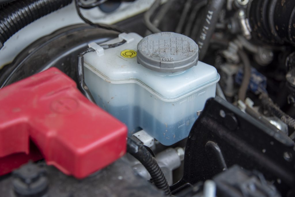
Don’t forget to periodically top off the master cylinder reservoir with fresh brake fluid. Don’t run this out, it makes the whole process a lot harder!
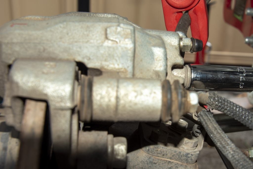
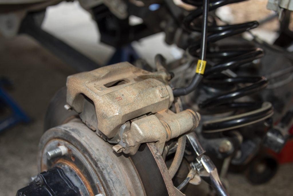
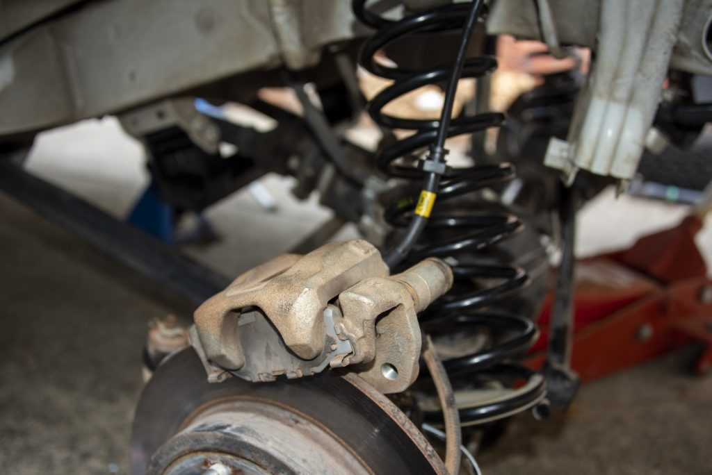
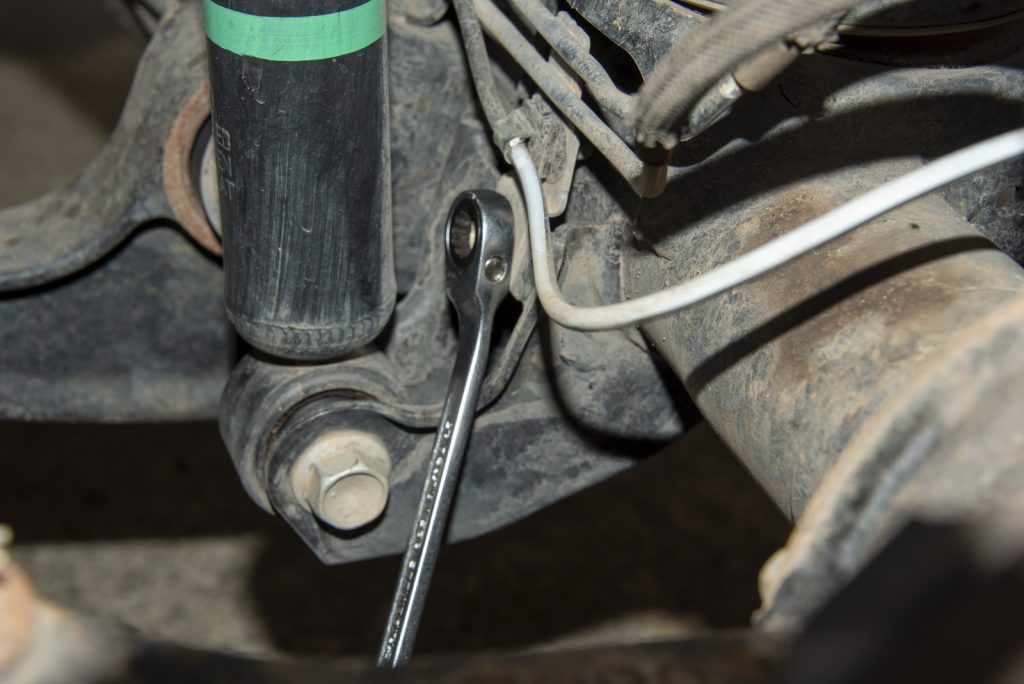
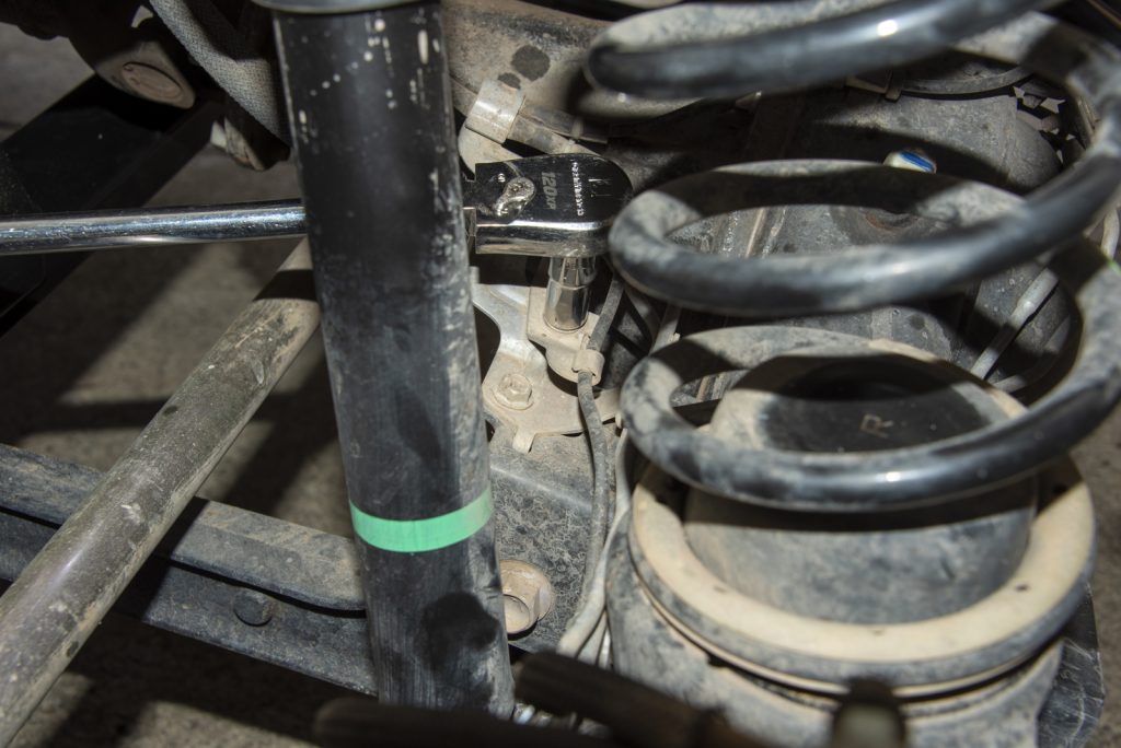
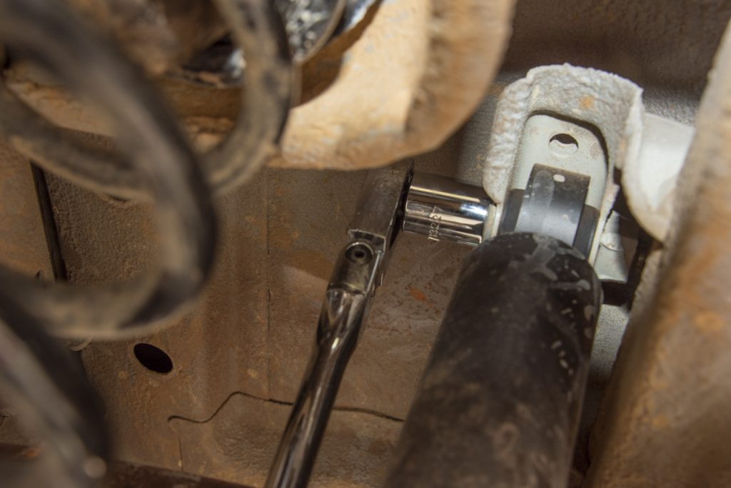
I also found that I needed to partly release the brake calipers from their mounts to get the axle low enough. This isn’t too hard, you just undo the ‘front’ bolt completely, and loosen the back one a little, and let the caliper rotate up. Hard to photograph from the back but release the lower of the bolts that mount the caliper to the axle itself, not the higher up bolts on the caliper which are the caliper slide bolts. The position of my ratchet here gives away what bolts to undo.
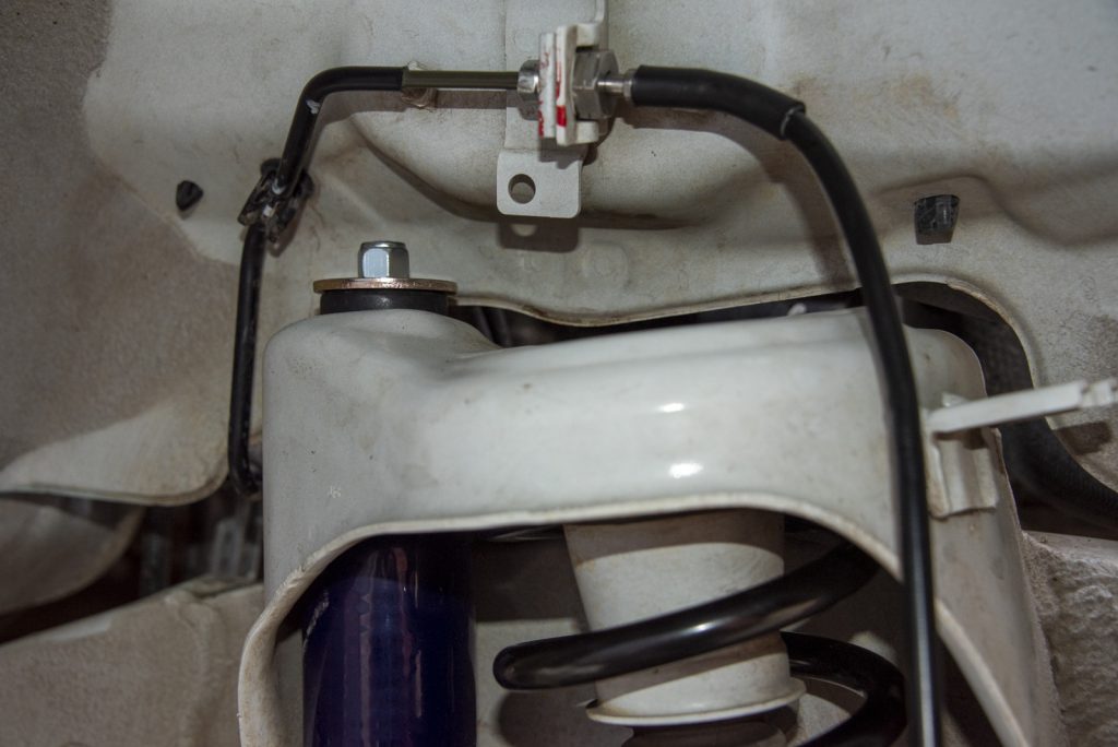
Before lowering the axle you need to support it underneath with your jack and remove the shock absorbers. With the axle *just* supported, either undo the top or the lower mount… top is probably easier to get to, bottom isn’t terrible either.
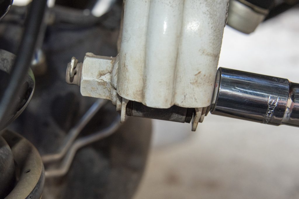
Top is undone by holding the small flat sided rod with a really small spanner, and a 14mm spanner undoes the nut. Bonus points if you use a ratchet spanner here but it’s doable, albeit slower, with a normal spanner.
Lower mount is 17mm on both ends. The back side is a nut which is very close to the radius rod so you’ll need a spanner in there to hold it. The bolt head is pretty easy to get to with a ratchet with a socket on it, though.
For refitting, what I found easier was to put the new shock into the lower mount and do it up finger tight, and then change out the spring.
Then when you lift the axle back up against the spring, line the shock up and put the top nut on. It can be tricky with new bushes as they need a lot of squishing down, just start the nut very carefully so you don’t cross thread anything.
Lower shock bolt is torqued to 60 Nm, upper nut is 35 Nm but without a crows-foot spanner you will struggle to get a socket in there to torque it up. I always like to do these with suspension loaded i.e. jack up the car till it is just about to lift off the jack stands under the axle, and then torque up the bolts.
With the shocks released from the top (now you’ve refitted the shocks at the bottom mount) you’re almost ready to lower the axle, but first a few things need to come off.
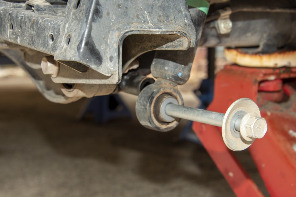
The workshop manual suggests releasing the panhard rod at the body side. I’m not sure this is necessary but I did do this. Undo the clip on the bolt and then undo the 19mm headed nut. Note this is done up really right so use a long breaker bar to undo it.
The other thing that makes sense to do is to undo all of the mounts on the right hand side (drivers side for Australians!) that hold the hoses to the axle where they come down from the body. This gives you enough wiggle room to lower the axle and get the springs out without straining any hoses. You don’t need to disconnect everything, just the 4 10mm headed bolts that hold the various brackets to the axle. You also want to just release the wheel speed sensor wire, and the two vacuum hoses, from their little clamps at the back of the caliper.
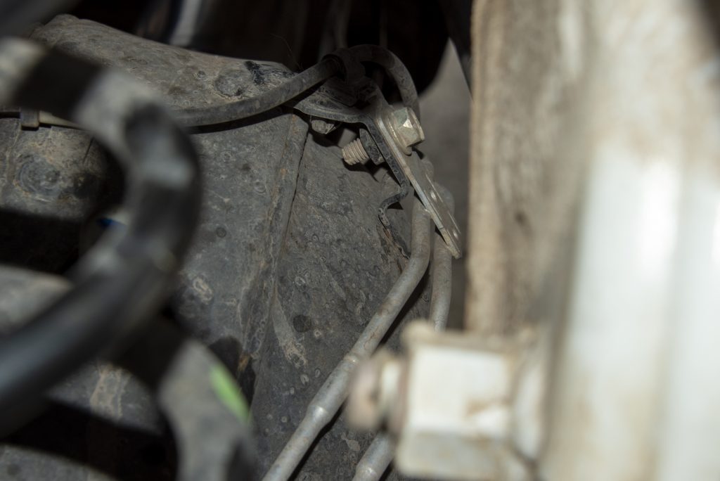
With those four bolts and hoses/wire unclipped from the back of the right hand side caliper, there’s enough slack to let the axle lower as you lower it with shocks disconnected to get the springs out. You only have to do this on the right hand side because that’s where the vacuum hoses and wheel speed wires come from.
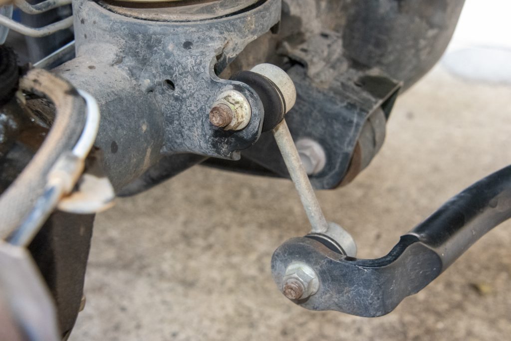
The final thing to release is the swaybar end links. Bit of a pain to do this with a ratchet but probably doable, in my case I used an impact gun to just buzz them off which worked a treat. Slightly easier to access the lower of the bolts i.e. right on the end of the swaybar. Disconnect the swaybar at both ends.
Before you lower the axle and release the springs, a bit of a checklist
- Axle lightly supported underneath by jack.
- Crossmember removed and (if required) replaced with dropped crossmember.
- Brake hoses released from intermediate clips and (if required) replaced with extended hose. Caliper front bolts undone, rear bolts lightly released so caliper can pivot.
- Shock absorbers released from their top mounts, potentially replaced with new shocks attached only at the bottom mounts.
- Vacuum hoses and wheel speed sensor wires unclipped from back of right hand caliper, and mounts on right hand side holding hoses released from axle housing.
- Panhard rod disconnected at body end.
- Swaybar ends released from axle housing.
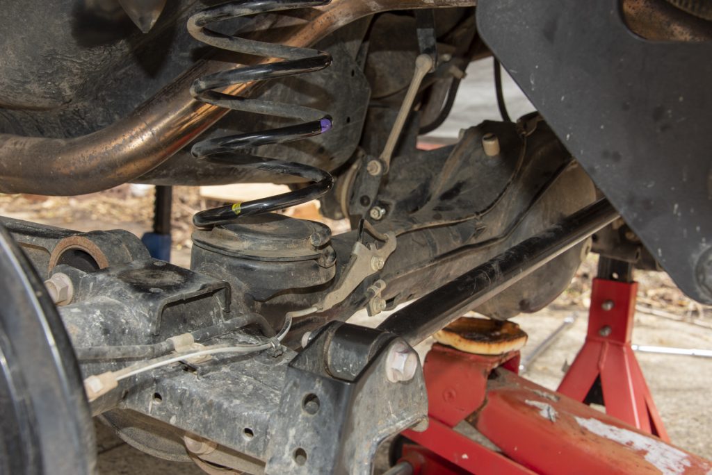
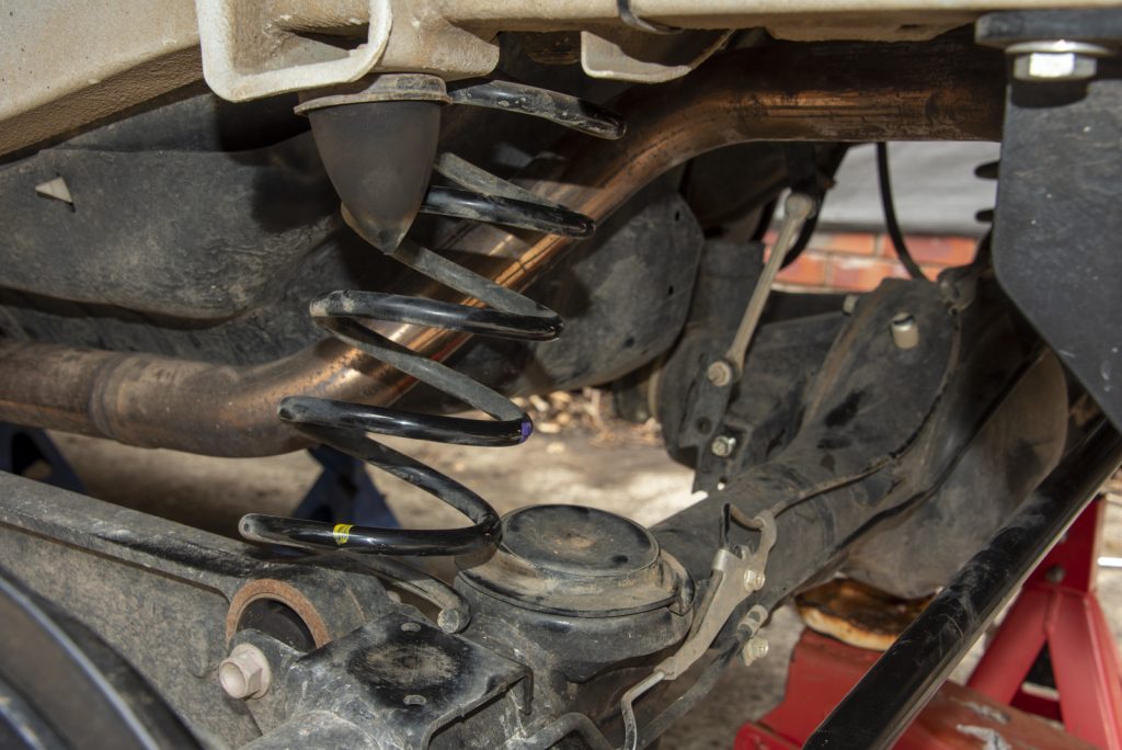
With that done you’re now at the easy part! Release the jack and slowly lower the axle. You’ll eventually get to the point where the springs just can come out.
Once the old springs are out, you can take the bottom plastic noise dampers from the standard springs and put them on your new springs. These just stop a bit of rattling.
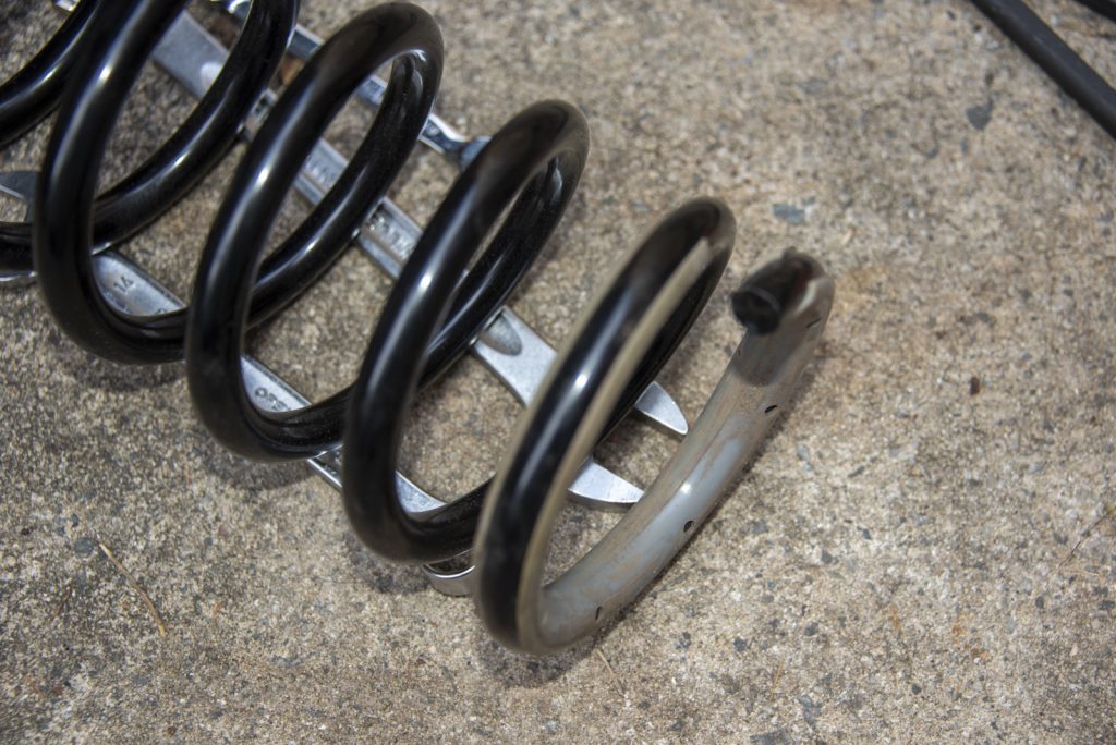
Note that my kit was an early one so I’m not sure it is representative of how they are supplied now… but mine came with zero instructions. There were 3 springs: two of the same length marked 1500, and 2 longer ones which were marked 1100 and 1000 respectively, with the 1100 one being a little longer than the 1000 marked one. My understanding is the equal length ones go in the back, and the 1100 spring goes into the drivers side and the 1000 spring gets the passengers side at the front. Easy peasy. I might be wrong, and it is different in that some lift kits run different rear springs rather than different front. In any case, that’s how I did it and it seems fine.
When you refit your new springs, get the spring end at the bottom so it sits between 0 and 10mm back from the ‘end’ of the spring seat. This ensures it isn’t sitting incorrectly (too high) on the axle, but also gives enough space for the corresponding end up in the top mount to sit correctly.
At that point you just lift the axle up and do up the shock absorber top mounts, do up the caliper bolts, do up the four vacuum hose line mounting brackets, and clip all the hoses into their correct position.
You can now do the swaybar end links, then tension up the shock absorber mounts. Then pull the panhard rod end back into place and tighten this up to 150 Nm.
One thing often overlooked here is to bend up the bracket for the wheel speed sensor wiring and vacuum hoses. At full droop these can be very tight and even rip which is an expensive time or a good way to discover you are either unable to engage 4wd or unable to disengage the front hubs. Just give it a bend up and check that there’s nothing being snagged at full droop.
After that then then it’s just checking everything is tight, putting the wheels back on and the front is sorted.
Rear installation
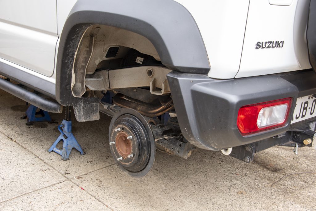
We start the rear off the same as the front: jacked up in the air, wheels removed.
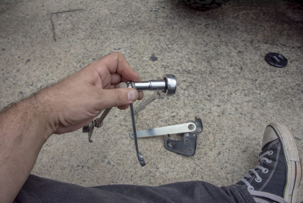
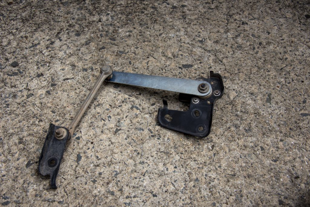
First thing to disconnect is the auto levelling headlight sender unit if you have them fitted (all Australian ones do). There’s 2 10mm bolts right at the top, a little clip to unclip the wiring harness where it attaches to the mounting bracket, a wiring connected that you have to push in a little tab with your thumb to remove it, and one 10mm headed bolt down where it mounts to the axle.
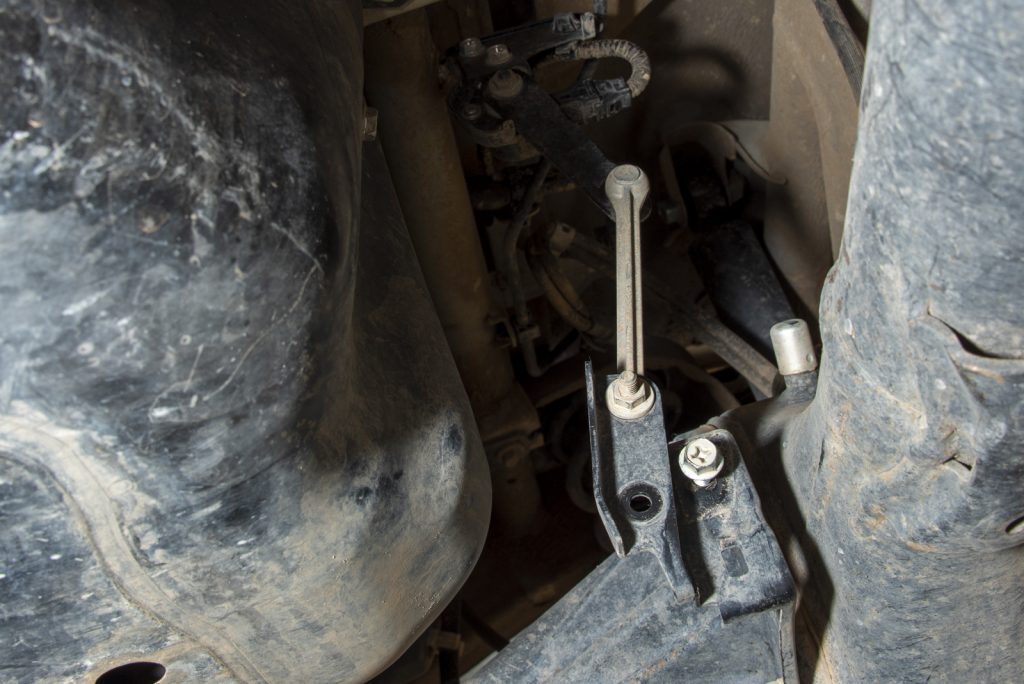
The reason you have to take this off is the bracket will bend as you lower the axle to release the springs. The other reason is that you need to account for your lift with the levelling system – kits should come with a bracket to offset this. The Black Raptor kit came with a replacement arm but I understand some others just lift the lower mount.
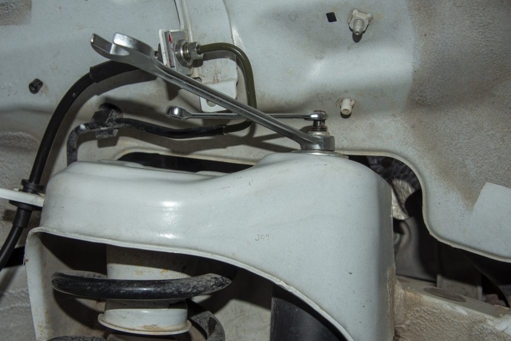
To fit the new arm, you push the arm all the way to rotate the sensor counter-clockwise and undo the nut to the sensor with a 10mm socket. This reveals the actual connection to the sensor, note it has a little curve on one side of the pivoting peg.
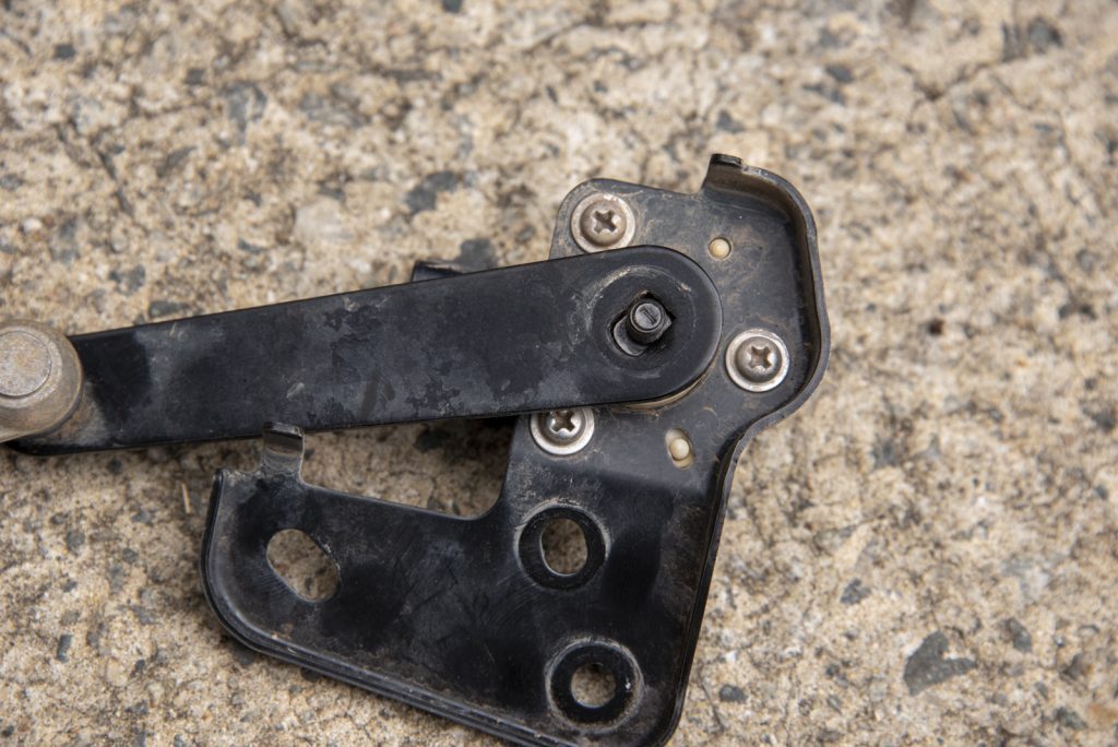
Undoing the other end of the pivoting arm requires both a 10mm socket and a 10mm spanner, or two spanners. The spanner holds the ball joint shaft, and then the other 10mm tool undoes the actual nut.
You then fit it all back together with the longer arm and one modified light levelling unit is sorted… don’t refit it till after you’ve lowered the axle and dropped the springs though!
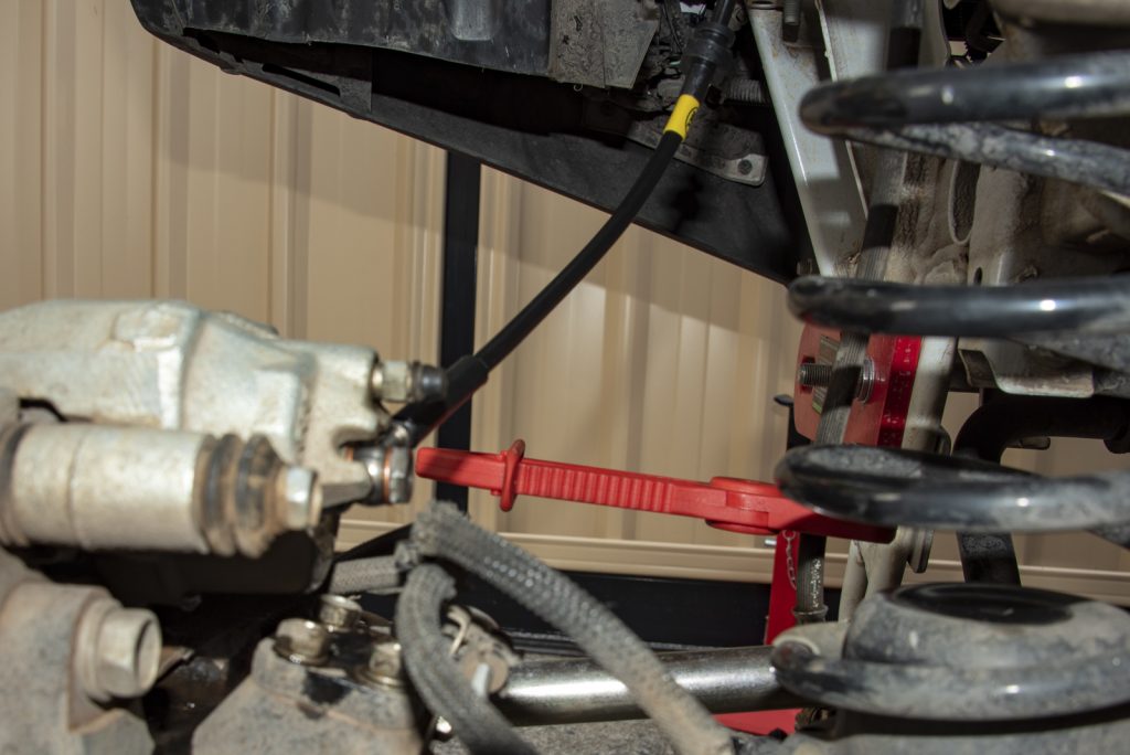
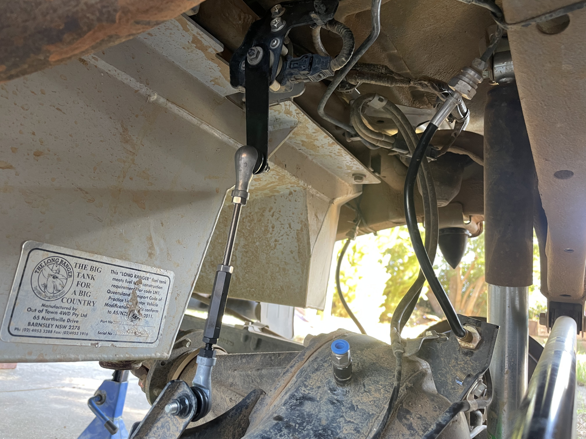
UPDATE! I have gone back to the standard headlight pivoting arm but I’ve replaced the linkage to the axle with an adjustable Taniguchi item.
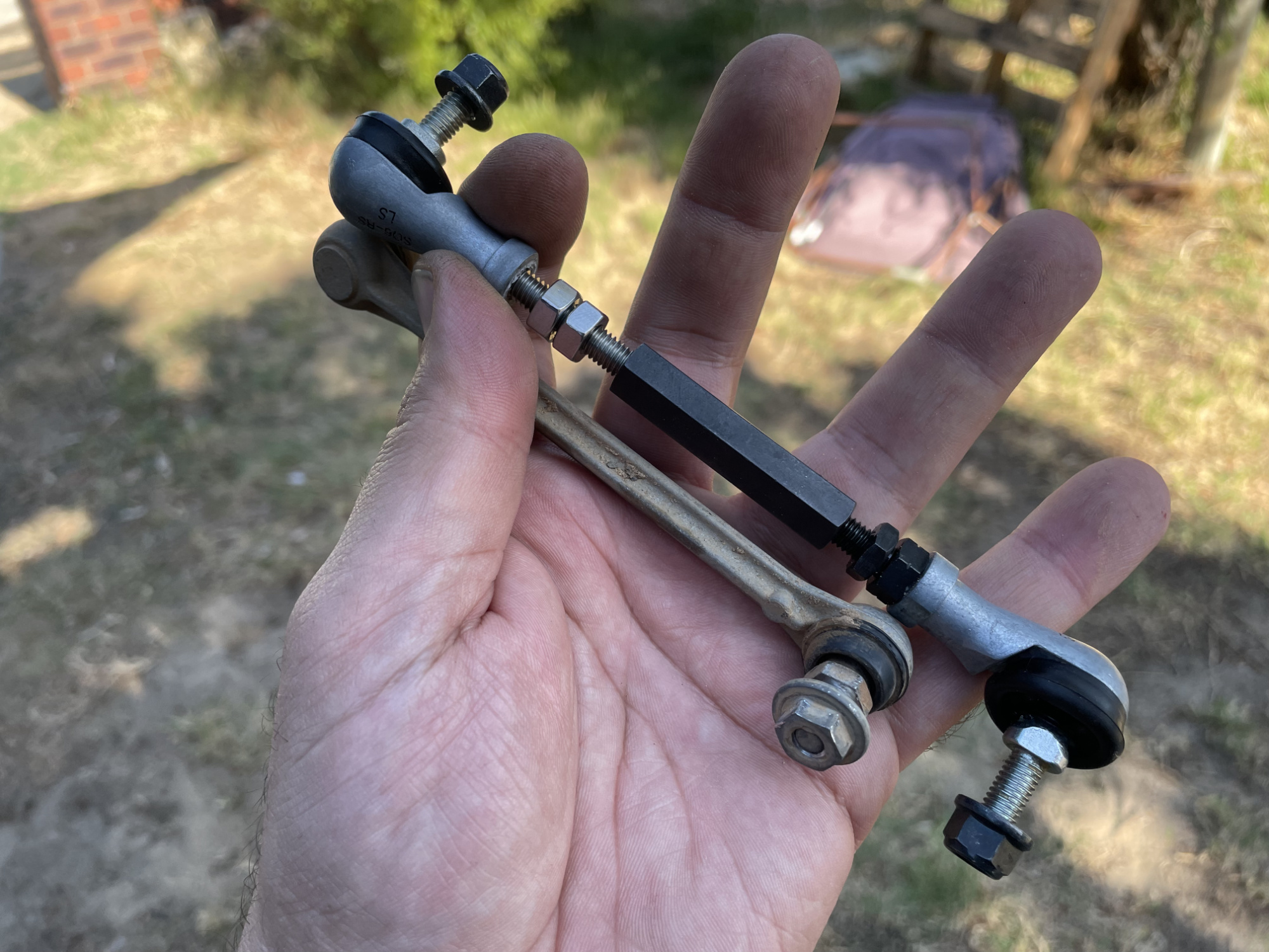
You need to use this with the standard headlight pivot arm, but the linkage allows you to dial in the perfect length for getting droop and bump positions perfect. With the extra droop in the rear that I have from running shock extension brackets this is necessary to get everything correct.
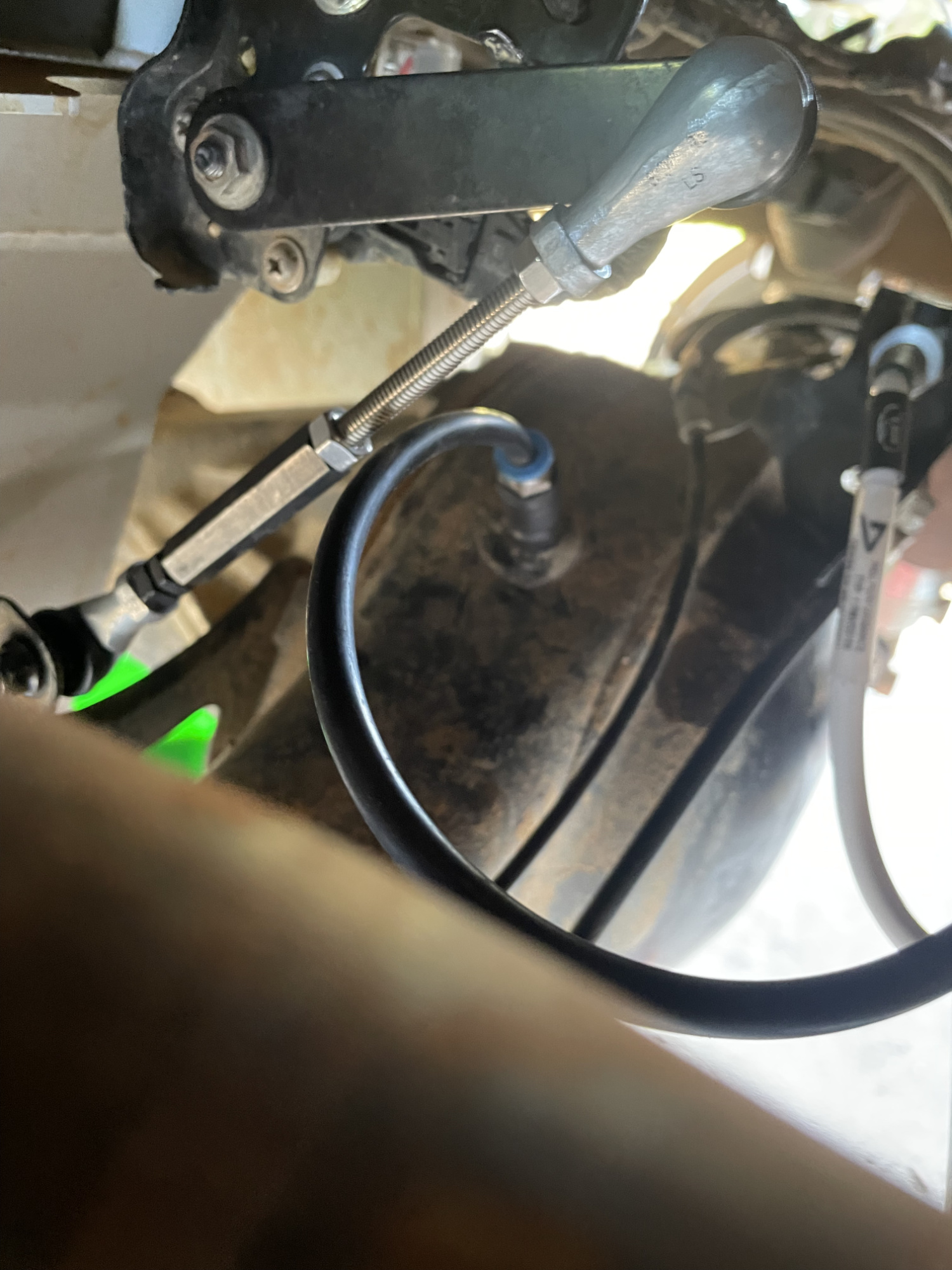
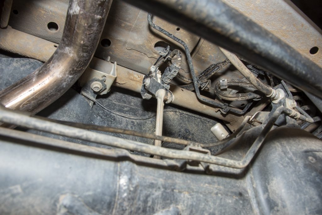
The other thing you need to release before you lower the axle is the various mounts for the brake lines and also the wheel speed sensor wire mount at the top of the diff pumpkin.
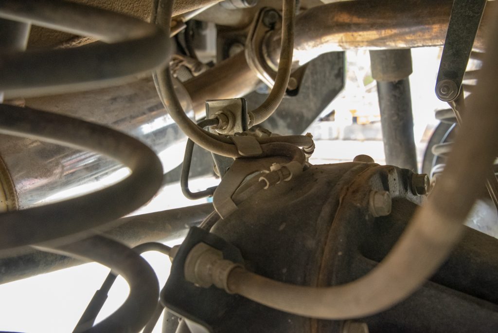
My kit did come with replacement hoses but they seem to be about the same length as standard. I will need to replace them with longer ones as I have rear shock relocation brackets that give more down travel, straining the hoses. In any case, you need the hoses at least unclipped from their mounts so they can move as you lower the axle, as you will over extend the hoses otherwise.
I swapped the hoses at this point to my replacement hoses; because I need longer ones I have left their ‘upper’ mounts unclipped and cable tied them to the chassis out of the way temporarily. Same deal as the fronts: clamp hose, undo bottom flare nut, replace new hose, undo top flare nut, immediately connect to new hose, bleed brakes on each side as you do this.
Now, lightly support the axle from underneath with a jack.
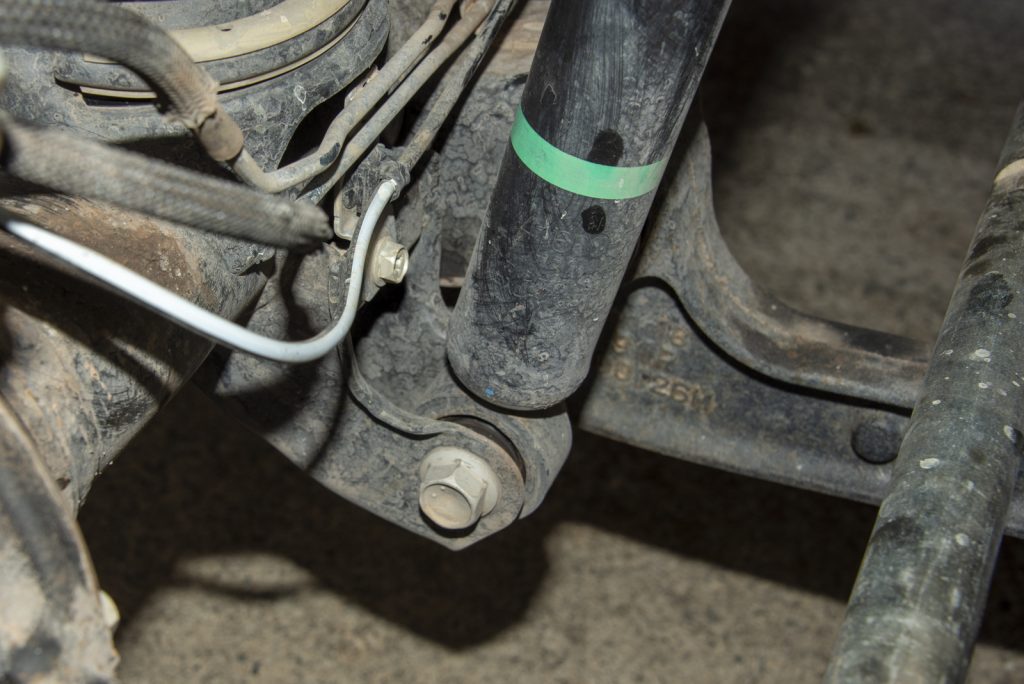
With the axle supported, you’re ready to undo the top and the bottom shock mount bolts and remove the shocks. Upper mount is a 17mm headed bolt which is quite hard to access except using a ratchet spanner on the right-hand side, the left hand side has enough room for a shallow depth socket on a ratchet. Lower bolt is 17mm x2, hold one end with a spanner and the other undo with a ratchet or a big breaker bar.
With the shock removed you can lower the jack and the springs will be released. If you struggle to get the new ones in, you can use the factory Jimny scissor jack between the radius arm and the chassis and it’ll push the axle that little bit lower.
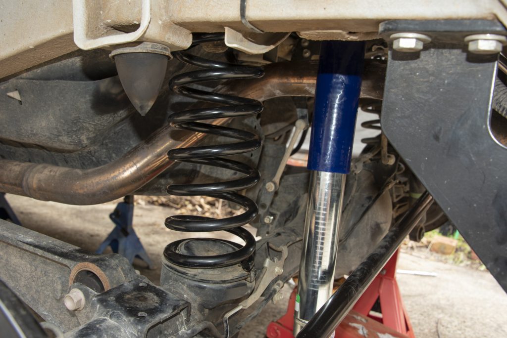
With the springs in, time to throw the shocks in. As I’ve mentioned, I’m running the Black Raptor premium kit so I have adjustable shocks & also I added bottom shock mount relocation brackets. These give a further 40mm of downtravel and reduce the strain on the shocks at full compression as they can pivot.
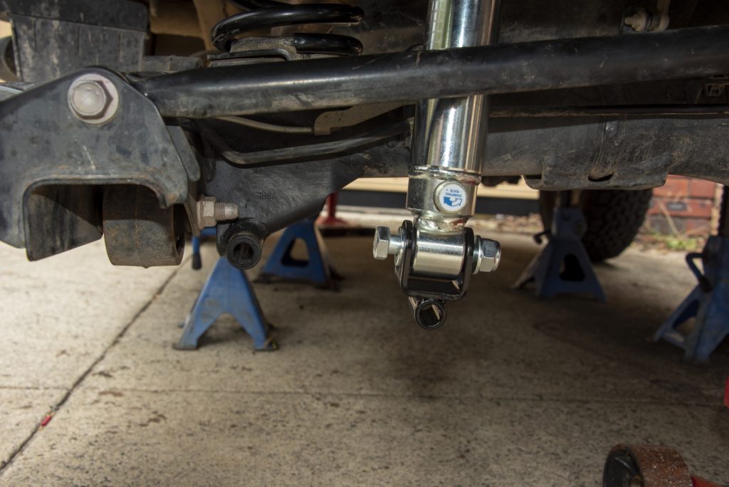
The relocation brackets turn the mount 90 degrees to the regular mount, so you have to mount them up using the supplied bolts and washers. These bolts are 19mm rather than the factory 17mm bolts.
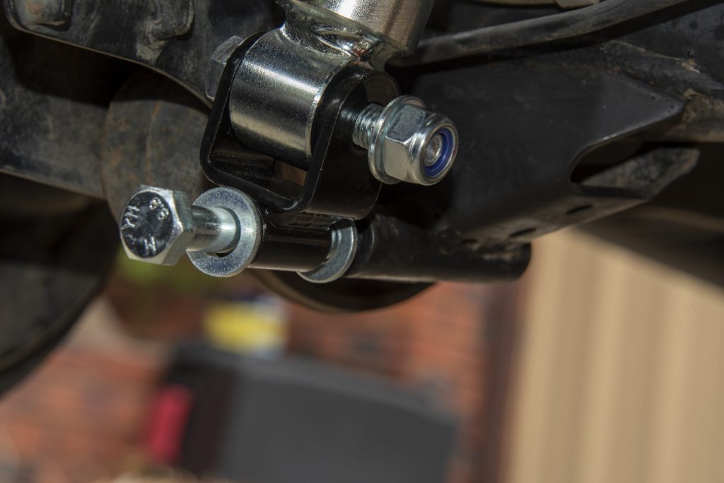
Just like the front, I tighten these up with the suspension taking the weight of the car just in case it makes a difference. Note the top shock bolt is reused, and this has threadlocker applied and is torqued to 70 Nm though getting a torque wrench in to do the right hand side is a challenge. Lower factory bolts are 45 Nm which should be upped to about 60 Nm with the fasteners supplied with the relocation brackets.
Caster correction
There’s two options for caster correction: offset bushes to change the diff angle at the front, or caster corrected arms which achieve the same thing (but can give you greater caster correction).
The first thing to understand is that your need for caster correction depends on two factors:
- Where your car was caster-wise from the factory; and,
- The height of the lift installed.
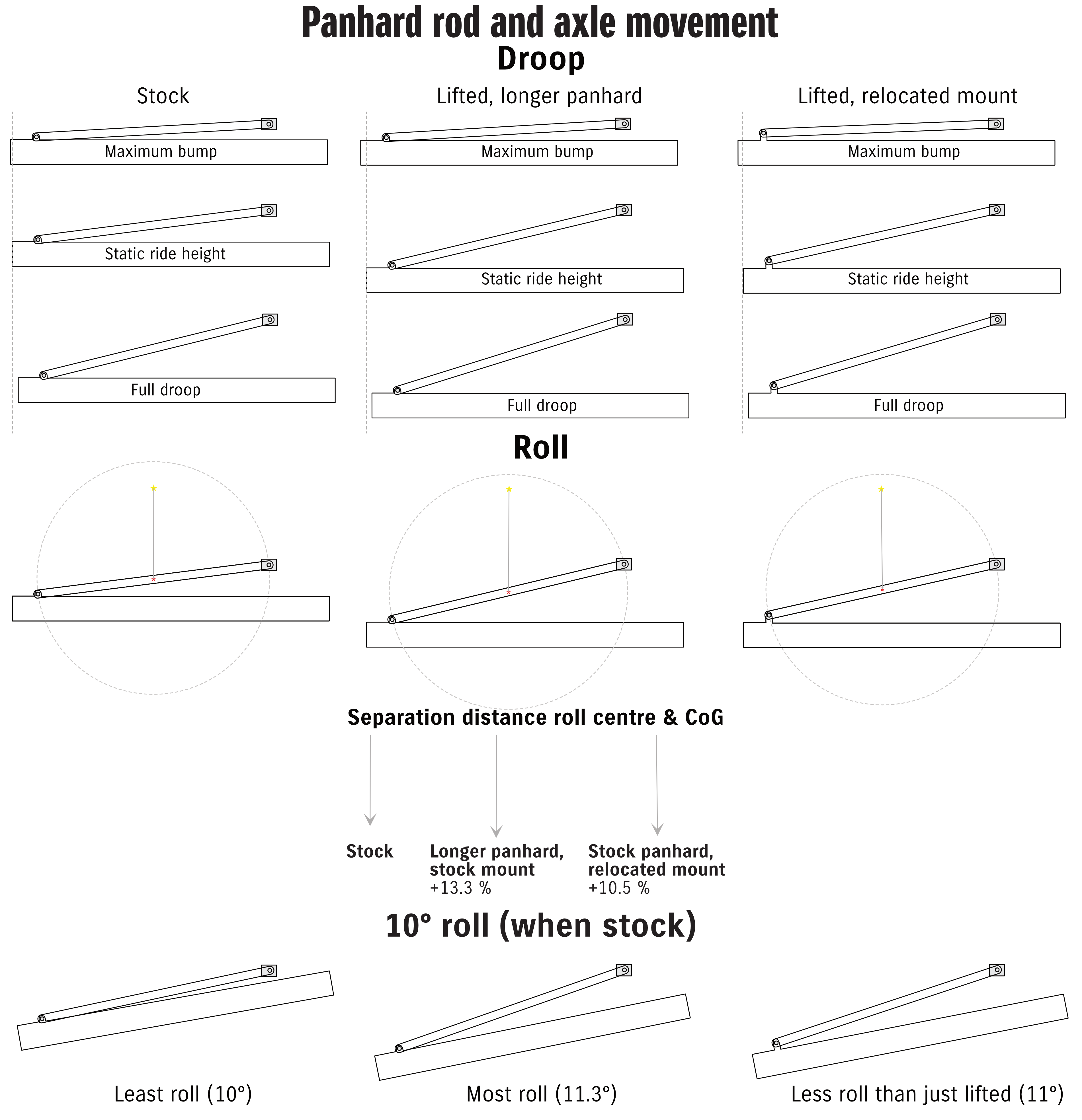
Here’s a figure I drew up for my suspension theory article about the Jimny to help people understand.
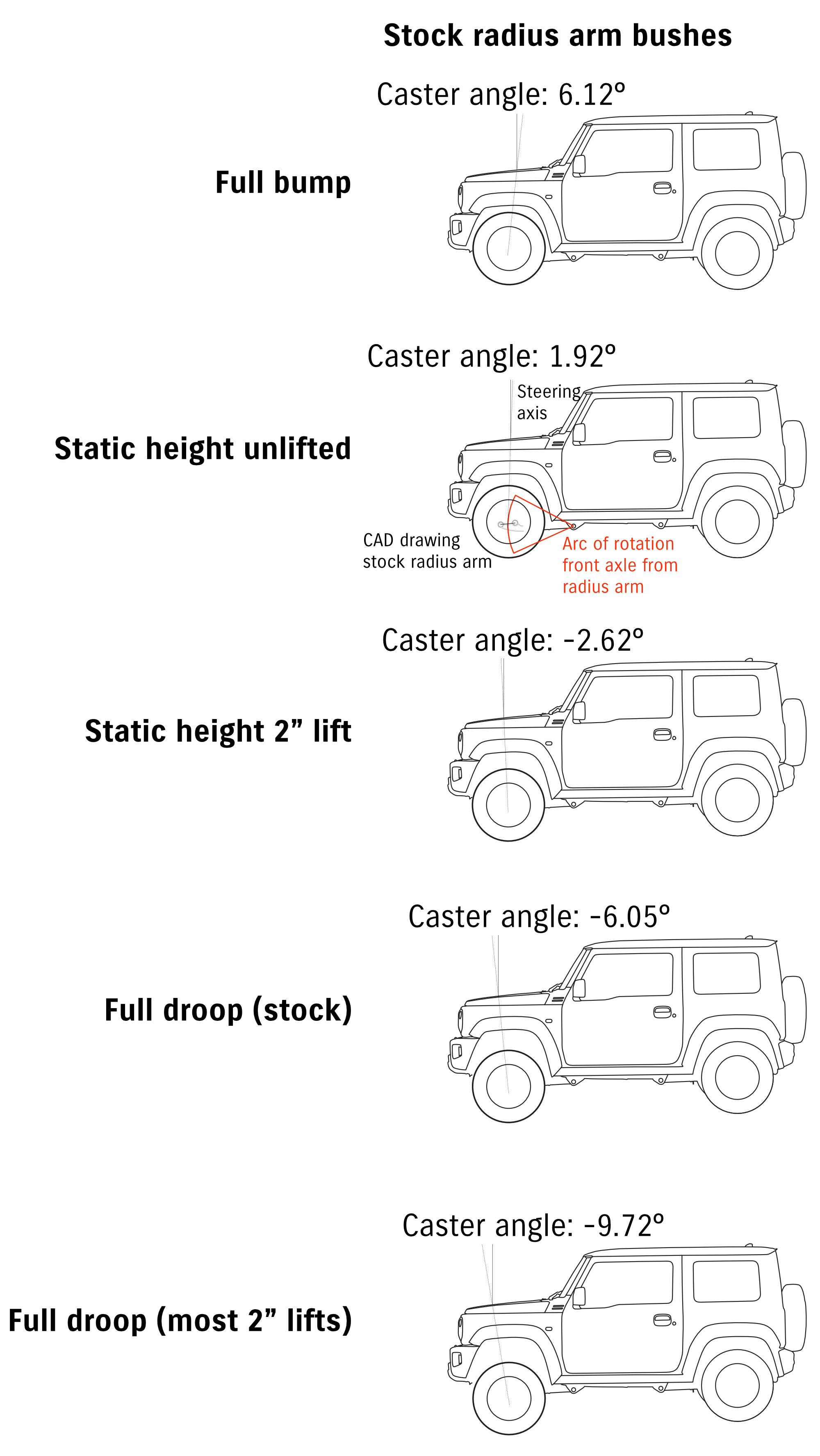
The lift brand doesn’t matter at all, it is entirely down to the lift height. Obviously there’s possibilities where one brand will give you more lift than other despite being advertised at the same nominal height. This will mostly come down to the weight of your accessories on the car and how that changes the height of the lift at the front. The taller the lift the more correction is needed.
The second factor is where the cars are from the factory. The specification on caster is basically ~2º ± 1º. Although it’s not linear, change of -1 to -1.5º per inch of lift is kind of typical. If your car starts off at the upper end of positive caster and you lift it 40mm, you might end up at the marginal end of specification but not excessive. Meanwhile another car, which was already close before lifting, might end up outside of specification for the caster angle with only 20mm of lift. After all, only a small offset in hole position can rotate the diff a considerably amount hence the variability in cars.
You can see this in terms of the Des Sol video on caster correction, where their car was already out of spec with only a limited lift:
There’s no real way to specifically say you *need* caster correction short of measuring the caster after your lift is installed and all settled at an alignment shop (or measuring caster at home). Since almost noone does that as they want the install all done in once then it comes down to personal preference and your own individual circumstances:
- If you’re after a more stable highway performance out of the car, erring on the side of caster correction installation even at 40 mm is worthwhile.
- If you want to save money, and you’re keeping below 2″ for the lift, you can consider skipping caster correction and only adding it if you feel you need it later on.
I ran my car for a couple of years without caster correction, a year with offset bushes in factory arms and also another year and a bit with caster corrected arms. I could drive the car without the caster correction: yes, it was ‘excitable’ on the highway but it was also eager to turn around town and wasn’t something where I felt unsafe. However, other people with lifts the same height as me definitely had less stable cars despite similar setups, so it really does come back also to where you car is: I got lucky, but if you want stability that isn’t defined by luck then you probably want to add caster correction.
Offset bushes
This is the more affordable way to do it, although not necessarily the easiest DIY due to removal of the old bushes and potentially pressing in new ones. If you are going to do this you will either need a press to remove the stock bushes or you need to destroy them to get them out, ideally with an air or electric hammer to help pound them out. New ones are easiest to install if you go for split polybushes, although these have the least flex for offroad use. Non split polybushes can be softer thanks to the protection of their metal outer shell so will flex a bit more offroad.
Note that how you intend to use the car and even the travel of the lift will dictate what to choose when it comes to types of offset bushes. The softer bushes will flex more offroad, which is what you want. Since the axle travels both down and sideways in the suspension stroke, if you have long travel suspension then your radius arms need to accommodate this movement. Soft rubber bushes or pillowball bushes will help more here; rubber ones like Ironman or Dobinsons can work well. Polyurethane bushes can be quite stiff and this will limit your offroad flex more.
Examples of bushes:
- SuperPro polybushes have often been the lifted Jimny option of choice, and have been around forever. SPF5237K is the part number you seek for these.
- Ironman do a factory looking rubber bush (their part number 1146RK) for their 2″ lifts
- Dobinsons also do a semi factory looking rubber bush (WA57-511K) for their 40mm lift kits
- ARB strongly recommend installing their caster correction bushes (OMECA001) for their 40 mm Old Man Emu lift for the Jimny
- Pro Staff bushes have a considerable offset, allowing you to correct large lifts (though the limited amount of material left on the smaller side of the bush might limit their lifespan)
- 4WD PROJECT make a set of 1.5º corrected bushes for smaller lifts e.g. 20mm.
- EFS also do a polybush in a metal shell
- Hardrace offer a hardened rubber bush for 3º or 6º of correction.
No matter the type you install, they are installed with the offsets to rotate the axle to move it forwards to add positive caster to the car. You need to make sure you install them with the correct orientation/offset to do this. While not common, I have seen enough people who have had issues with steering stability where the suspension installer has put the bushes in incorrectly, resulting in the caster being worse than if no caster correction was attempted! Very unideal.
Here’s an example of correctly installed caster bushes from the superpro part listing on JimnyStyle:
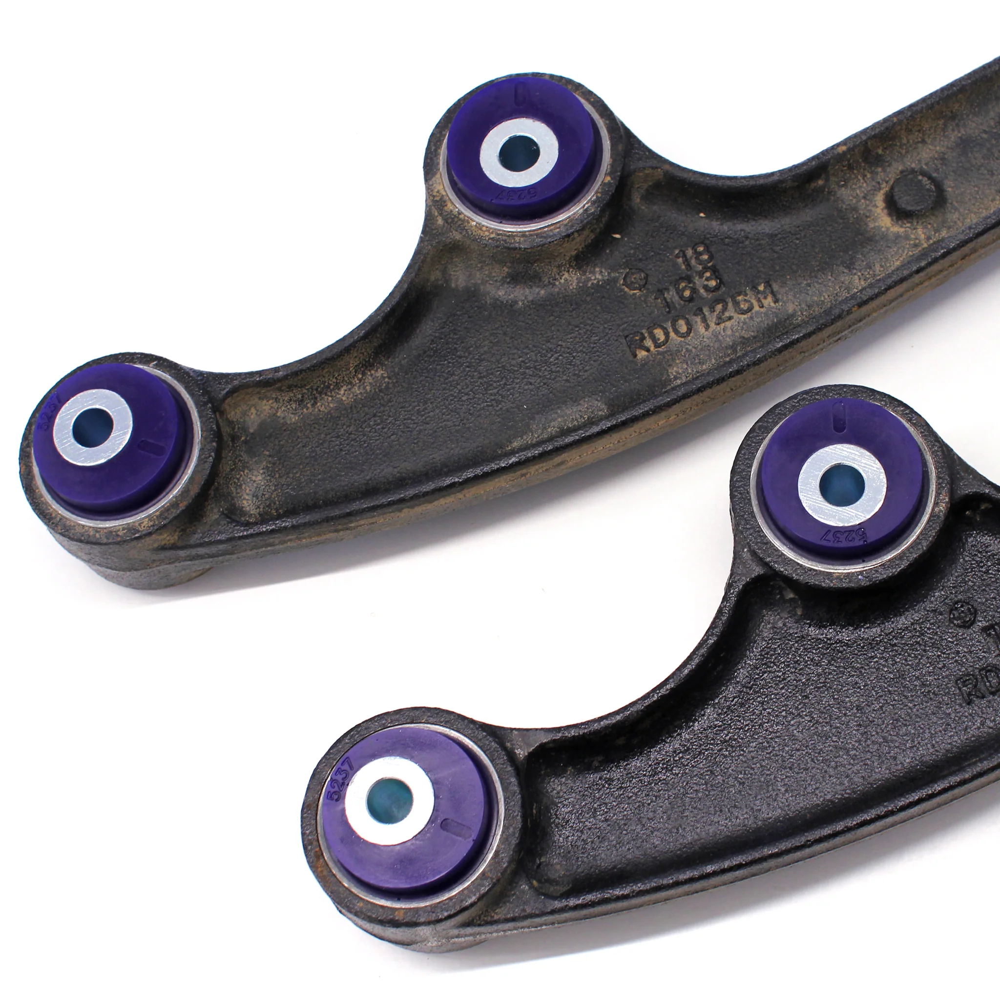
and an example I have illustrated from someone who had steering stability issues after a lift was installed, and this was caused by incorrectly installed offset bushes.
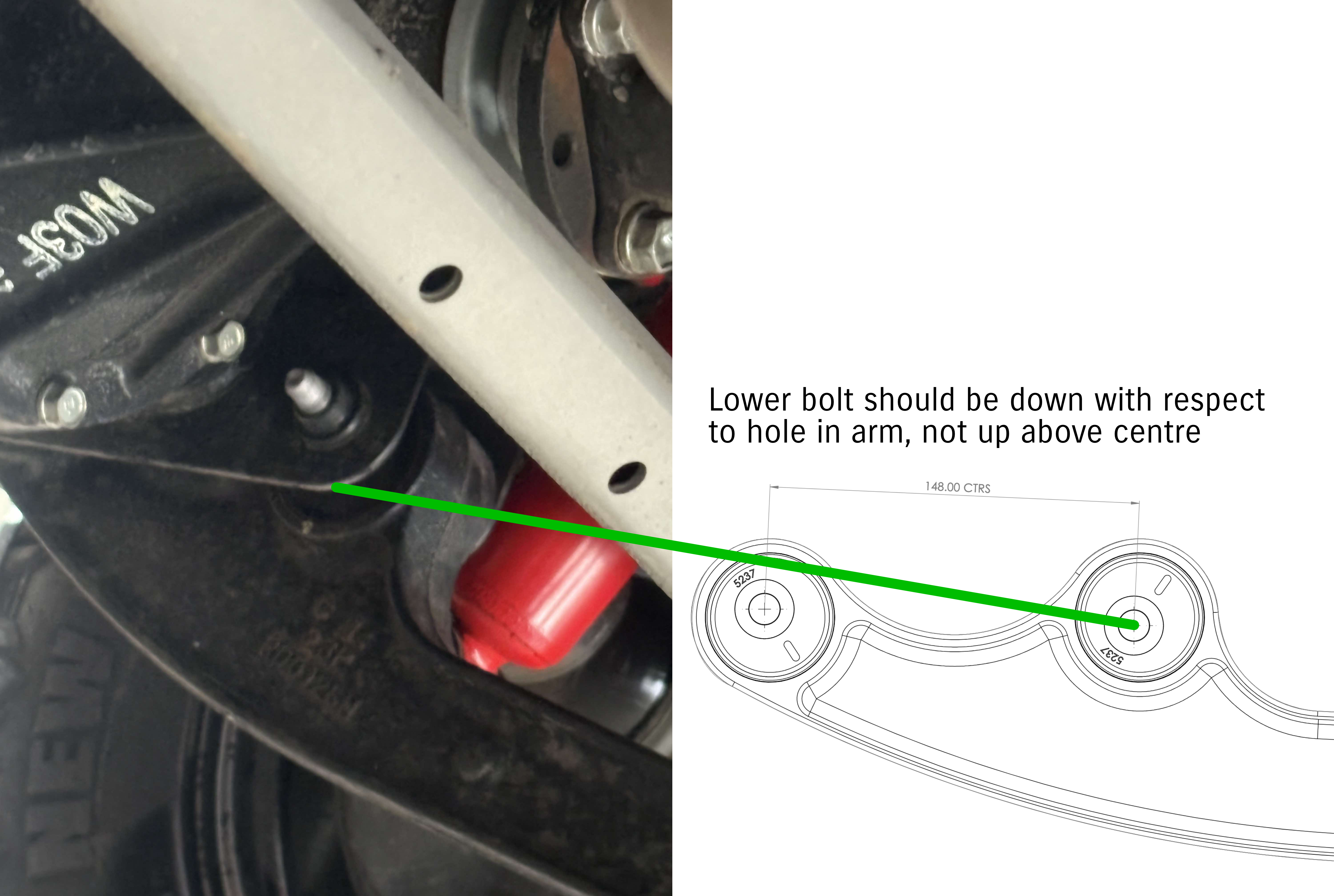
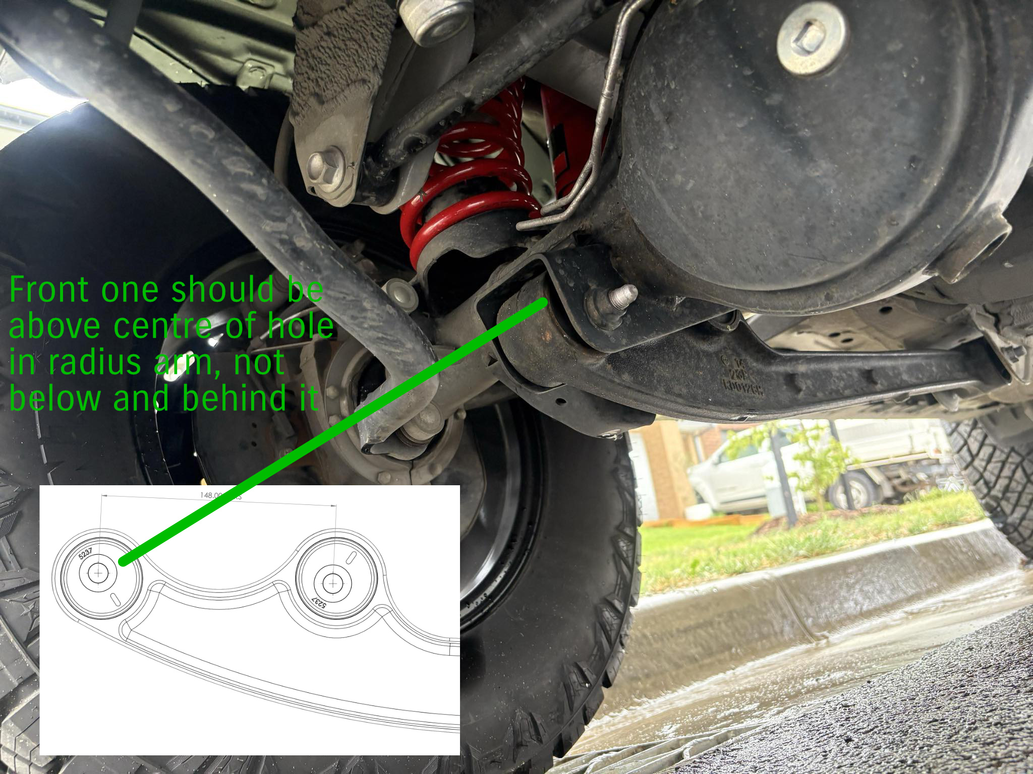
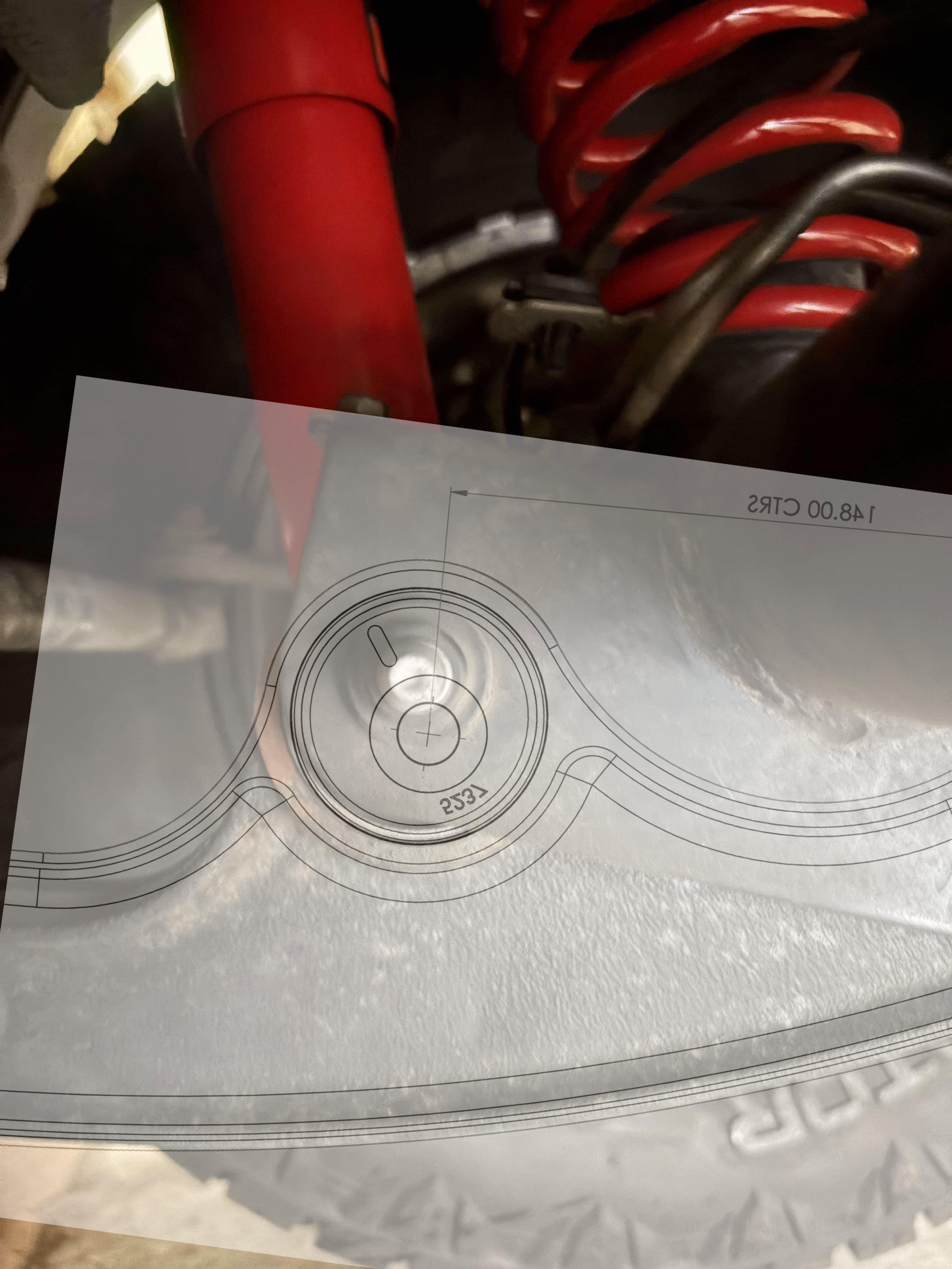
Installation needs to follow the installation instructions or at least think about the rotation of the diff as you install the bushes. Offsets should match what I show here: front one should be above centre on the bush and rear one should be below centre. In the case of bushes like the Pro-staff then you offset one bush and keep the other one stock and again you need to position this offset to rotate the diff to push the axle forwards.
Not every brand has installation instructions or a template out there, but some do:
- SuperPro have the installation PDF linked on their website
- Ironman also provide a template, although their instructions also include marking vertical on the radius arm which will result in caster correction adapted to the car in question
- Dobinsons (via the USA distributor) also provide instructions
Installation is relatively straightforwards; you can remove the radius arms without even lifting the car and in some ways that’s easier as you can use the car to move the diff to line the bolts up once you reinstall. I also like to make up a jig using the stock radius arm bushes to set the distance between the two axle axles at the 148mm they need to be, and also another jig with the distance from one of the two axle bushes to the rearmost bush from the first arm I correct so I guarantee both arms have the same offsets and therefore caster is the same left to right.
You will need to undo the bottom shock bolt because otherwise the shock body gets in the way of removing the rearmost axle to radius arm bolt. Depending on your shock you might get good at pushing it up out of the way to then have it rebound back down… since I run Black Raptor Premium adjustable oil shocks there’s no gas rebound so they stay up and out of the way, so this isn’t a problem for me.
When removing the first arm, loosen off the bolts for the 2nd arm but don’t remove them. This will give you a bit more movement when it comes time to line everything up to reinstall.
With the arm removed, first make up a jig that gives you the bolt spacing between the two axle mount bolts using a piece of wood or something you can jam some bolts through. Mark with an appropriate drill bit, drill and use bolts to make the jig.
With the jig made, press out the factory bush with a press or cut or burn out the middle rubber and punch or destroy the metal shell to get it out.
Clean up the arm, then press in the new bushings noting the orientation using the installation instructions. Once you’re satisfied they’re correct, use the jig to double check the bolt spacing between front and rear axle bolts.
If this is your first arm, make up a jig to set axle to chassing mount bolt spacing too. This will be different to stock (which is how caster correction works, essentially) but you want this to be the same on each side of the car to have equal caster left and right.
To get everything to line up a ratchet strap helps pull the axle backwards if you need it, and you can use the tyre to roll the axle forwards as well. To allow you to rotate the axle, undo the chassis mount end bolt and remove it on the other side to the one you’re fitting. You may need to rock the car back and forwards to get it all to line up nicely and/or use something like a punch or a screwdriver to start lining up bolt holes before running bolts through.
Note that when you have both sides undone from the chassis there can be a lot of movement by the axle, rotating it down which makes it hard to get everything to line up. The key is to get the bolts into the axle housing end of the radius arm first, but just loosely, and then use the radius arms themselves to help line stuff up.
With the arms back in, now you can tighten everything: torque radius arm bolt to chassis to 73 Nm and radius arm to axle bolt/nut to 95 Nm. Lower shock bolt is done up to 60 Nm.
Replacement radius arms installation
This is often the easier option DIY and the more ‘complete option, though you need to carefully select replacement radius arms as some can be weaker or more prone to breaking than standard arms (which usually bend before breaking fully). They are easier DIY as they are a bolt-in option and more foolproof, though some supposedly caster corrected arms for some reason also require you to install offset bushes for full caster correction (I’m looking at you Fulcrum and your Formula 4×4 lift for the Jimny).
I’ve been running Hardrace adjustable arms for a year or so. I don’t necessarily recommend these, but I wanted ways to dial different amounts of caster to understand what the limitations might be e.g. is it bad to run excessive caster or be able to dial the car closer to stock levels with different lifts to see how things change.
I don’t necessarily recommend these for a couple of reasons:
- People have reported them becoming un-adjusted or pulling out with use
- There have been reports of similar arms breaking, especially at the highest stress load point at the rearmost diff mount
I do think if you want caster correction then radius arms are a better route if you are prepared to pay for them. You can get better articulation with them over the stiff offset bushes, and the bushes will last longer since there’s more material around the pin where the mounting bolt goes through.
Removal and installation is the same as for the offset bush installation: shock bottom bolt out, shock out of the way, undo bolts, first arm out, then loosen axle bolts on other side but don’t remove them, and undo and remove the chassis side bolt. Arm installation may require rocking the car or using ratchet straps or a jack to move the axle forwards and backwards to get stuff to line up. It can also help to use a ratchet strap to pull the axle into line if you’re working alone. I usually get the arms installed into the axle for replacement arms and then just move it around with my legs and arms till stuff starts to line up and use punches to get it close to lined up, and then run the bolt in.
Caster correction at the rear?
This sometimes comes up and it’s worth understanding it rather than just snapping back that caster only applies to the front axle. In one sense that is true: caster is a property of steering (forwards-backwards relationship of steering axis to vertical) but there are reasons outside of steering functions to rotate the differential at the rear, too.
Just like the front axle, when you lift the car up the axle housing and hence the differential gets rotated by the radius arms. This means that there becomes an angle difference between the input to the differential and the output of the transfer case. At the front you essentially fix this with caster correction as a byproduct; on the rear with stock radius arms and bushes you don’t have any correction to this differential angle. At large lifts you can get driveline vibrations as the front and rear joints in the driveshaft are no longer equal and opposite: you will have changed the differential angle with the lift, but the transfer case output angle is fixed by the fact it is mounted into the chassis and does not change with suspension lifts.
For moderate lifts, including up to 3″ or so, you probably don’t need to do this, but if you find you have driveshaft vibrations at speed on the highway then you probably can consider doing it. You can use offset bushes and do the same as caster correcting the front or you can fit different rear radius arms to achieve the same effect. Note that driveshaft vibrations are really hard to detect and separate from a wheel balance issue; at best you can spot it because the driveshaft turns about 4x as fast as the wheels do (thanks to the differential gearing). A wheel balance issue will be noticeable every 2m or so of driving, a driveshaft angle every 50 cm or so.
In short: is it necessary to change the rear differential angle, too? No; not for typical Jimny lifts. It might be something you need to consider, or, if you’re doing something more extreme you will probably want to consider it.
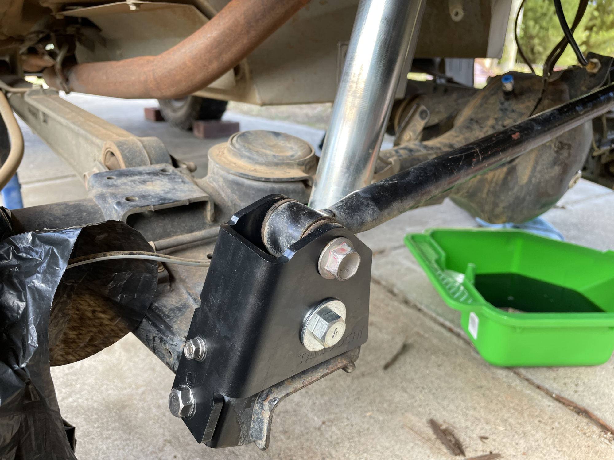
Rear panhard relocation bracket
One element to help with the handling characteristics of the Jimny is to consider the rear panhard relocation bracket. This lifts the axle end of the rear panhard rod up by around 50mm. The main benefit of this is to raise the rear roll centre by half this amount, which counteracts the rear rolling so much with a lift installed. This in turn reduces roll oversteer which is something Jimnys have in spade, so it should help settle the on-road and fast road handling.
There are a number of manufacturers of these brackets, not limited to:
- ARB / Old Man Emu part FK96 (comes with extended rear bump stops but I don’t actually believe they are necessary, since even at full bump there’s a heap of room)
- Taniguchi out of Japan which is what I picked
- Hardrace out of China via their Australian reseller
Sidebar: you need to understand that the relocation bracket is not designed to change the position of the axle at the static ride height of your lift. You offset that with a variable length panhard rod to centre the axles; this is entirely about a handling characteristic.
In addition, some people will notice additional understeer from this modification since the car will naturally oversteer less in cornering. In the 3 doors I think this extra understeer is good, since they are quite tail happy and it does limit their cornering abilities due to reduced stability. Some people have preferred to not run this bracket on 5 doors after testing it; their nearly 40 cm longer wheel base will naturally produce more understeer when cornering anyway.
So I think this is a good addition for a 3 door if you’re after stability, but might not be something you need for a 5 door depending on your desired handling characteristics.
Here’s the factory mount to start with.
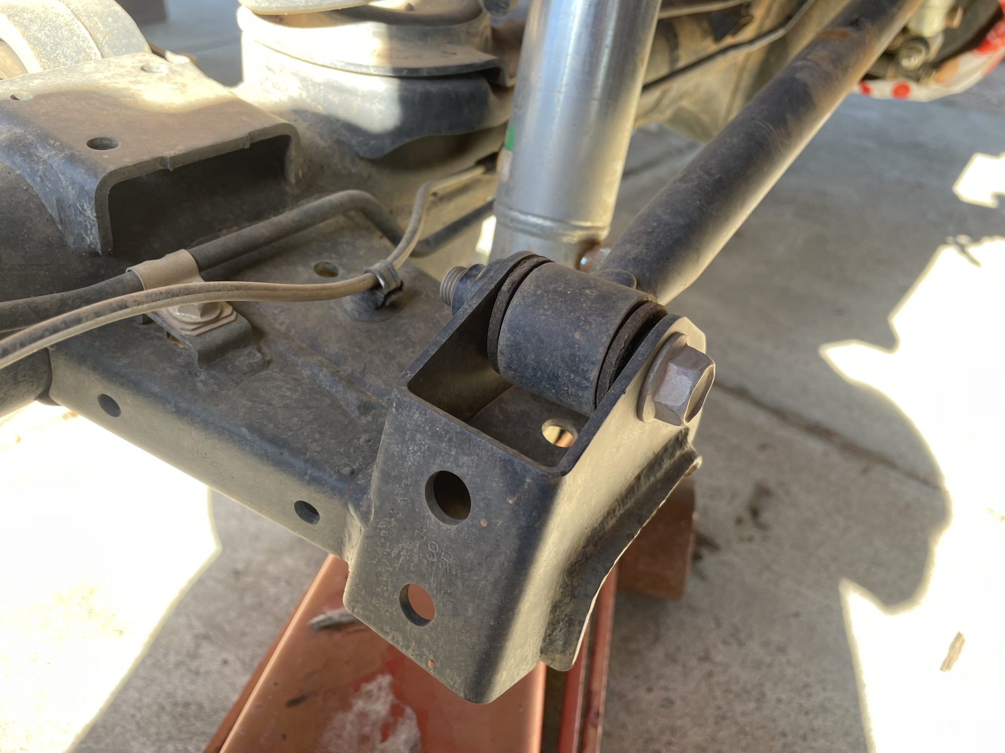
You start by undoing the rear panhard rod bolt at the axle end.
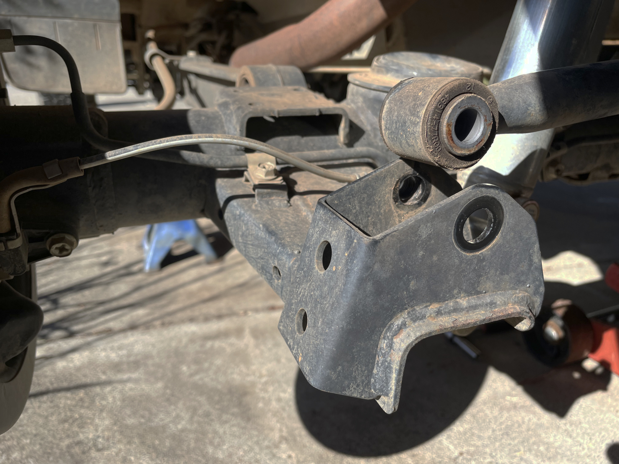
The bracket then bolts on with 3 bolts: a larger one at the bottom, a smaller one at the top, and a bolt that goes through the original mount hole on the axle.
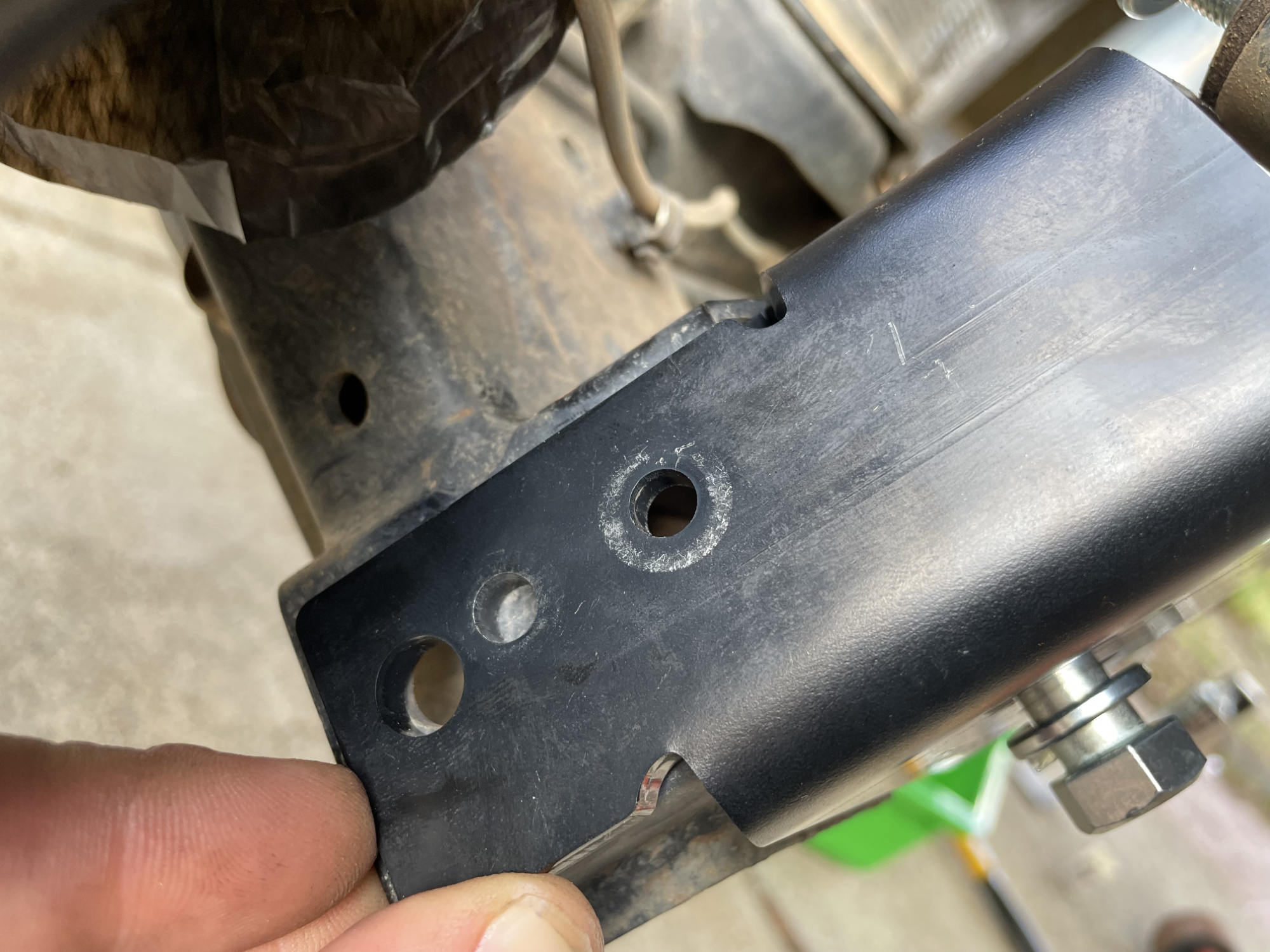
This largest bolt also uses a crush tube to support the bracket.
Install the two back bolts before you put the crush tube in; you’ll need access to get to the nuts for the smallest bolt. Access is hard enough I didn’t get a photo of this step though.
The crush tube is a little hard to get into place with the bracket on the axle housing, but with some gentle persuasion by a hammer it wasn’t too bad to get into place.
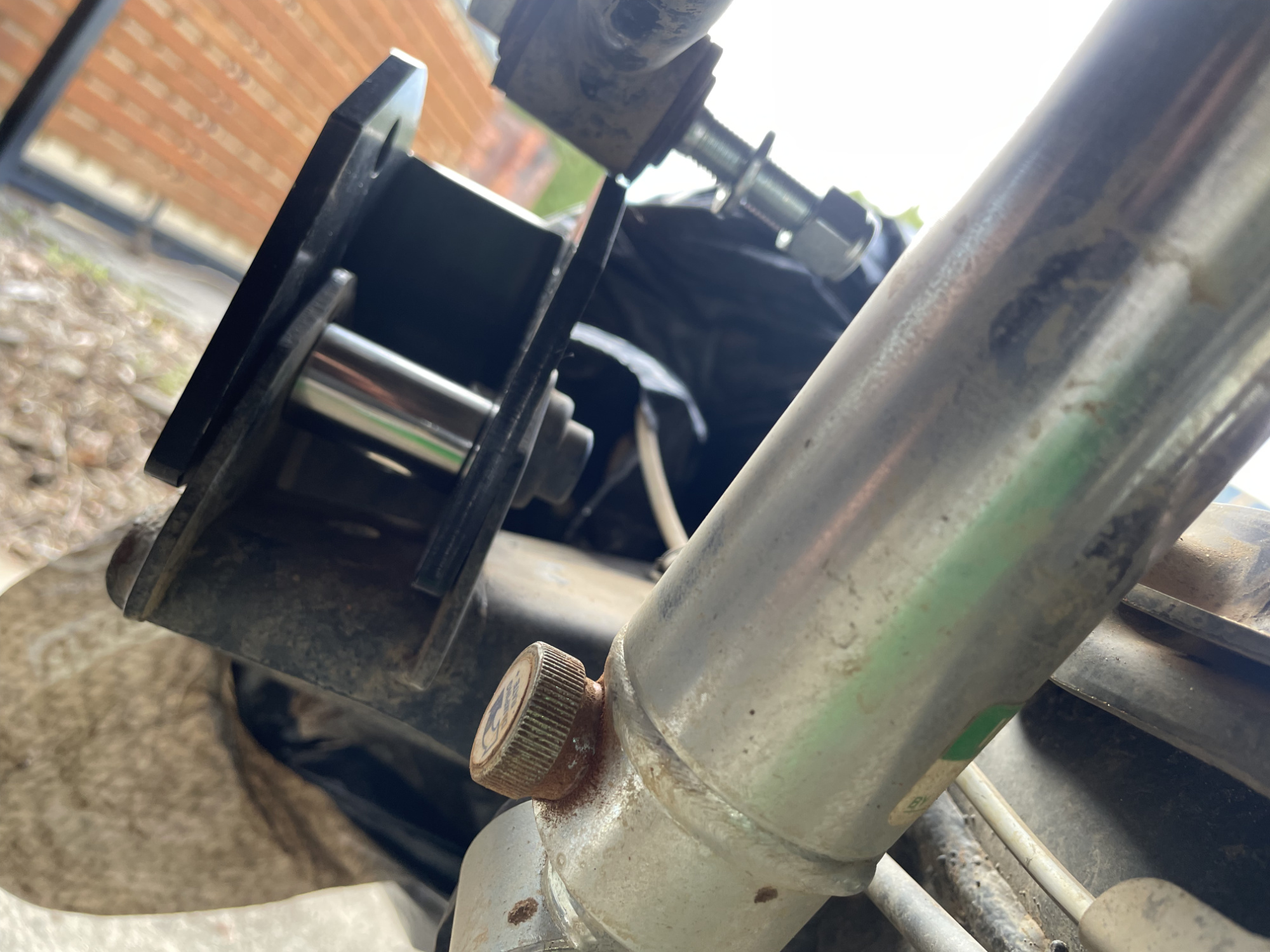
Now you tighten up all of the bolts and install the factory panhard rod bolt in too. You may need to do a bit of wriggling of the axle housing to get it all lined up to get everything to fit.
Tighten everything up to spec and you’re good. Note that you should tighten the panhard rod to the bracket itself with the car at normal ride height. This stops the bush getting a bit bound up. Torque setting for this bolt is 95 Nm.
Extended bump stops
This can be necessary for a couple of reasons:
- If you have desires to run much larger wheels, extending the bump stops is how you make them fit so they don’t interfere with the body at full bump
- If you are running front or rear shock relocation brackets, you gain droop but you can bottom out the shock on bump travel before you hit the bump stops.
Since I am running the ARB bullbar and only 29″ tyres I can get away without extending the front bump stops. If I wanted to run larger tyres or I was using a stock bumper and didn’t want to trim away at the fender liner where it meets the back of the bumper then I would need to extend the front bump stops.
Since I am running relocation brackets on the rear which give me another 38mm of shock length, I did run out of shock travel before I hit the rear bump stops. Fortunately these are easily made up using something to sit on the top of the axles where the rear bump stops land to add a bit of length. There are commercial longer bump stops available but I figured I’d just whip up something.
The best way to check if you need extended bump stops is to pop the springs out with the chassis supported, and then use a floor jack to raise the axle up to maximum suspension travel. If you bottom the shock out before you hit the bump stops, or you hit wheels against bodywork before you hit the bump stops, then it’s bump stop time.
Here’s mine needing about 16 mm of additional bump stop for the 38 mm longer shock relocation brackets I use. Not bad to gain nearly an inch of extra total travel, and this will also ensure there’s less chance of interference of larger tyres into the rear arches.
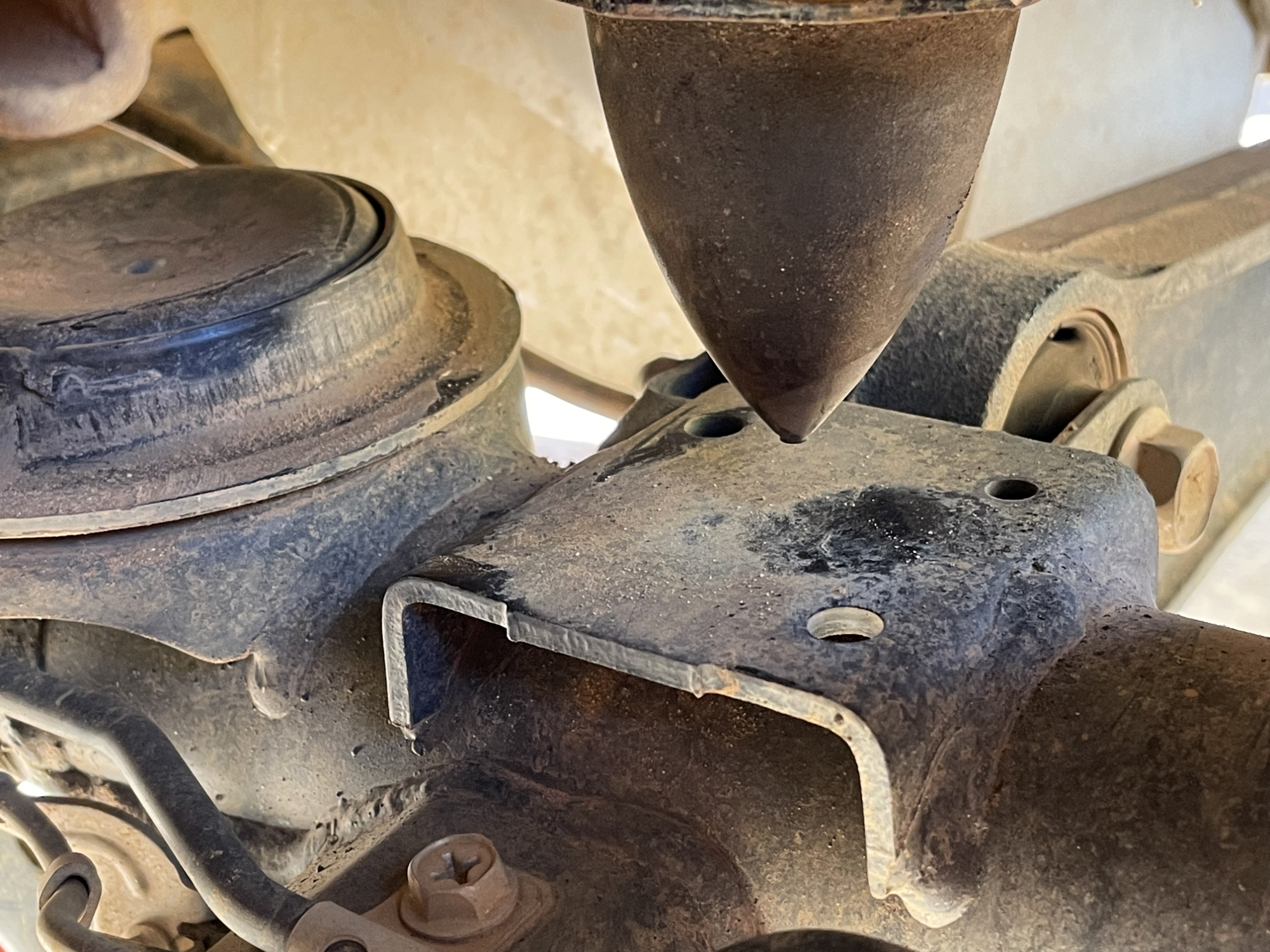
To work out the shape I needed to cut out of some 10mm thick plate I had handy I used a dirty fingertip and a piece of paper to trace out the holes. I then used this to make up a template using a centre punch to give me the hole distances to the 3 existing holes.
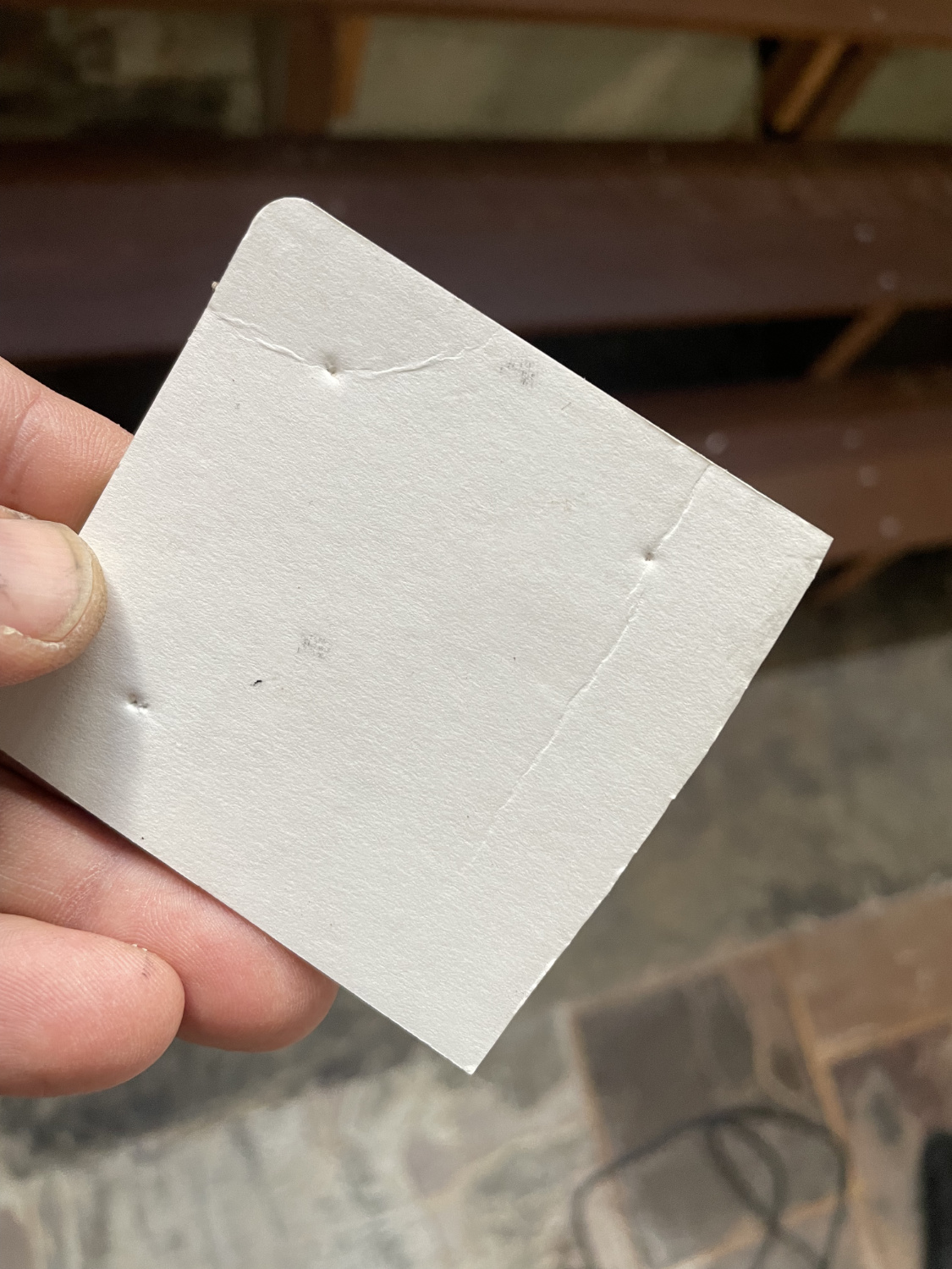
The three holes in the axle aren’t very accessible so I trimmed down some rivnuts so they weren’t too long and installed them after drilling out the holes to 9mm to take M6 rivnuts.
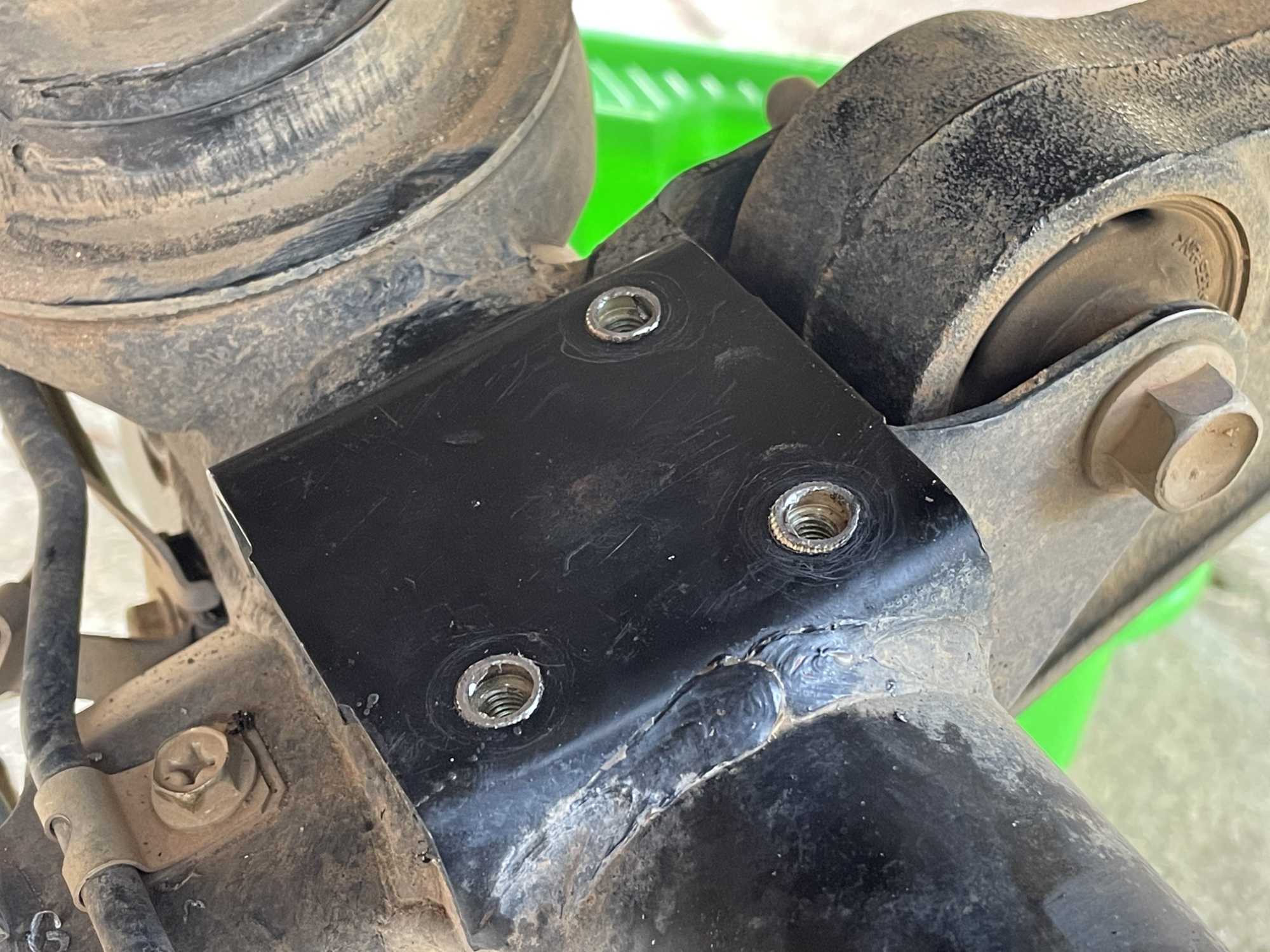
Fairly easy once you cut out and drill whatever you’re using to make up the additional landing pad. I used some old conveyor belt rubber I had and some lightweight plate; I drilled this to match the template and it works great.
Yes, I’m aware there are commercial bump stop extensions available but basically free is always nicer. The fronts would be a bit trickier to do this, but on the rear it’s super easy.
If you do have to replace the front bump stops then you do need to remove the springs. Personally I think if you have the chance then doing this and measuring the required bump stops for your chosen application is the best bet. You can get very conflicted advice on the internet as to how much bump stop is needed for, say, particular tyres; given how much tyre brands can vary in outer diameter you might as well check your suspension travel if you’re going to do it properly.
Steering damper
Unlike some older Jimnys, JB74s come with a steering damper from the factory. In my opinion and experience an aftermarket steering damper is really only useful either a) if you are running exceptionally large/heavy tyres and the steering is not properly returning to centre with the electronic power steering or b) you have stability issues and then they’re only masking a suspension geometry issue. Usually the latter applies, or it relates to used cars bought where there’s other suspension issues (e.g. kingpin bearings are worn enough to make the steering sloppy).
People reading this article for how to do suspension stuff probably aren’t running a 4″ lift using 33-35″ tyres; if you’re in the 2-3″ range and you do caster correction adequate for your lift and what driving characteristics you want you really can make it happy with the stock steering damper.
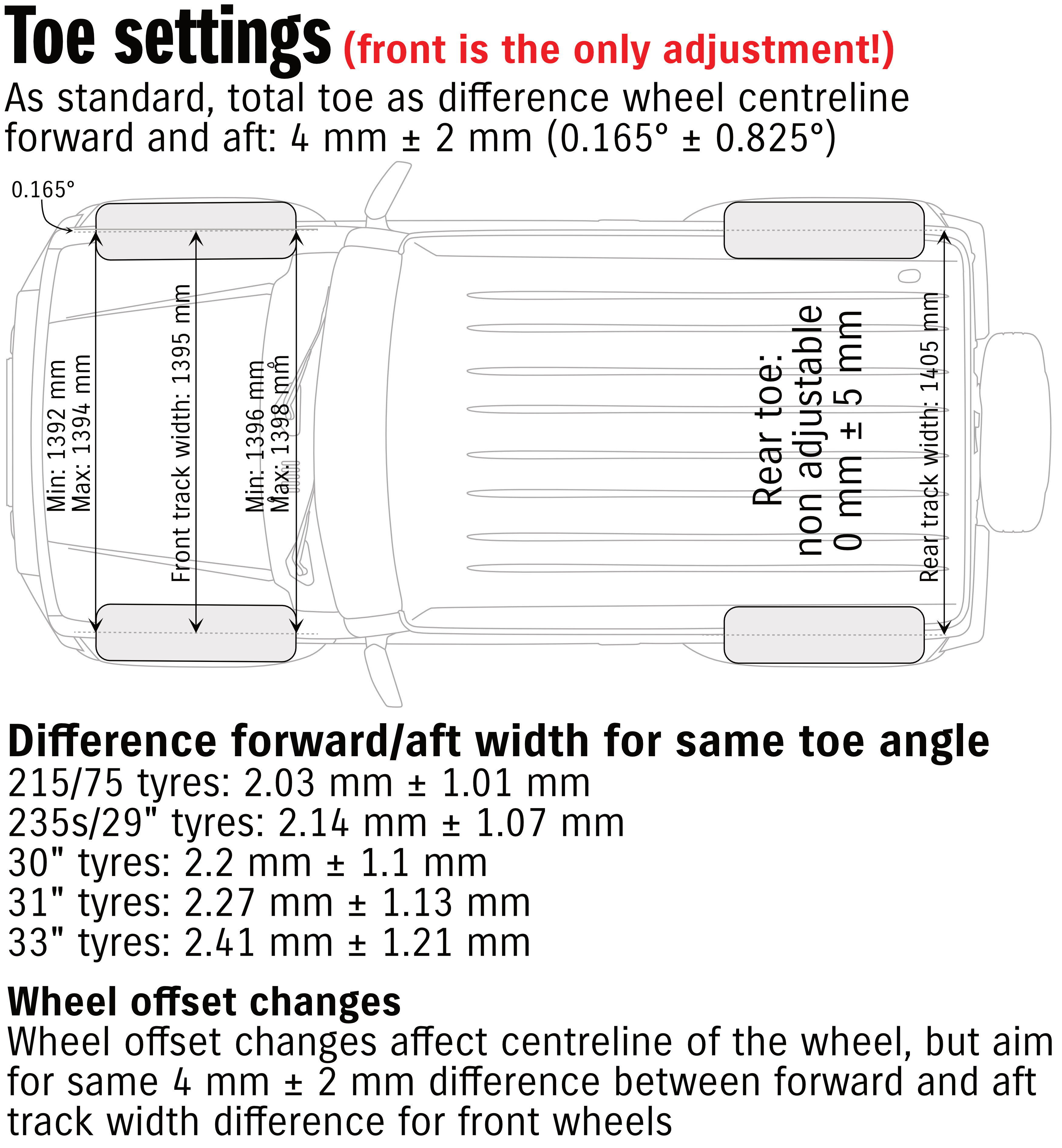
A component of the steering geometry is I’m seeing a lot of alignment charts where places are setting the Jimnys up for 0 mm toe at the front. They should be 4mm total toe measured between front and rear of stock wheels/tyres, and 2mm to 6mm is acceptable. The more toe out you run the more stable the steering will be; so, caster correction and correct toe and you’ll probably find the steering is as stable as you could ever want.
Wheel alignment stuff
The final thing to discuss is wheel alignment stuff. You don’t need a fancy wheel alignment after a lift is installed IF the car already was correctly aligned and you don’t screw with things you shouldn’t be touching when you do the lift. There is only one alignment parameter you can directly adjust from the factory and that is the toe. The toe is set with the toe link between the two front wheels and this is not changed with a lift: it is independent of suspension ride height.
It is possible to screw up this adjustment though and set it up wrong. The toe arm, which is the horizontal threaded rod connecting the two front wheels together at the back of the axle housing, needs to be set up to be sort of spun on or off equally at each end. If you adjust one end and then adjust the drag link you can end up with some weird alignment.
There’s basically nothing else adjustable on a Jimny, so don’t go believing you need a really expensive wheel alignment after doing your lift yourself.
Indeed, pretty much everyone who complains about issues of the car pulling one way or another with the car fighting the electric power steering are people who have used a professional alignment shop. I only know of one case directly where it was a self installed lift; every other example is from a professional alignment shop. In comparison, basically everyone who DIY installs a lift does not complain about the steering angle sensor getting confused after a lift (and it shouldn’t) so I really do think people overthink wheel alignments on a Jimny and then send it to professionals who underthink things and get it wrong.
Drag link adjustment to straight steering wheel
The lift will change what is ‘straight ahead’ for the car, however. When you lift the car the steering box moves away from the wheel that it immediately steers and so you need to lengthen the adjustable drag link to get the wheel pointing straight ahead. You don’t need to adjust the toe angle or anything, just the length of the drag link. This assumes, of course, you had correctly adjusted it.
My car had a slight twist to the right of the steering wheel which was easily corrected just by a tiny change in length of the drag link, but it was already correctly aligned before I did the lift anyway which is why I didn’t have to do a true ‘wheel alignment’.
Checking and setting toe at home
The toe is very easy to set at home, assuming you can rely on your rear axle for setting the toe. The rear track is wider than the front, so you can use the rear tyres to pull stringlines to then check against the wheel rims at the front to get the toe correct.
Checking caster at home with adjustable caster arms
There’s a number of ways to check the caster at home: the official way is to turn a wheel 20º out from the car, measure the camber on that wheel, then turn the wheel 20º inwards and measure the camber again. 1.5x that camber change is the caster measurement.
With the Jimny you have an easier route: the flat of the kingpins are 90º to the steering axis, so measuring the angle of this plate to the horizontal will give you the caster angle. Use a digital angle finder zeroed out to the ground you’re parked on, then measure the angle of the kingpin (either top or bottom will do).
Setting adjustable panhard rods at home
Some people also believe you need a wheel alignment if you are fitting adjustable panhard rods. While a wheel alignment shop will be faster to set centre on the axles, you can verify this by using weights at the ends of stringlines hung down the chassis rails so you can measure distance to the inside lip of the front or back of the wheel rim. If there’s a big discrepancy here then you adjust it to be more centred using an adjustable panhard rod, but a few mm (up to, say, 6mm off centre i.e. 12mm total distance) is probably going to be ok.
Technical stuff
Standard versus lifted height
How much did I lift it? What is standard height, anyway? How much did your bullbar effect it before the lift?
Too many people measure lift just by the height the guards are or similar off the ground. This then fails to take into account
- any replacement wheels/tyres with a different diameter from standard;
- tyre pressure meaning the tyre is squished away from being perfectly round; and,
- the effect of tyre tread wear on the height of the tyre.
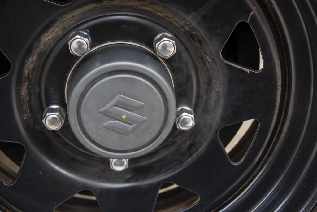
The correct way to measure a suspension or body lift is with respect to the middle of the axle. In lieu of being able to correctly measure this, what I do is make a small mark on the wheel cap in the approx middle of each wheel cap, and then I measure up from the ground to this point and then from this point to the highest point on the guard above the axle.
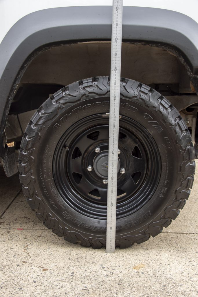
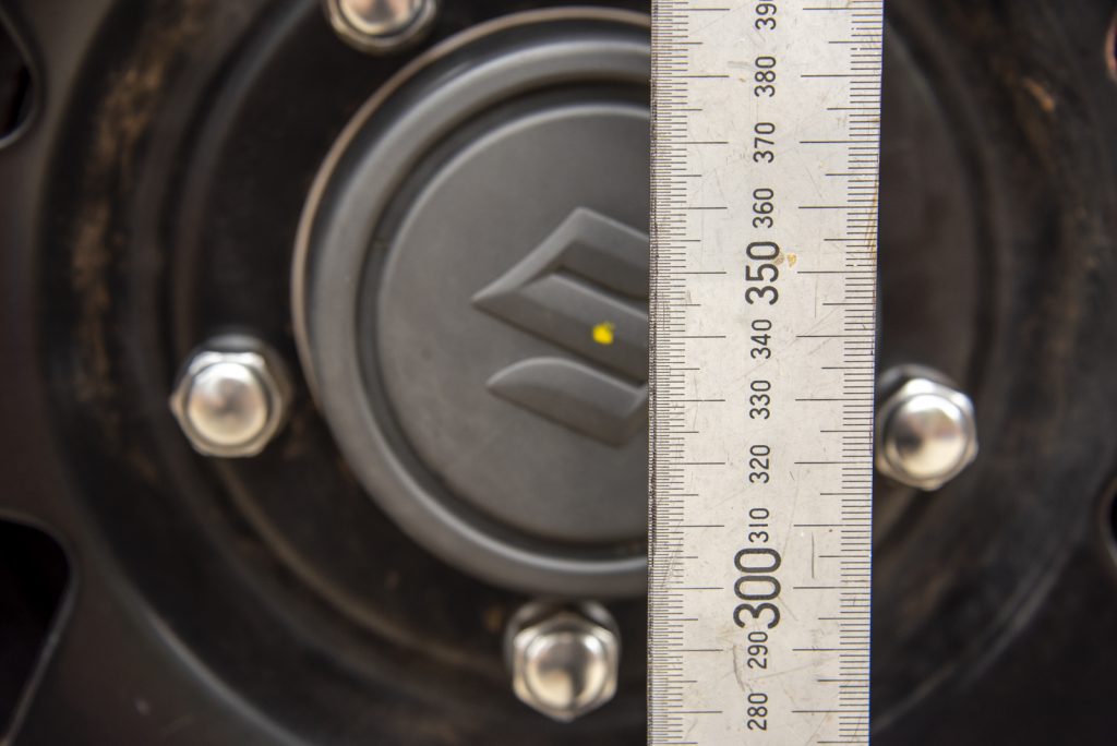
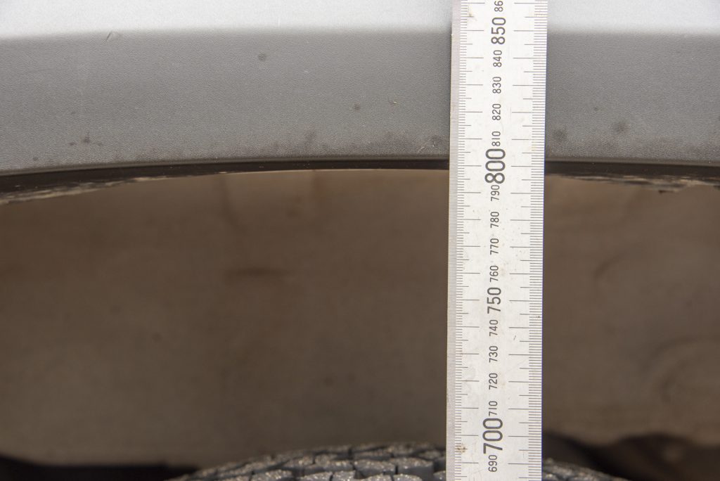
Doing the measurement this way means I can account for different tyre wear etc and also take into account any issue with where I’ve made the mark i.e. if it isn’t centred it won’t matter. The amount you lift is simply how much it changes between this mark and the top of the guard; if your measurements for wheels are different from the ground to the mark for that corner then that’s a sign the mark you have isn’t perfectly centred, but you can take that into account when you do the comparison.
Standard height, according to the vehicle standards information, is 464mm for the front from the centre of the axle, and 479mm at the rear.
Here’s a table with lift measured at various stages, along with standard but with bullbar and towbar added. I’ve added some columns to keep track of it to see if there’s any sag or any difference with adding accessories
| Corner | Standard height (measured centre of axle to guard opening) | Stock 23,000 km, bullbar, towbar, 10L fuel | Lifted: 23k km, barwork, 40L fuel |
|---|---|---|---|
| Front left | 464 mm | 452 mm (-12mm) | 497 mm (+33 specs, +45 from before fitting) |
| Front right | 464 mm | 442 mm (-22 mm) | 492 mm (+28 specs, +50 from before fitting) |
| Rear left | 479 mm | 470 mm (-9 mm) | 509 mm (+40 specs, +49 from before fitting) |
| Rear right | 479 mm | 461 mm (-18 mm) | 506 mm (+27 specs, +45 before fitting) |
The car is much more level and looks like it has about the right rake front to rear. You can also see how much more the drivers side has sagged through just driving with the stock figures, as opposed to the even distribution of the towbar and the bullbar. That said, it still is clearly a little lower on the drivers side which must be some other aspect to it – even down to an uneven driveway where I measured it.
The takeaway from this is the ARB bar does sag it by about 20ish mm and the towbar maybe takes about 8 mm off the ride height. I do plan on fitting spacers to the front once I add a winch, and it looks like maybe 30mm front spacers is a good call to offset the winch and bullbar correctly.
Brake line lengths
Having now had the chance to measure the stock lines, I can report the following lengths. Add length if you need for a lift, and I’ve included fitting information to make it easy to order up custom lines.
| Length | Fitting 1 | Fitting 2 | Support | |
| Front left and right | 550 mm (end of fitting to centre banjo) | M10x1.0 circlip female, straight | M10 banjo bolt, 20º angled | Large circlip fitting x1 |
| Rear long hose | 410 mm (end of fittings) | M10x1.0 circlip female, straight | M10x1.0 circlip female, straight | None |
| Rear short hose | 265 mm (end of fittings) | M10x1.0 circlip female, straight | M10x1.0 circlip female, straight | None |
For my own fittings the specs I used for HEL are the fittings as above, but 61 cm long for the front lines, and 49 cm for the longer rear and 35 cm for the shorter rear.
In addition to the above, I had some back and forth with one of the Aus FB Jimny page members (Chris Dixon) who is doing a setup with minimal lift but long shocks for added droop (~115 mm longer than stock open length). To the lengths I provided Chris suggests the following:
- 90mm longer for the fronts
- 75mm for the rears
This is a lot longer than a typical 2″/50mm lift but that’s what happens with added axle droop!
Spring rates in JB74 lifts
These are now moved over to my article on aftermarket suspension under spring specifications and will no longer be updated here (and removed in a future update to this writeup.
Front
| Lift | Free height | Spring rate | Source |
|---|---|---|---|
| Stock | 350 mm | 22 N/mm | Estimated from spring dimensions |
| OME 3 door no bullbar | 370 mm | 21 N/mm | OME parts catalogue |
| OME 3 door bullbar (part #3144) | 370 mm | 25.5 N/mm | OME parts catalogue |
| OME 3 door bullbar & winch / 5 door no bullbar or just bullbar (part #3145) | 380 mm | 25.5 N/mm | OME parts catalogue |
| OME 5 door bullbar & winch (part #3321) | 395 mm | 28.3 N/mm | OME parts catalogue |
| Tough Dog 40mm (part #TDC1000) | 375 mm | 24.9 N/mm | Estimated from spring dimensions |
| Ironman – variable load (part #SUZ009B) | 372 mm | 27 N/mm | Ironman parts catalogue |
| Ironman – constant load (part #SUZ009C) | 387 mm | 27 N/mm | Ironman parts catalogue |
| Black Raptor 2″ | Drivers: 390mm Passengers: 370mm | Drivers: 19.3 N/mm Passengers: 17.5 N/mm | Guessed from spring marking: 1100 = 110.0 in/lb = 19.3 N/mm 1000 = 100.0 in/lb = 17.5 N/mm |
| Taniguchi 60mm | Drivers: 419mm Passengers: 404 m | 18 N/mm | Taniguchi product listing |
| Showa Garage 50mm | Drivers: 405 mm Passengers: 388 mm | Drivers: 21.95 N/mm Passengers: 22.05 N/mm | Showa Garage product listing |
| Jaos Battle Z lift kit (40mm) | 19.8 N/mm | Jaos JB74 lift kit specification sheet | |
| Pedders TrakRider (part #280150) | 370 mm (loaded 283 mm) | 27.3 N/mm | Pedders product listing |
| Fulcrum Formula 4×4 50mm (KSFR-500 / FCS738, 5 door FCS738X) | 390 mm | 20-21 N/mm | Uses King springs that are unlisted: KSFR-500 Based of spring properties & spring calcuator, measurements by Harrison Steed |
| Dobinsons variable load 40 mm (C57-142) | 385 mm | 25 N/mm | Product catalogue / Dobinsons NZ reseller via Adrian Poole |
| Dobinsons constant load (40-70 kg) 40 mm (C57-110) | 355 mm | 33 N/mm | Product catalogue / Dobinsons NZ reseller via Adrian Poole |
| Raptor 4×4 60 mm | 410 mm | 23.5 N/mm | Jake Mueller FB user measurements |
| King Springs (15-20 mm lift) 3 door: KSFR-63 5 door: KSFR-65 | 3 door: 365 mm | 22.8 N/mm | OzJimny parts listing |
Rear
| Lift | Free height | Spring rate | Source |
|---|---|---|---|
| Stock | Drivers: 315 mm Passengers: 300 mm | 22.2 N/mm | Estimated from spring dimensions |
| OME: medium load (part #3146) | Drivers: 350 mm Passengers: 340 mm | 22 N/mm | OME parts catalogue |
| OME: 100 kg constant load 3 door, medium load 5 door (#3322) | Drivers: 355 mm Passengers: 345 mm | 25 N/mm | OME parts catalogue |
| OME: 200 kg constant load 3 door, 100 kg 5 door (#3323) | Drivers: 375 mm Passengers: 365 mm | 25 N/mm | OME parts catalogue |
| OME: 200 kg constant load 5 door (#3324) | Drivers: 390 mm Passengers: 380 mm | 27.5 N/mm | OME parts catalogue |
| Tough Dog 40mm (part #TDC1003) | Drivers: 340 mm Passengers: 330 mm | 30.9 N/mm | Estimated from spring dimensions |
| Ironman – variable load (part #SUZ010B) | Drivers: 340 mm Passengers: 320 mm | 30.9 N/mm | Ironman parts catalogue |
| Ironman – constant load (part #SUZ010C) | Drivers: 363 mm Passengers: 343 mm | 36 N/mm | Ironman parts catalogue |
| Black Raptor 2″ | 350mm | 26.3 N/mm | Guessed from spring marking: 1500 = 150.0 in/lb = 26.3 N/mm |
| Taniguchi 60mm | Drivers: 376.5 mm Passengers: 362 mm | 23 – 27 N/mm | Taniguchi product listing |
| Showa Garage 50mm | Drivers: 390 mm Passengers: 379 mm | Drivers: 19.6 N/mm Passengers: 19.1 N/mm | Showa Garage product listing |
| Jaos Battle Z lift kit (40mm) | 20.5 N/mm | Jaos JB74 lift kit specification sheet | |
| Pedders TrakRider 50 mm (part #s D/S 280194R, P/S 280194L) | Drivers: 340 mm Passengers: 320 mm | 29.8 N/mm | Pedders info sheet drivers side, passengers side. |
| Fulcrum Formula 4×4 50mm (KSRR-501 / FCS739, FCS739X for 5 door springs) | Drivers: 365 mm Passengers: 345 mm | 27 N/mm | Uses King springs that are unlisted: KSRR-501 Based of spring properties & spring calcuator, measurements by Harrison Steed |
| Dobinsons variable load (0-60 kg) 40 mm (C57-143) | Drivers: 350 mm Passengers: 340 mm | 25 N/mm | Product catalogue / Dobinsons NZ reseller via Adrian Poole |
| Dobinsons constant load (100-200 kg) 40 mm (C57-071) | Drivers: 345 mm Passengers: 333 mm | 34 N/mm | Product catalogue / Dobinsons NZ reseller via Adrian Poole |
| Raptor 4×4 60 mm | 360 mm | 25 N/mm | |
| King Springs 3 door: KSFR-64 (20 mm lift) 5 door: KSFR-66 (15 mm lift) | 3 door Drivers: 330 mm Passengers: 315 mm | 28.9 N/mm | OzJimny product listing |
Note that LHD vehicles for Ironman get part SUZ011B or C which are not staggered (at least according to the catalogue).
Shock lengths
This is also no longer to be updated in this article and will be removed in the future. For details, head over to my aftermarket suspension article in the section on shock specifications.
Front
| Shock | Extended length | Compressed length | Travel | Source |
|---|---|---|---|---|
| Stock Suzuki | 415 mm | 280 mm | 135 mm | Measured |
| Bilstein B6 stock height (part #24-327329) | 401 mm | 266 mm | 135 mm | Bilstein specifications |
| Bilstein B6 raised height (part #24-321730) | 422 mm | 274 mm | 148 mm | Bilstein specifications |
| Bilstein monotube 46 mm (part #BE5 6062) | 402 mm | 285 mm | 117 mm | Bilstein specifications |
| Koni Heavy Track (part #82-2646) | 430 mm | 298 mm | 132 mm | Koni specifications |
| KYB Excel-G front (3430102) | 409 mm | 269 mm | 140 mm | From KYB via FB user |
| OME 40mm (part #60154) | 440 mm | 280 mm | 160 mm | Measured & OME catalogue |
| Tough Dog 40mm | 450 mm | 280 mm | 170 mm | Measured |
| Ironman (part #12759GR) | 440 mm | 277 mm | 163 mm | Ironman catalogue |
| Black Raptor 2″ | ||||
| Taniguchi 60 mm | 475 mm | 297 mm | 178 mm | Product listing |
| Showa Garage 50 mm | 460 mm | 290 mm | 170 mm | Product listing |
| CARBON RR2.0 Remote Reservoir shocks (RR20-JIMNY-19KIT) | 485 mm | 344 mm | Product listing “Long Travel – Open lengths: 19 inch front & 20 inch rear” | |
| Jaos Battle Z lift kit (40mm) | 156 mm | Jaos JB74 lift kit specification sheet | ||
| Pedders TrakRider 50 mm (131098) | No info on product listing but anticipate similar to many other 50mm lifts | |||
| Fulcrum Formula 4×4 50 mm (part 50033) | 452 mm | 277 mm | 175 mm | Thanks to Harrison Steed for the info |
| Dobinsons nitro-gas standard (GS57-615) | 398 mm | 273 mm | 125 mm | Product listing on 3rd party site: lengths might not be comparable, travel calculated |
| Dobinsons nitro-gas 40 mm (GS57-617) | 438 mm | 283 mm | 155 mm | Product listing on 3rd party site: lengths might not be comparable, travel calculated |
| Dobinsons IMS 40 mm (IMS57-50617) | 460 mm | 305 mm | 155 mm | Measured by user in Aus FB group |
| Dobinsons IMS 75 mm (IMS57-50613) | 465 mm | 311 mm | 154 mm | Product catalogue |
| Dobinsons IMS remote reservoir 3″ | 460 mm | 305 mm | 155 mm | Measured by user in Aus FB group |
| Raptor 4×4 60mm | 470 mm | 300 mm | 170 mm | Jake Mueller measurements Aus FB user |
Rear
| Shock | Extended length | Compressed length | Travel | Source |
|---|---|---|---|---|
| Stock Suzuki | 450 mm | 305 mm | 145 mm | Measured |
| Bilstein B6 stock height (part #24-327336) | 454 mm | 298 mm | 156 mm | Bilstein specifications |
| Bilstein B6 raised height (part #24-321747) | 477 mm | 320 mm | 157 mm | Bilstein specifications |
| Bilstein monotube 46 mm (part #BE5 6063) | 453 mm | 303 mm | 150 mm | Bilstein specifications |
| Koni Heavy Track (part #82-2647) | 461 mm | 320 mm | 141 mm | Koni specifications |
| KYB Excel-G (3430100) | 451 mm | 302 mm | 149 mm | From KYB via FB user |
| OME 40 mm (part #60155) | 515 mm | 325 mm | 190 mm | Measured & OME catalogue |
| Tough Dog 40 mm | 510 mm | 340 mm | 170 mm | Measured |
| Ironman (part #12760GR) | 495 mm | 310 mm | 185 mm | Ironman catalogue |
| Black Raptor 2″ | | | | |
| Taniguchi 60 mm | 525 mm | 331 mm | 194 mm | Product listing |
| Showa Garage 50 mm | 515 mm | 327 mm | 184 mm | Product listing |
| CARBON RR2.0 Remote Reservoir shocks (RR20-JIMNY-19KIT) | 510 mm | 354 mm | | Product listing “Long Travel – Open lengths: 19 inch front & 20 inch rear” |
| Jaos Battle Z lift kit (40mm) | 176 mm | Jaos JB74 lift kit specification sheet | ||
| Pedders TrakRider (131099) | No info on product listing | |||
| Fulcrum Formula 4×4 50mm (part 50034) | 533 mm | 330 mm | 203 mm | Thanks to Harrison Steed for the info |
| Dobinsons nitro-gas standard length (GS57-616) | 460 mm | 310 mm | 150 mm | Product listing on 3rd party website: lengths might not be comparable to others; travel is consistent though |
| Dobinsons nitro-gas 40 mm (GS57-618) | 495 mm | 323 mm | 172 mm | Product listing on 3rd party website: lengths might not be comparable to others; travel is consistent though |
| Dobinsons IMS 40 mm (IMS57-50618) | 505 mm | Measured by user in Aus FB group; previous measurements were from a 3rd party site (560 mm; 420 mm; 140 mm) | ||
| Dobinsons IMS 75 mm (IMS57-50614) | 531 mm | 353 mm | 178 mm | Cheers to the person providing background info on them |
| Dobinsons remote res 3″ | 530 mm | 345 mm | 185 mm | Measured by user in Aus FB group |
| Raptor 4×4 60 mm | 505 mm | 330 mm | 175 mm | Jake Mueller Aus FB member measurements |