
Jimny alternators: issues, changing them, tearing one down
Every year that winter comes around and people go play in the mud with their Jimnys you get, usually a week or two later, a raft of people wanting to know why their charge light is on and their car isn’t working right.
Jimny alternator details
The Jimny’s factory alternator is a Denso unit, part number 31400-81P00. These are a 90 A unit, and are controlled over LIN for variable charging abilities. This alternator is shared with cars with the K12C engine such as the Ignis, Baleno and Swift from about 2015 onwards (depends on the car). These cars can be a good source for used alternators and much cheaper than the parts individually.
Speaking of parts, here’s the breakdown
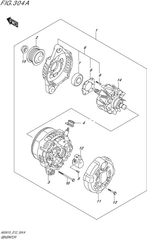
| Figure label | Part number | Description |
|---|---|---|
| 1 | 31400-81P00 | Entire alternator assembly |
| 2 | 31171-81P00 | Pulley |
| 3 | 31401-81P00 | Stator assembly/rear case |
| 4 | 31514-61P20 | Terminal bushing |
| 5 | 31516-85250 | Brush holder screw (x3: torque to 2.0 Nm) |
| 6 | 31580-81P00 | Front case/bearing/retaining plate assembly |
| 7 | 31580-81P00 | Front bearing |
| 8 | 31585B82111N000 | Front bearing retainer plate |
| 9 | 31586-73J00 | Front bearing retainer screw (x4: torque to 2.3 Nm) |
| 10 | 31587-72M00 | Frame bolts (x4: torque to 6 Nm) |
| 11 | 31614-74P00 | Brush holder plastic cover |
| 12 | 31656-61J20 | Brush holder assembly |
| 13 | 31692-77M00 | End cover bolt (x3: torque to 4.5 Nm) |
| 14 | 31710-81P00 | Rotor assembly and rear bearing |
| 15 | 31775B86510N000 | Pulley nut (torque to 130 Nm, holding rotor shaft with 6 point 10 mm socket) |
Note that the rectifier is integral to the rear frame/stator assembly (part #3 in the parts breakdown). If you have a failure of the rectifier then you need to replace at least this assembly, though practically it’s easier to replace the entire assembly.
Issues
There’s not really any huge issue with the alternators; like most 4wds they are a little vulnerable to mud and dirt as the engine bay isn’t sealed, and the small 4 cylinder engine means there’s a bit of room for stuff to get around them. Jimnys are not the only vehicle with alternator failures from mud ingress, and, as much as you might think a 4wd should be indestructible and therefore not suffer from this, short of fitting a water cooled alternator then all alternators are open to the elements and risk such issues. Larger 4wds often don’t end up with these issues not because of better design but often the owners have some 4wd experience and have already killed some alternators when they started out 4wding and now avoid mud or clean the alternators out.
There appear to be two main failure modes with mud/water ingress. The first is physically stopping the brushes contacting the rotor through mud holding them back or wearing them down completely to past their servicing limits. The other failure mode potentially relates to washing the alternators with high pressure water OR from significant water ingress and has water get into the bearing(s) in the alternator. If it’s the front bearing then you can replace it having taken the alternator apart, but if it is the rear bearing then you need to replace the entire rotor assembly as the bearing is pressed onto the shaft and not removable. (Potentially you could cut it off and replace it with a new bearing, but likely you will damage the rotor doing so).
To avoid such issues there are a few solutions:
- Don’t play in mud. This isn’t an option for most people.
- Clean the alternator out after playing in the mud.
This won’t solve everything and be careful about not spraying it hard with water. Using gentle water with the engine running appears to be the best.
There are a couple of areas that could be repaired on the side of the road with alternator failures. While you won’t be replacing bearings, you can pull the back end cap off the alternator and clean out the brushes and make sure the contact there is pretty good. To do this you don’t even need to fully pull the alternator apart, and it might be enough to get you home in a pinch. See the teardown later on in the page for how you might do this.
Related to these issues is that the idler pulley can also develop issues from water ingress, again not unique to the Jimny. If this pulley siezes then it’ll usually snap the alternator belt and then your car won’t be charging anyway. Idler pulley is part number 17530-50M00, waterpump belt 17521-78R00 (5PK951; can use 5PK950 in a generic multi-rib belt).
Smart alternator details
There is an additional potential issue in that these are smart alternators. You need to be careful about how you hook up a 2nd battery to make sure it both doesn’t drain the main battery when parked and you also need to think about how you connect up any earths so they go through the current sensor. I’ve covered a way to do that if you need to increase the earth wiring capacity elsewhere.
The ECU uses a number of inputs to make a decision on what to request of the alternator. It monitors:
- Battery voltage (via ECU power supply voltage)
- Throttle position, coolant temperature, engine speed and road speed
- Load from inputs from BCM (e.g. blower fan on maximum, headlights on, rear demister on)
- Load from electrical current sensor on negative terminal of battery
- Battery temperature from sensor on negative terminal of battery
The alternator operates by adjusting the voltage regulator via LIN to vary its output voltage according to these inputs. If the electrical load sensor is not detected correctly, the car doesn’t automatically go to full charge but instead operates by the other input parameters.
The alternator with no electrical loads present (i.e. the BCM not reporting particular electrical loads) will still produce 10 A excess current at idle with a battery that isn’t fully charged. At 2000 rpm engine speed with the headlights on, rear window demister and maximum speed on the A/C fan the alternator will produce up to 20 A current to charge the battery.
Output voltage specified of the regulator is 10.6 – 16.3 V.
How to change an alternator
I’ll get pics of this one day but writing up the details now so if anyone needs to change one then a text how-to with torque values should help.
Removal
First step is to isolate the car’s electrical system by removing the negative battery cable. The main alternator power cable is connected to the positive terminal, without isolating the electrical system you risk shorting out the battery directly to the engine block which is a great way to learn spanners can weld themselves to parts of the engine using DC electricity.
After removing the negative battery terminal, take off the hose that runs between the side of the car and the airbox. This will help with access.
After doing this you should have enough room to undo the nut that connects the main battery cable to the alternator. Undo this nut and remove the cable off the alternator.
Unclip the LIN communication plug off the back of the alternator.
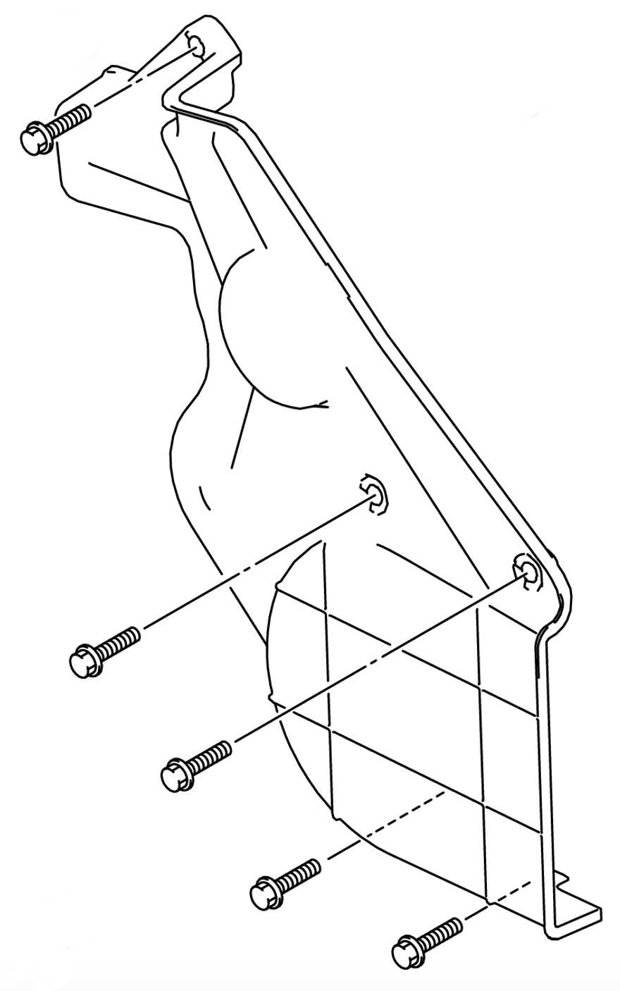
The next step is to remove the waterpump/alternator belt cover. There are 5 bolts here: one at the top, 2 in the middle to the middle of the engine, and two at the bottom of the cover (again towards the middle of the engine).
With those bolts and cover removed, loosen the bottom and top bolts on the alternator (but don’t fully remove them).
You can then loosen the adjuster bolt, slackening the belt that drives both the waterpump and the alternator.
Now you can flick the belt off the alternator pulley. If you aren’t changing the belt then you can just leave it on the rest of the pulleys; if you are removing it you need to remove the A/C belt first which is a stretch belt and removed using a belt removal tool (and I’ll cover how to do that elsewhere).
With the belt off the alternator’s pulley and all the cables removed, start by removing the top alternator bolt which will let you pivot the alternator fully away from the engine…
…and now remove the bottom alternator bolt, supporting the alternator with your hand.
Remove the alternator from the engine bay.
Measure the distance between the alternator support bushing on your old alternator and the front of the frame. This is to help make it easier when you go to put the new alternator on.
Get your new alternator and measure the distance between the support bushing at the back and the front of the alternator.
If this gap is smaller than the gap on the alternator you just removed then you need to push the bushing back. Use a socket, a bolt and a washer as a bushing puller and you can pull the bushing backwards slightly to gain clearance.
Refitting
First start by putting the alternator in place and putting in the bottom bolt.
Tighten this bottom bolt to 30 Nm which should pull the bushing against the alternator bracket. There should be no clearance here between the bushing and the bracket.
Loosen the bottom bolt again but don’t remove it, just have it just off starting to get finger tight.
Push the alternator up and tighten up the top bolt against the adjuster mechanism.
With the adjuster fully loosened, pull the belt over the alternator. If you struggle with a new belt where it can be quite tight you can do this as you fit the alternator bolts instead of doing it separately.
Tension the belt so you get about 7-8 mm of deflection halfway between the waterpump and the crank pulley. A new belt will have about 5-6 mm of deflection as it won’t have stretched quite as much.
With the belt tensioned you can now fully tighten the two main alternator bolts:
Alternator top bolt: 25 Nm
Alternator bottom bolt: 48 Nm
The tensioner is also torqued to 5 Nm, but this should be covered just by the belt being in tension.
Refit the belt cover and its 5 bolts. All 5 bolts should be equal lengths (M6 x 25 mm bolts) and are torqued to 11 Nm.
Refit the LIN communication cable to the alternator.
Refit the main battery cable to the alternator and tighten down its nut (torque setting: 8 Nm).
Airbox hose now goes back onto the car.
To wrap up, finally you’ll reconnect battery negative to the car and you’ll be ready to start the car with your new or repaired alternator installed.
After changing
After changing the alternator, you might have check engine lights and/or a bunch of pending codes in your various modules around the car. Usually these will reset themselves after a few starts, but some can be persistent as they relate to safety modules.
The best suggestion here is to use something like szviewer and scan all of the modules, write down the error codes and then reset all the codes in all of the modules. Here is an example from a recent issue where someone’s alternator died and they drove as far as they could to help get it somewhere. The car died from lack of voltage and these are some of the codes stored in the modules which triggered a check engine light upon restart.
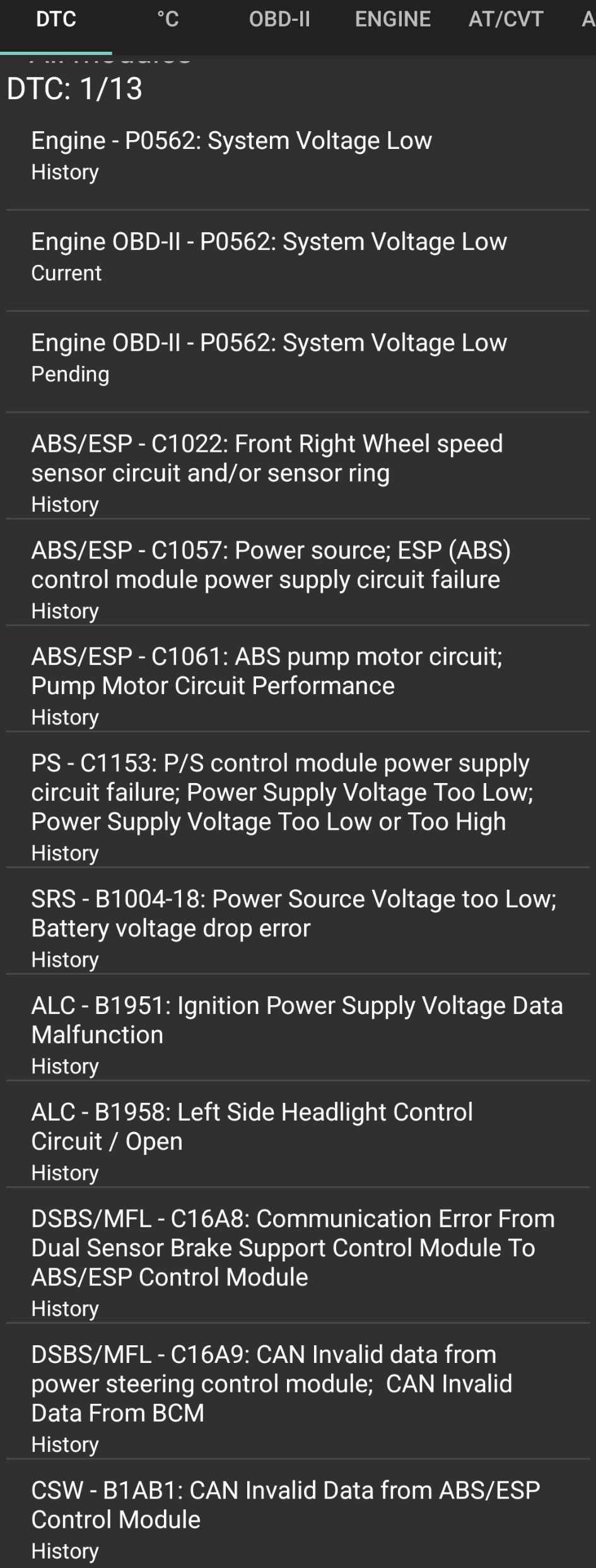
A lot of those codes are variants on “I didn’t have enough power” from each of the modules. Various modules have various cutoff voltages and potentially they will shut down before the engine itself will shut down from lack of voltage to the ECU and ignition system. Nothing problematic, just something to deal with on modern cars.
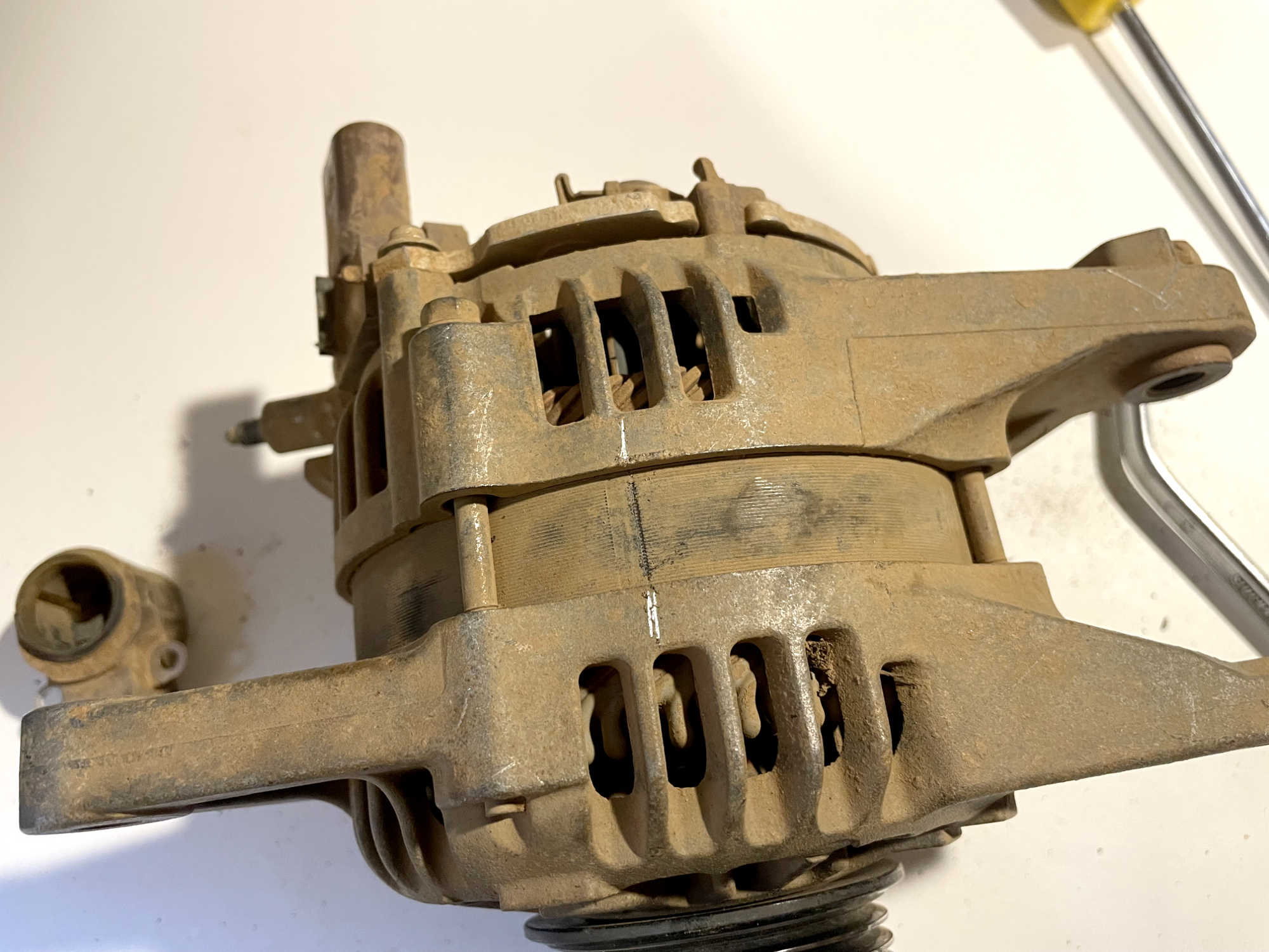
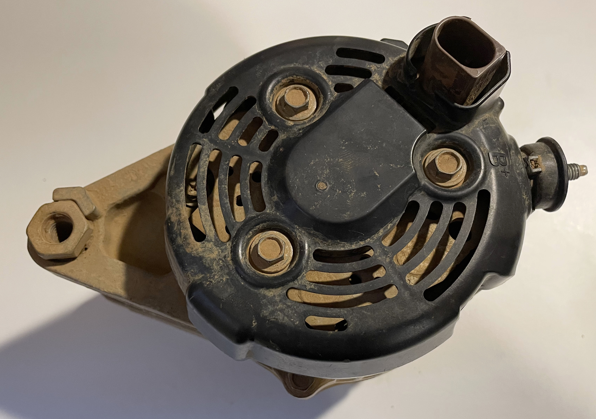
Tearing one down / fixing one up
These alternators are actually surprisingly easy to tear down, with the exception of undoing the front nut which is pretty tight from the factory. Broken ones usually have seen some abuse and so have a bunch of corrosion making dismantling a lot harder.
This dismantling is of one that was no longer charging and swapped out for another unit. I wanted to pull it down to see if there’s any advice on how you might get it working again on the side of the road or trail if you really hard to.
You will need a few tools to achieve this:
- 8 mm socket/spanner
- 22 mm spanner for undoing the front nut, or impact socket/breaker bar/chain pliers to hold the pulley, plus 10 mm 6 point socket for holding the rotor shaft while you undo the socket
(A 22 mm through socket/ratchet might actually be a great way to achieve this, while holding the rotor shaft with a 10mm 6 point 1/4″ drive socket - Flat screwdriver to help pull the terminal boot off
- JIS cross screwdriver (like a Philips head, but not) #1 for brush holder assembly
- Sandpaper and electrical contact cleaner to clean the assembly
- Drift for the front bearing if removing this from frame
- Puller for the front pulley
To allow reassambly in the same orientation with the stator assembly and front housing, mark it with a scratch mark to line everything up when you put it back together.
Teardown
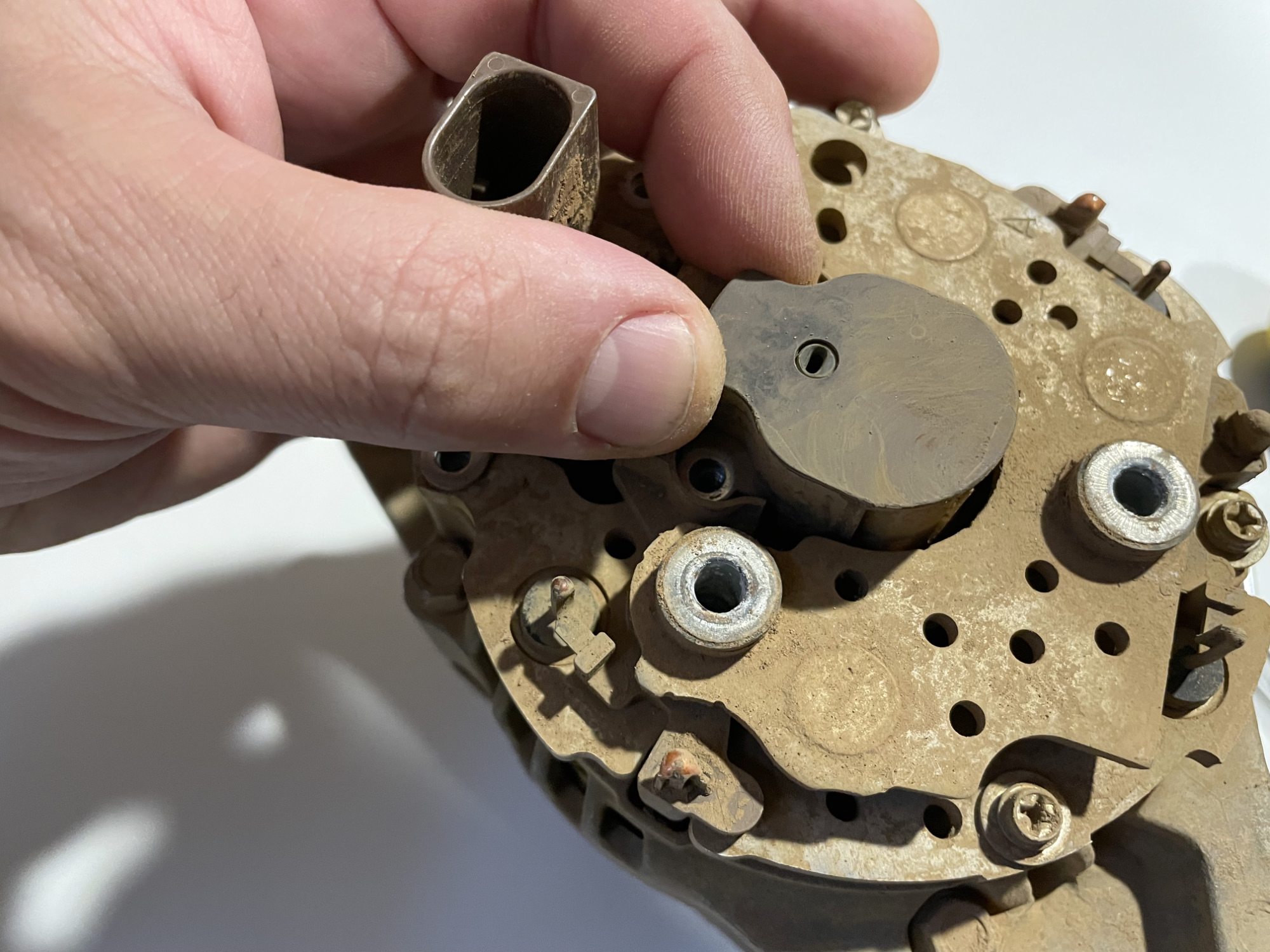
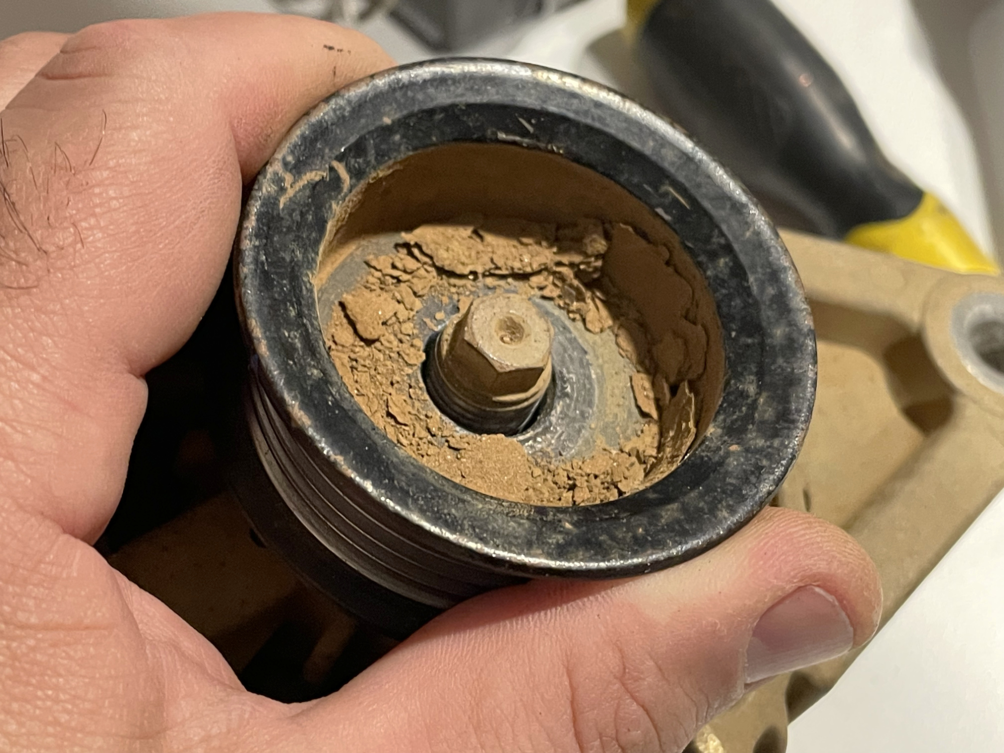
Commence by undoing the 3x 8mm headed bolts that hold the back cover on.
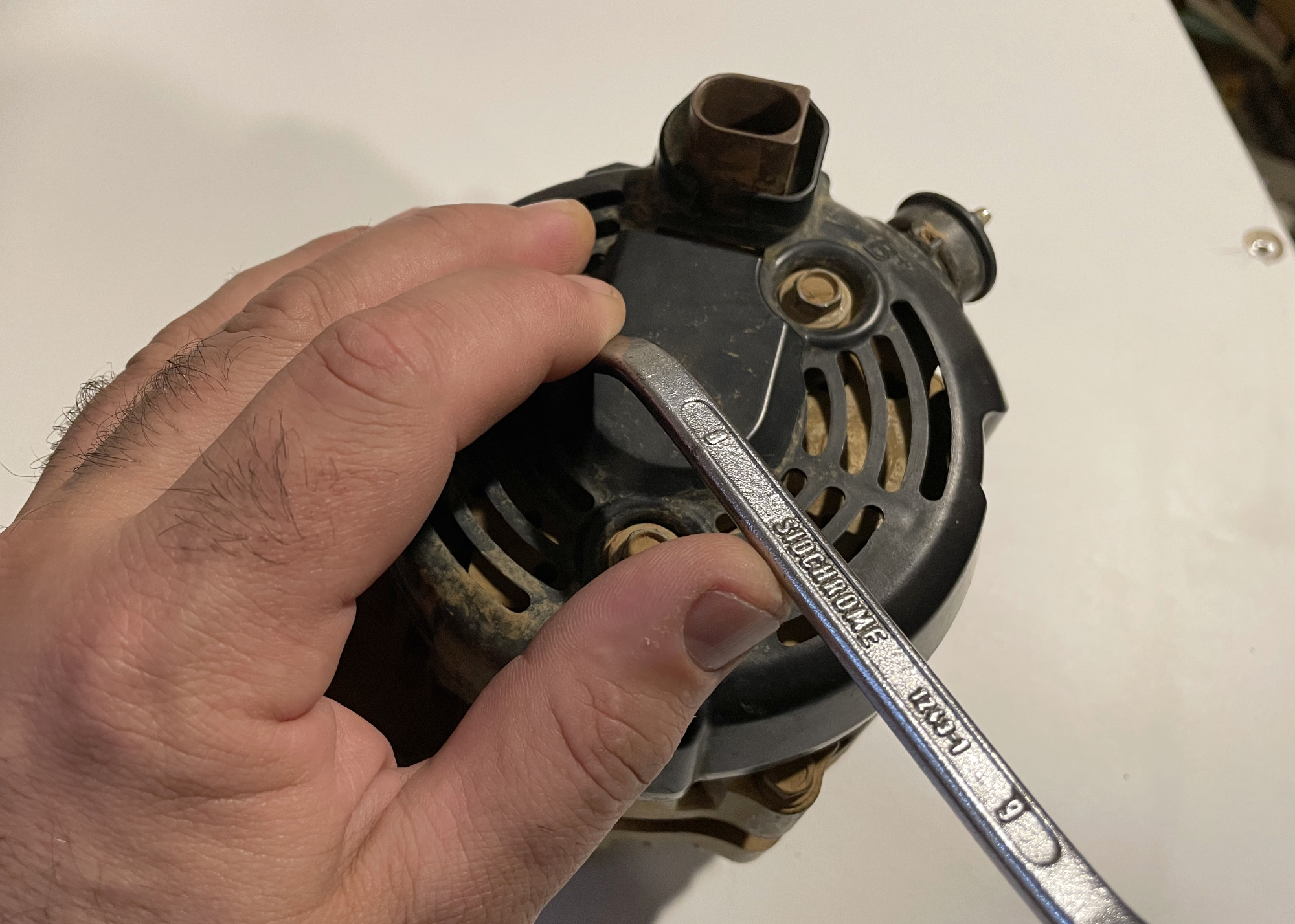
This takes a bit of a trick to get up and over the terminal base for the main battery cable. It does lift up and separate from the base of the battery connector but took me a bit of wiggling to get it to separate and come away.
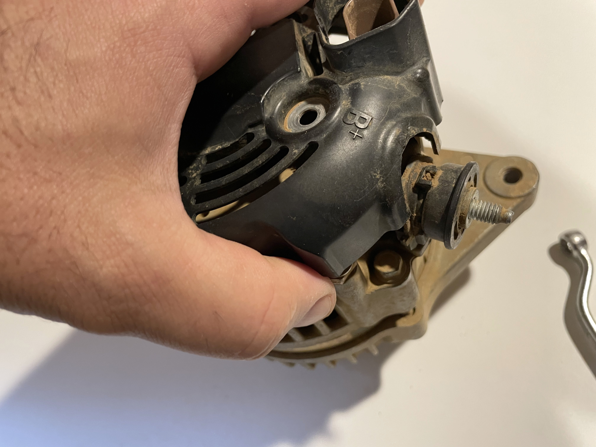
Next up is removing the brush holder with 2 screws to undo.
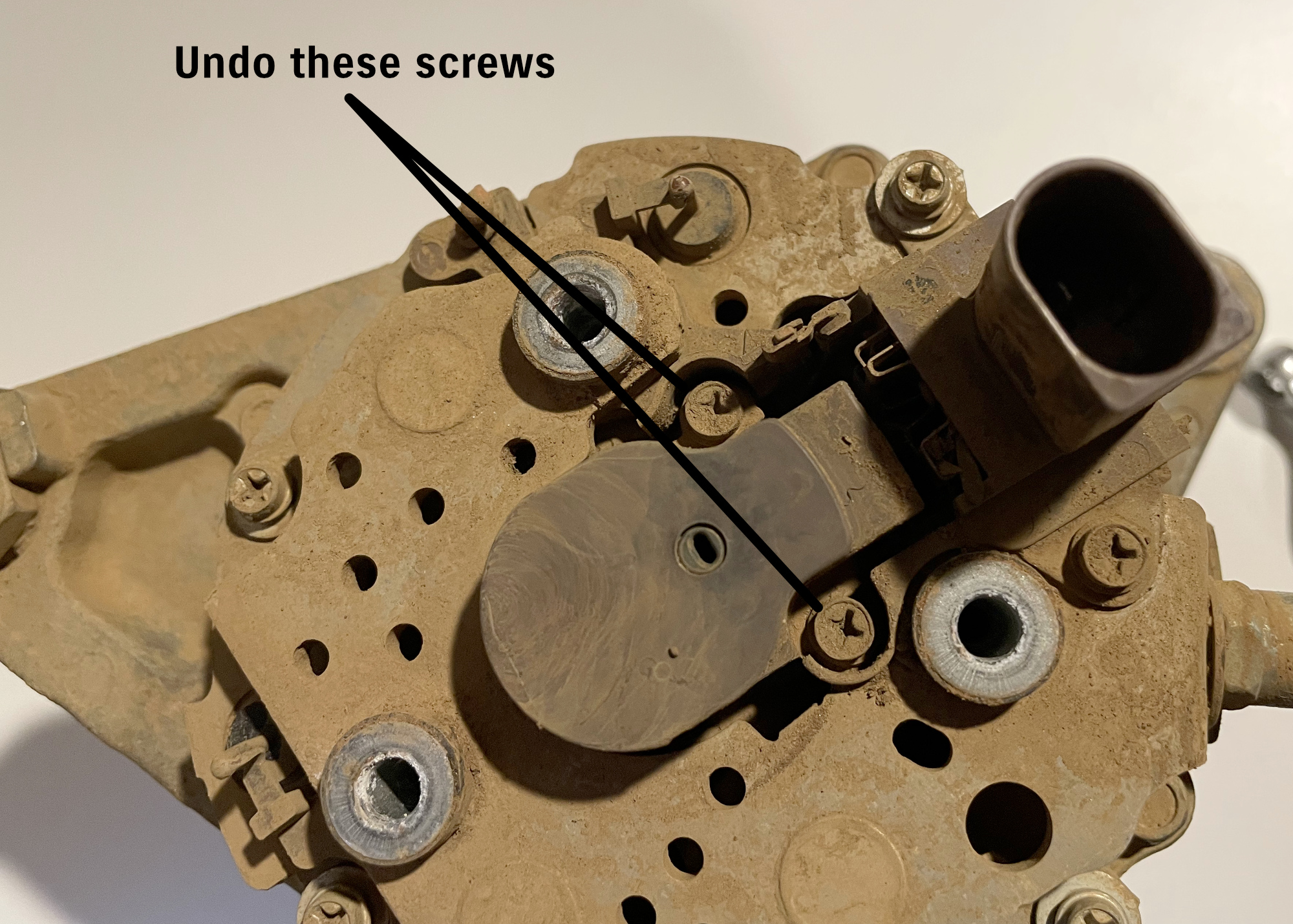
The brush holder then lifts away from the body of the alternator.
Remove the pulley nut by either holding the central part of the rotor using a 6 point (and ONLY a 6 point) 10mm socket and a large 22 mm spanner (can be hard to get one in here)…
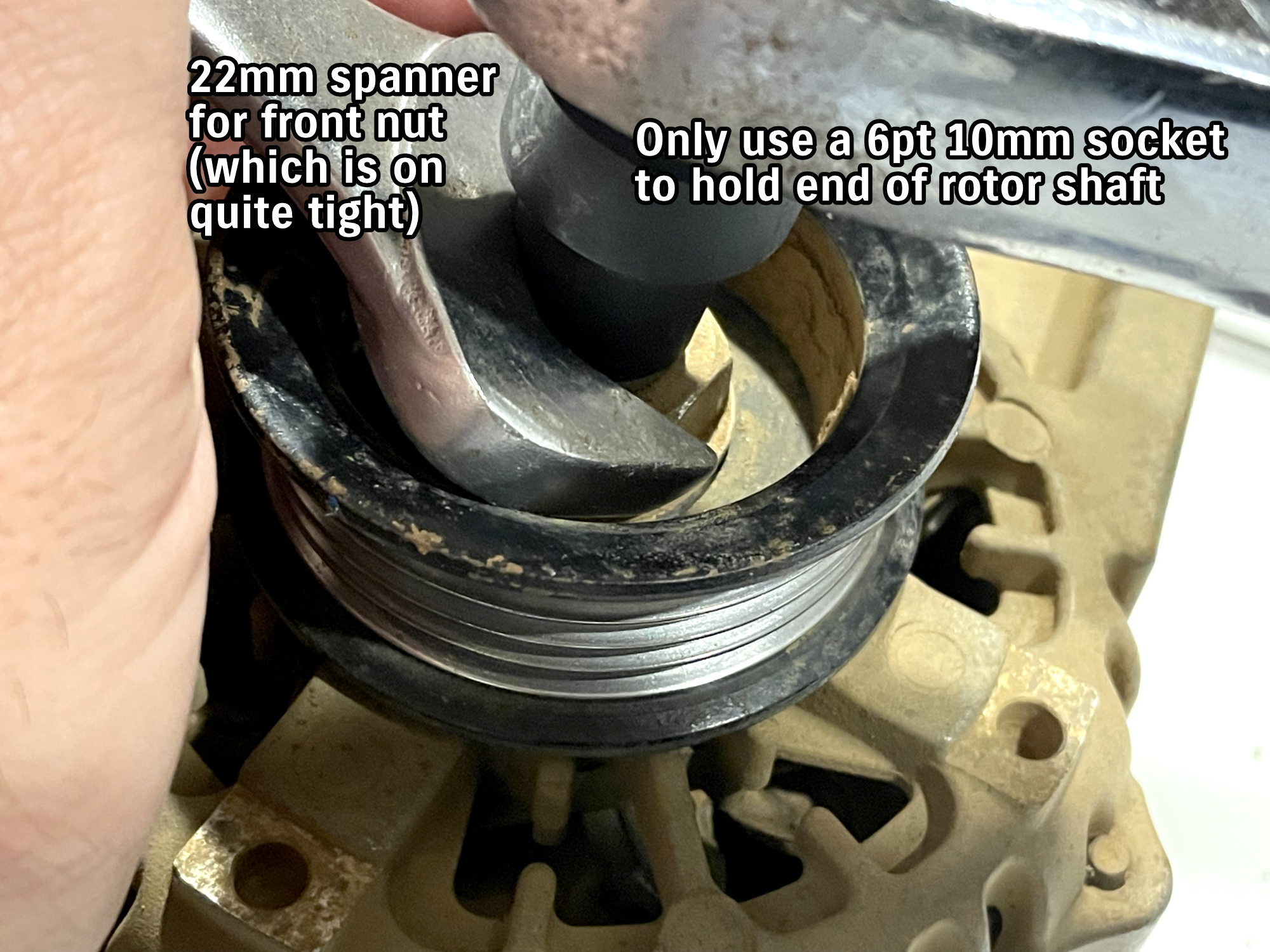
… or you can use an impact gun to remove it (or otherwise hold the pulley rather than the rotor shaft and use a breaker bar).
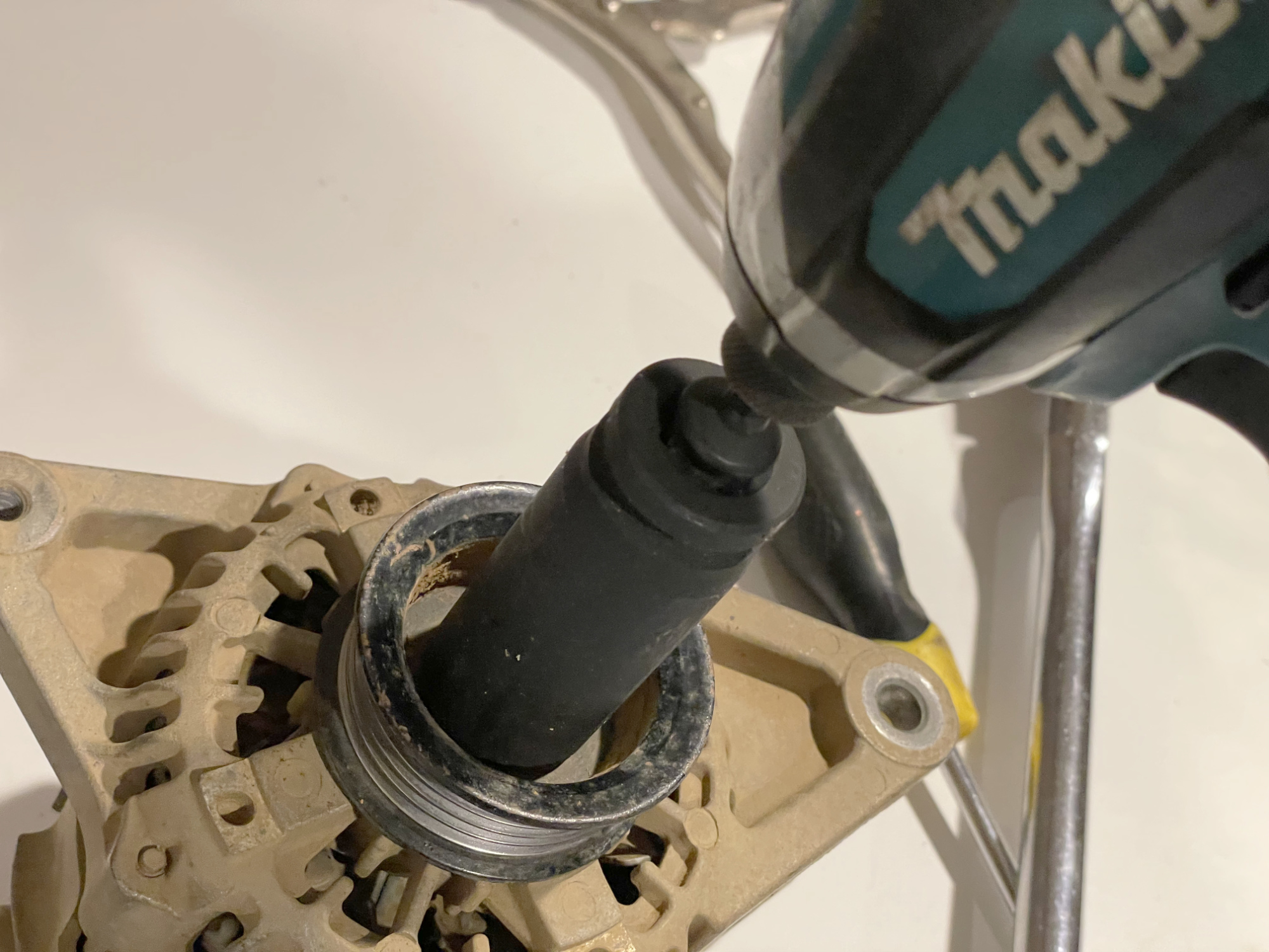
Heat and penetrating lubricant or nut busting spray can be useful here. These things are tight and get tighter from use and corrosion, though this nut came off without a fight.
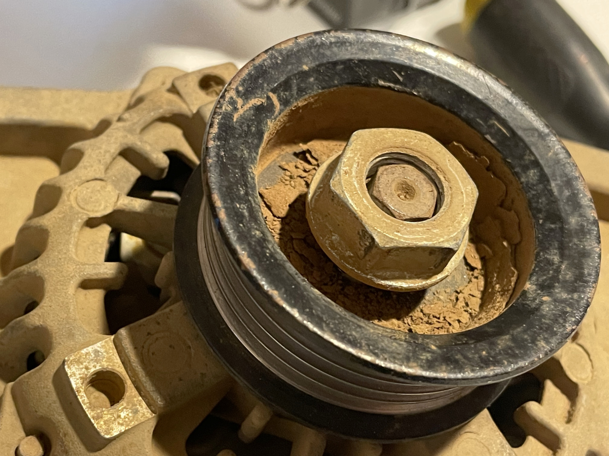
You may need to use a puller to remove the pulley from the rotor shaft, but this one slid straight off with no effort required.
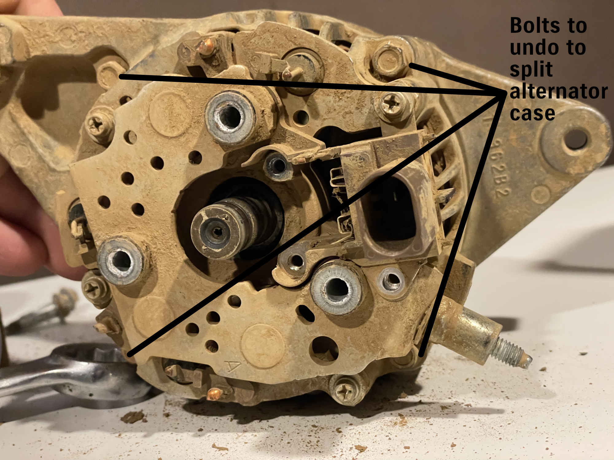
Remove the 4 bolts that hold the stator/rear casing to the front casing. You will need a relatively thin walled socket to get these.
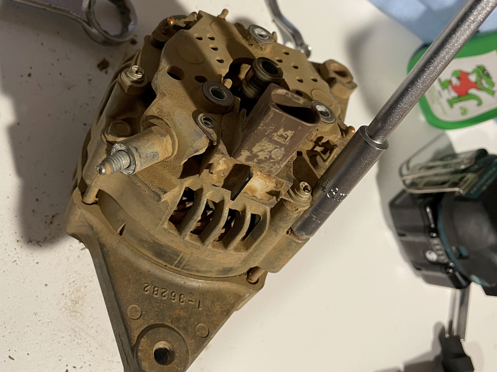
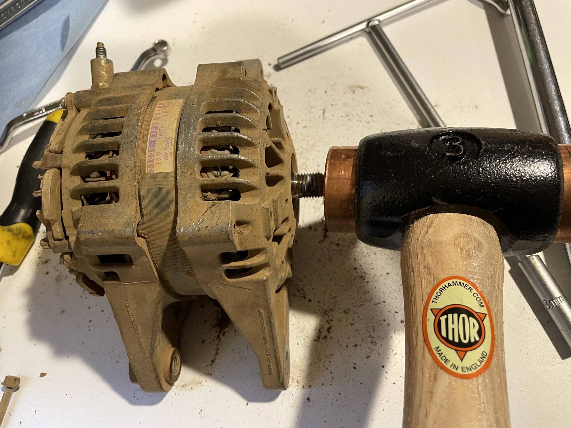
Separate the two halves of the alternator by tapping on the shaft with a hammer. Note that you should protect the shaft using wood, plastic, or using a plastic or other soft-faced hammer.
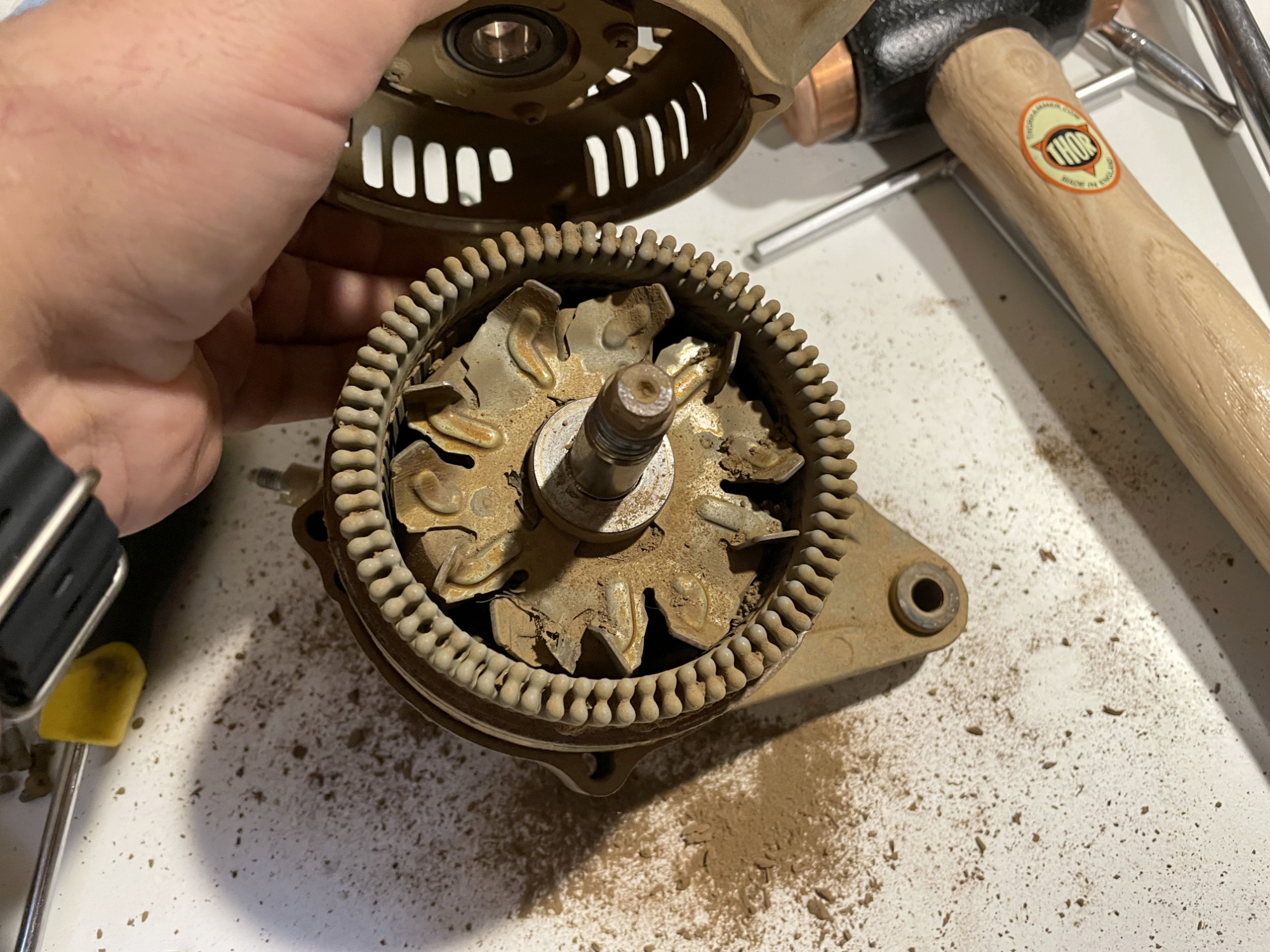
If you then tap the stator assembly gently with a plastic-faced hammer you can pull the rotor assembly clear of it. I didn’t get a photo of doing this, but if you hold the rotor by the shaft and tap on the stator/rear case assembly with somewhere for it to drop down onto you can separate it that way.
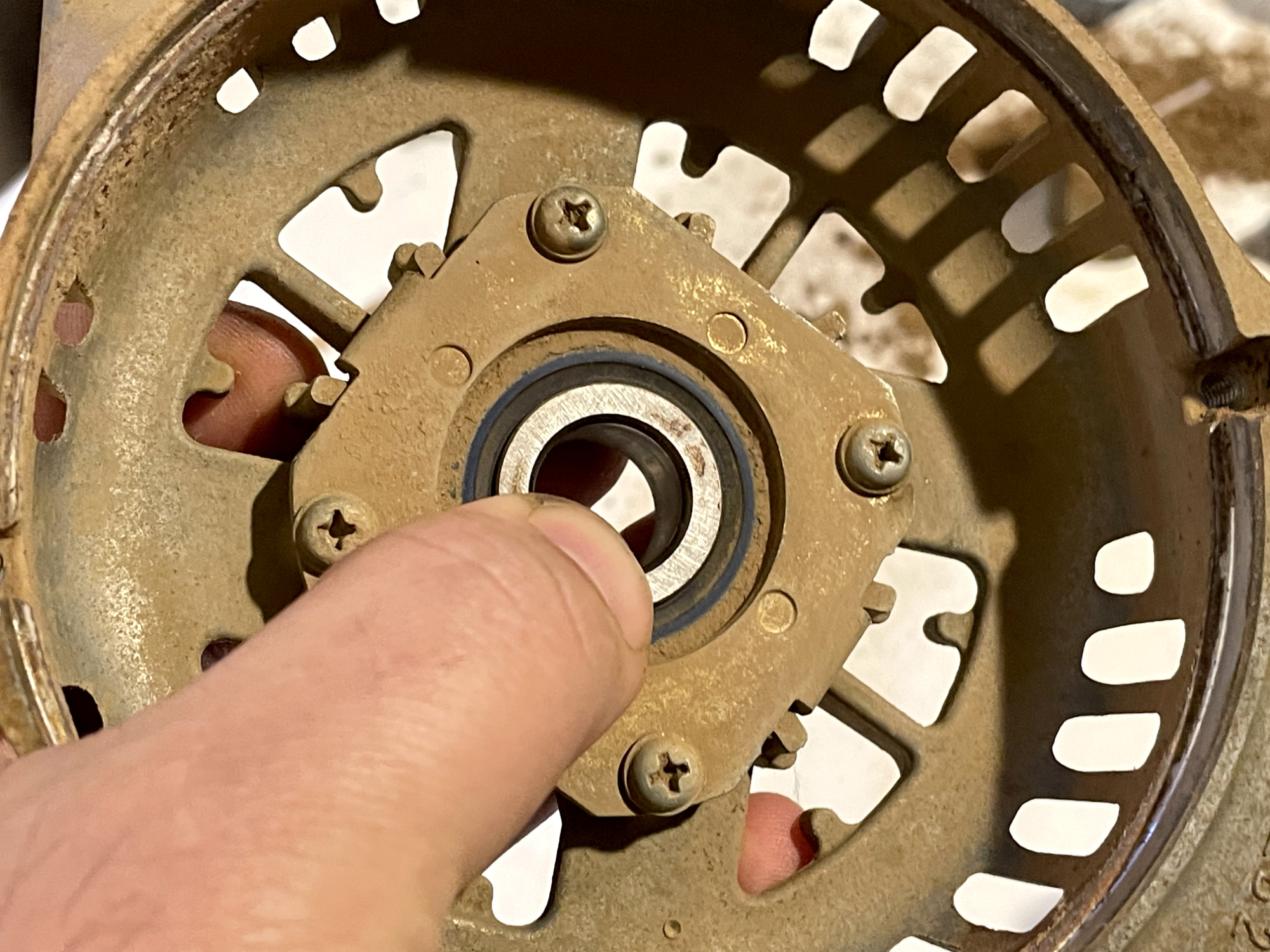
To remove the front bearing, undo the four bearing plate screws.
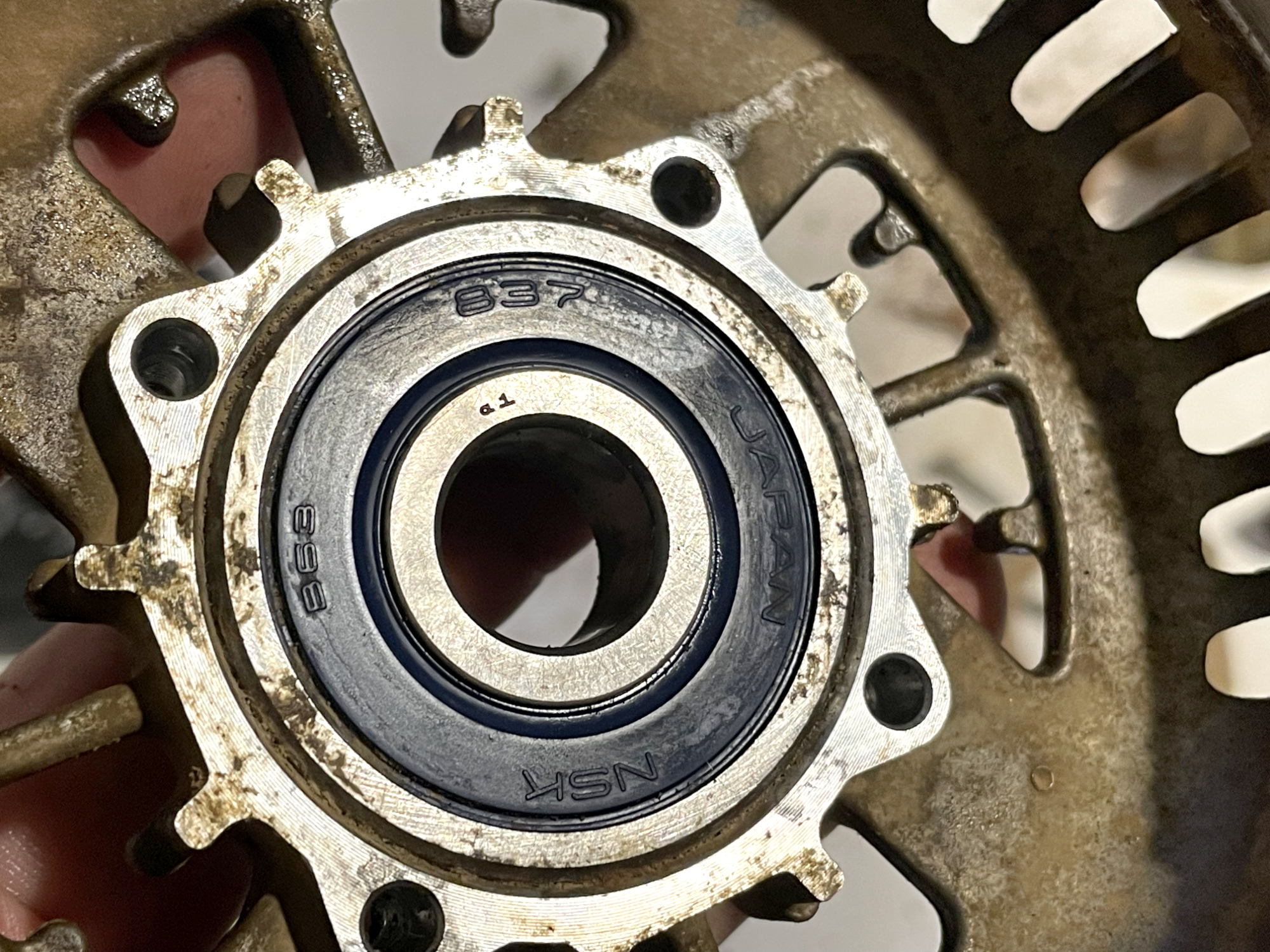
Then heat the front casing up to around 80-100 ºC and push or tap the bearing out evently using a drift or puller.
Inspection
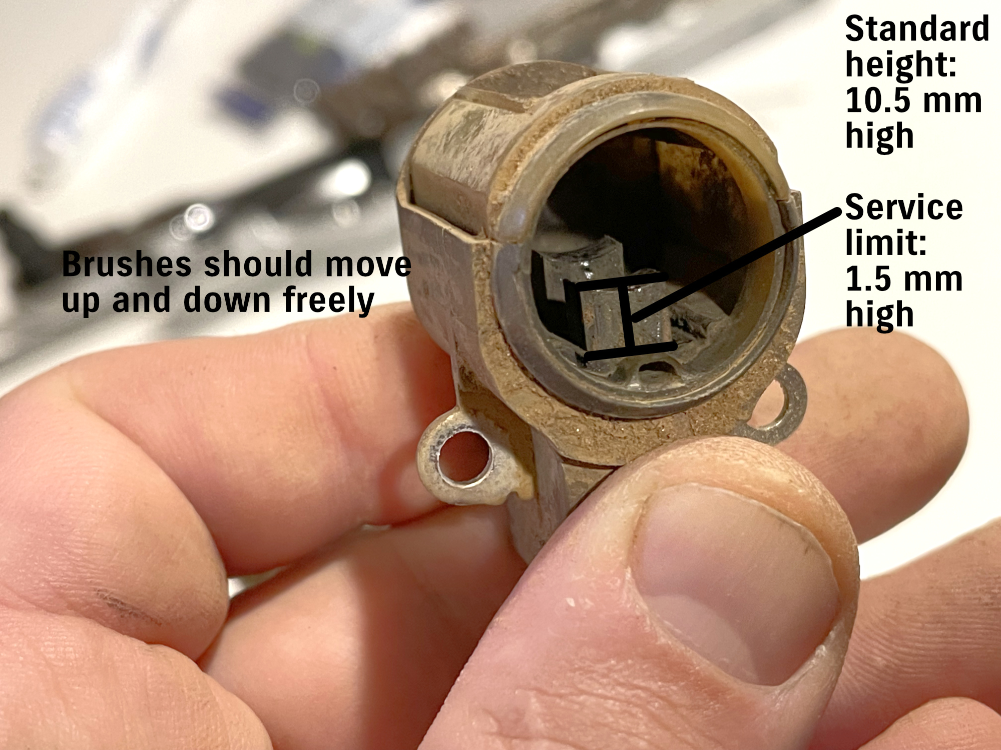
One of the key points of failure is grit getting in and stopping the brushes moving freely, or wearing them out excessively through abrasion. Inspect them in the holder; if they are stuck then you can often free them up using some isopropyl alcohol to clean out the holder & press on them with a screwdriver to unstick them so they spring back and forth.
Check the rear bearing (on the rotor shaft) for smooth movement. If it requires replacement then you replace the entire rotor. It can be pulled off but it’s quite annoying to get off.
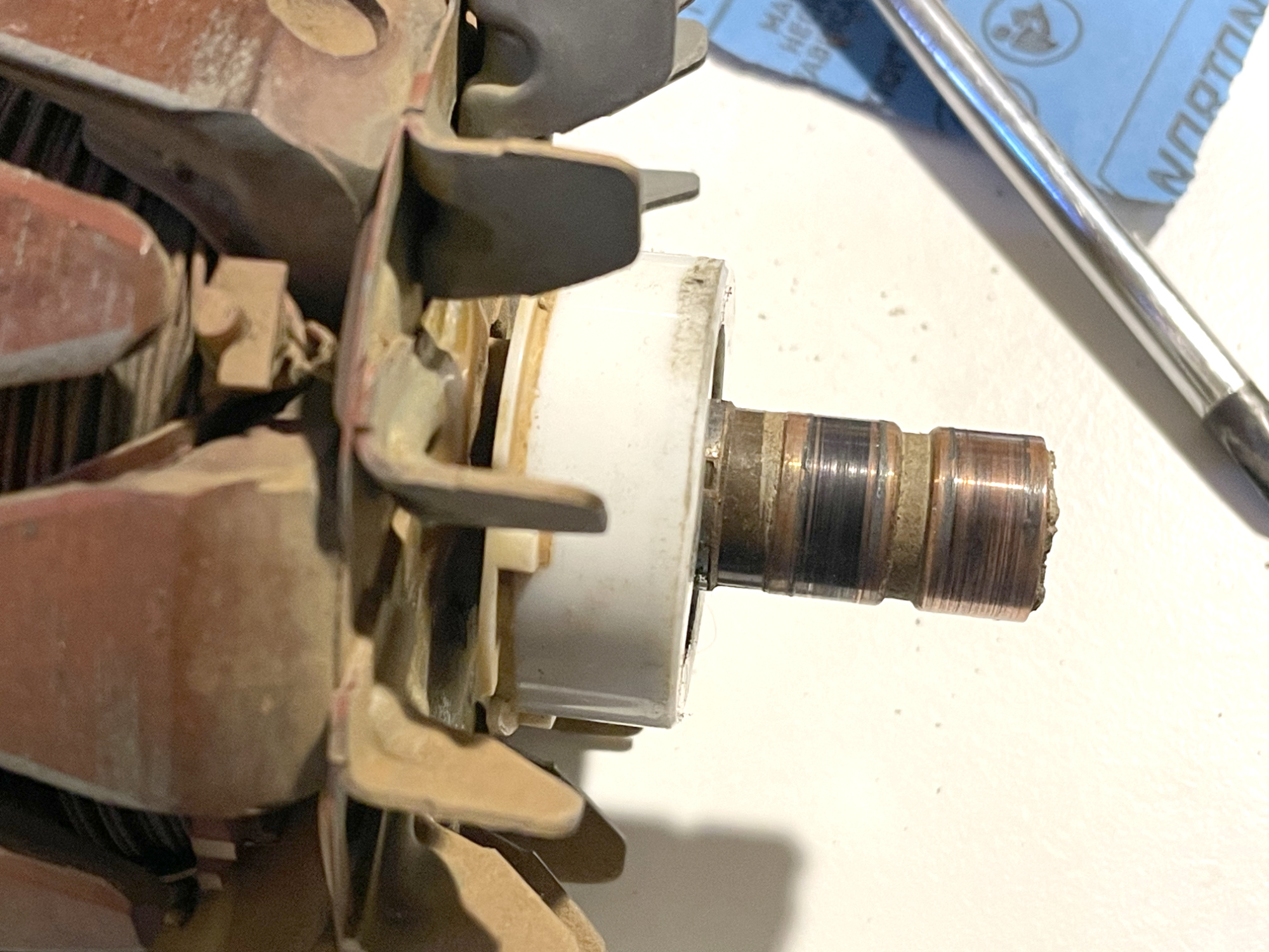
Use some emery paper or sandpaper and then electrical contact to clean up the rotor slip rings where they engage with the brushes.
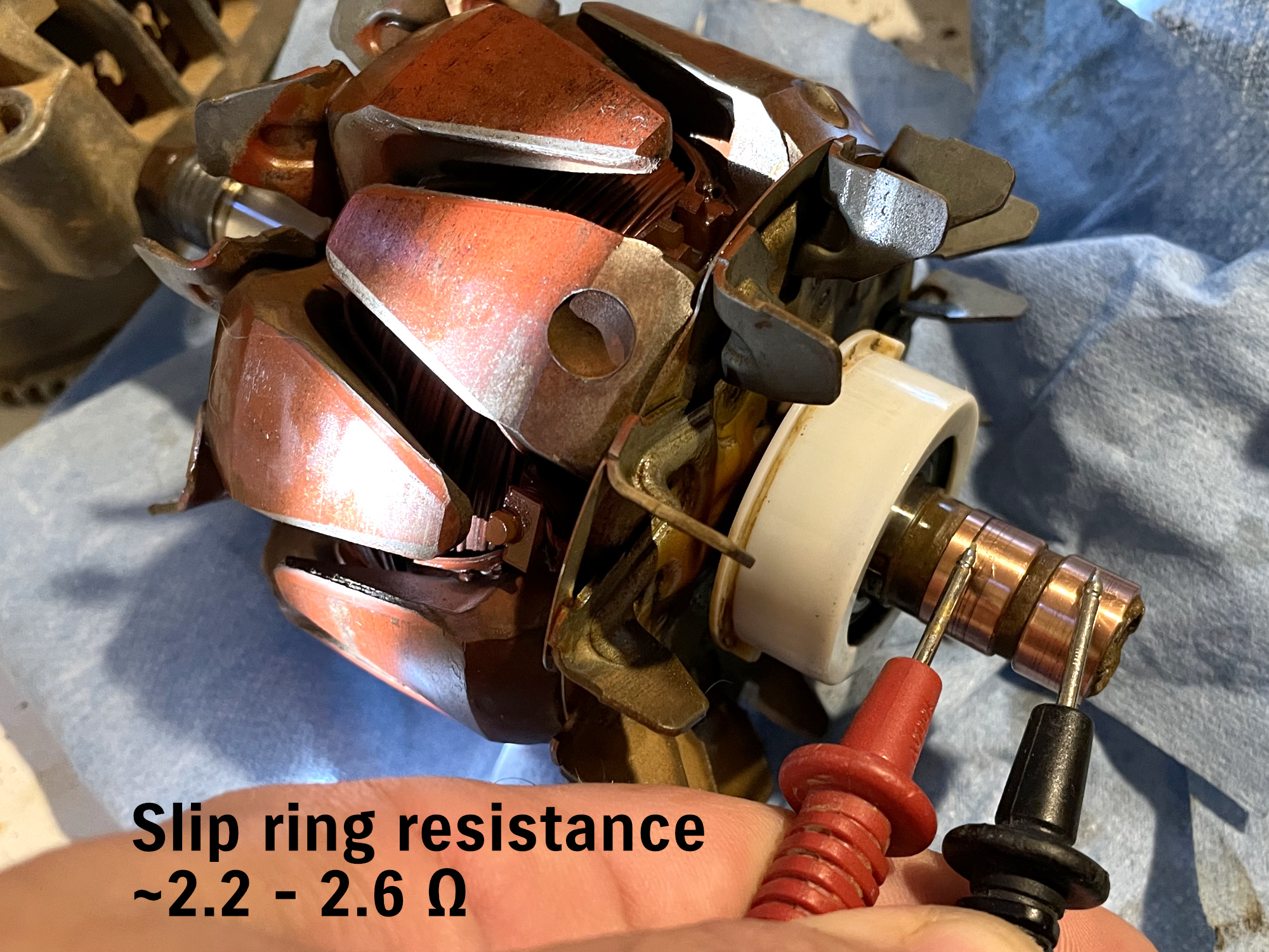
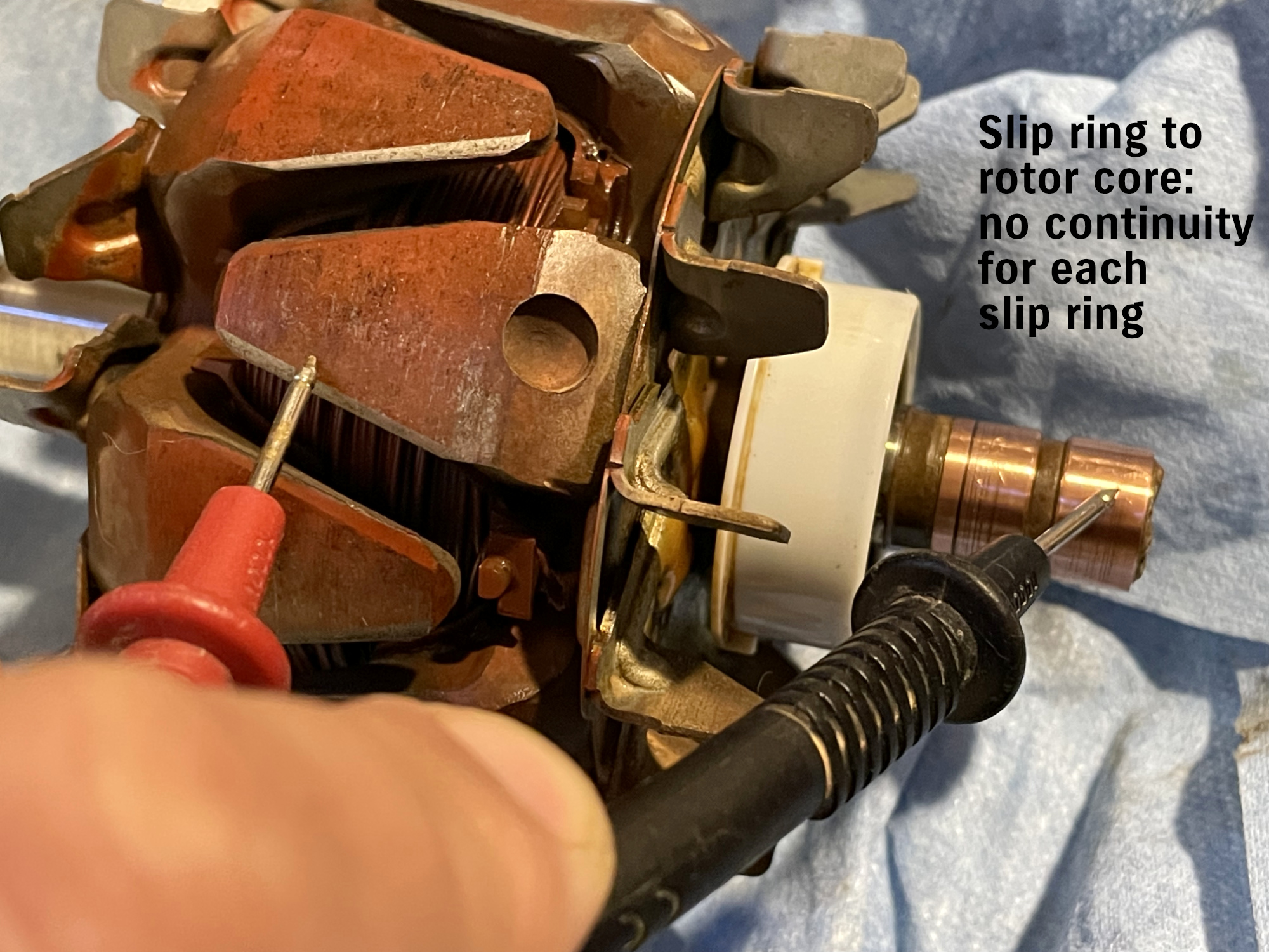
Check rotor for continuity issues. Slip ring resistance to each other is 2.2 – 2.6 Ω, and there should be no continuity to the core of the rotor.
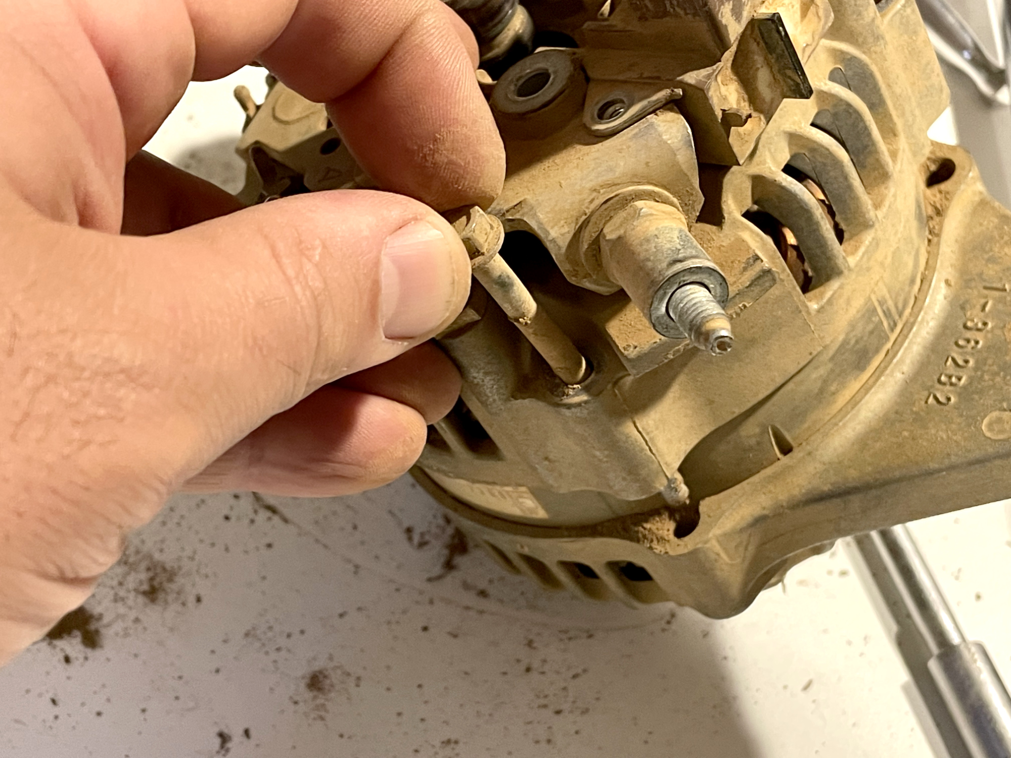
Check continuity of stator windings and rectifier diodes. To help you understand these, I’ve labelled where the winding wires come out for each phase, and also where the wires then go into the rectifier.
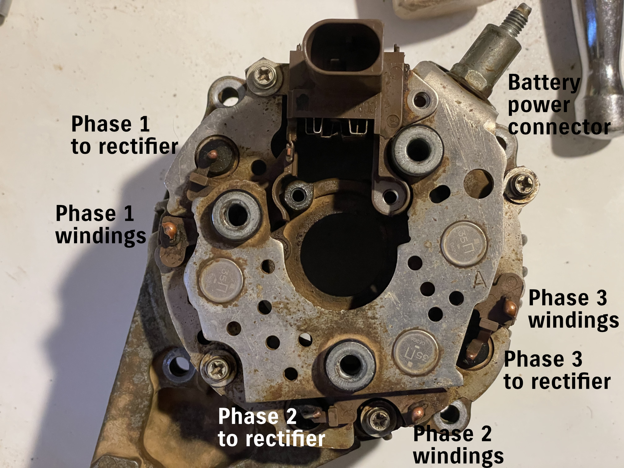
There should be some continuity between each stator winding and other phases. I measured relatively low resistances. Measure phase 1 to phase 2, phase 1 to phase 3, and phase 2 to 3. Also check resistance for each phase to its rectifier connector i.e. phase 1 wiring to phase 1 rectifier input etc.
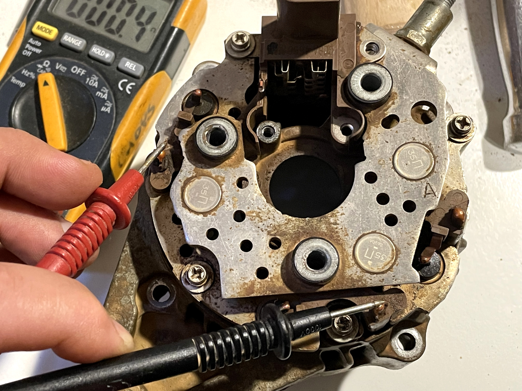
This is showing how to check for continuity between stator windings.
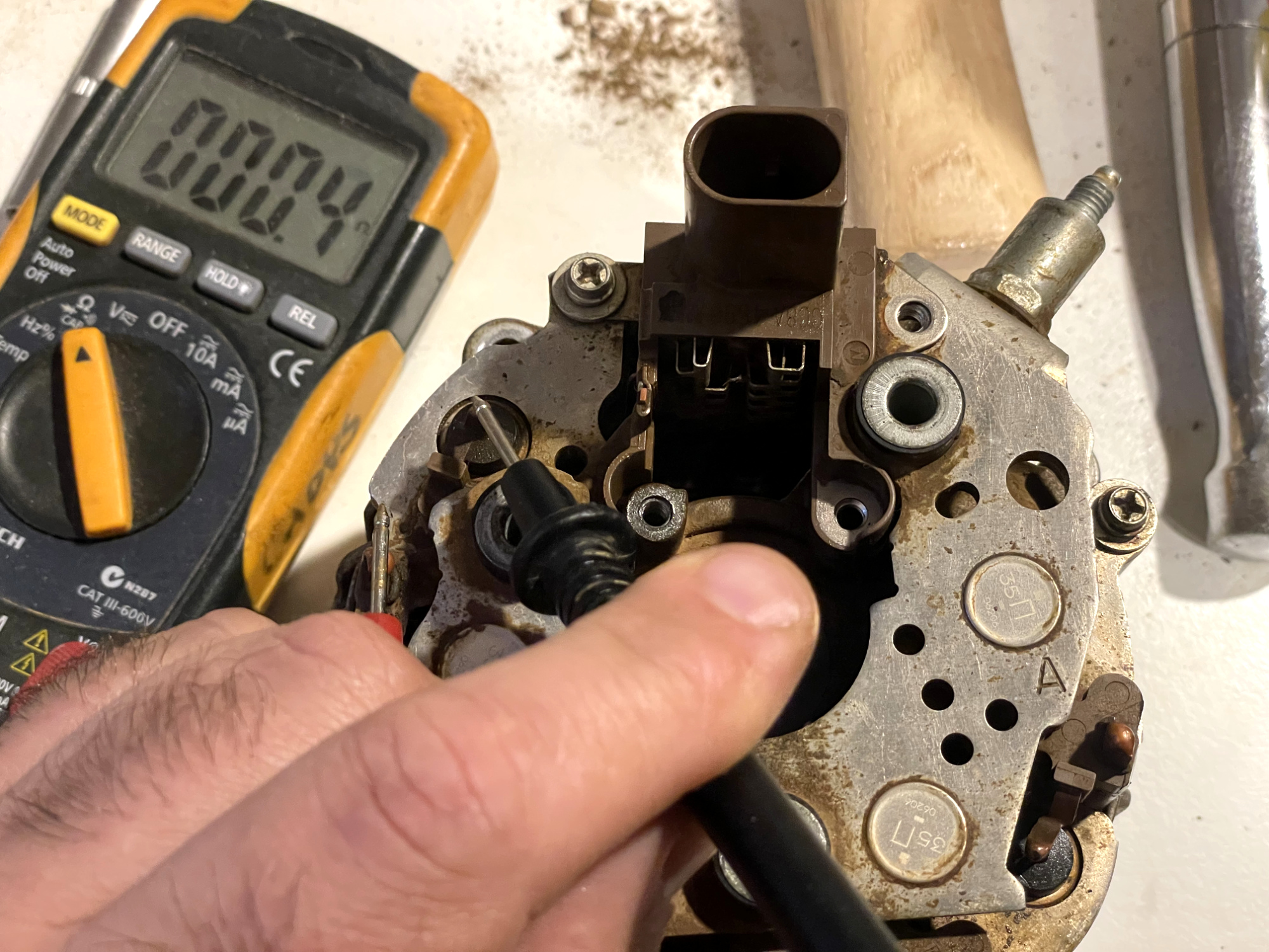
This is checking for continuity from stator winding for a phase to the rectifier input.
Also diode check battery terminal to each stator terminal. There should be continuity in only one direction for each terminal: if there is no continuity in either direction, or continuity in both directions then the stator/rear case assembly requires replacement.
Check the length on the brushes. 10 mm is standard, 1.5 mm is the limit of a worn-out brush assembly.
Reassembly
If you are changing the front bearing, heat the front casing up to 80-100 ºC and push in a new bearing.
Refit the retaining plate. Torque the screws up to 2.3 Nm if you can.
Put the rotor and rear bearing into the stator assembly.
Put on the front case, lining it up with the marks you made at the start.
Tigthen frame bolts to 6 Nm
Holding the rotor assembly using a 6 point 10 mm socket, tighten it to 130 Nm using a spanner – or hold the pulley using chain pliers (protecting the pulley with a rag or old belt) and tighten to 130 Nm using a torque wrench and 6 point 22 mm socket.