
Onboard diagnostics: codes by module
This is an open collection of codes and what they relate to for various modules. For ones I’ve seen in the wild I can potentially provide further information/diagnostic help but for others I can only go off their description and/or potential
Sections
Will be fleshed out as I add tables from my notes
- Engine
- Transmission
- Transfer case / 4wd system / front locking hubs
- Electronic stability program and anti-lock brakes (ESP/ABS)
- Power steering
- A/C system: automatic
- Air bag / restraints
- Lighting
- Gauges & controls
- Body control module
- Immobiliser
- CAN communications troubleshooting
- Anything I’ve forgotten
Yeah, it’s a lot. Deal with it.
Engine
| Code | Meaning | Troubleshooting hints |
|---|---|---|
| P0010 P2088 P2089 | P0010: “A” Camshaft Position Actuator Open P2088: “A” Camshaft Position Actuator Control Circuit Low P2089: “A” Camshaft Position Actuator Control Circuit High | Check wiring from ECU connector to cam actuator: yellow wire, C connector on ECU, pin 42. P0010: Circuit broken P2088: Circuit shorted to ground P2089: Circuit shorted to +12V Requires 3 detection cycles to activate check engine light, so codes with no check engine light might indicate intermittent faulting. |
| P0011 | “A” Camshaft Position Timing Over Advanced or System Performance | Camshaft is too advanced for too long a period. Check: * Cam actuator circuit * Oil pressure * Oil leaks from cam actuator * Cam position sensor * VVT and valve timing |
| P0016 | Crankshaft Position – Camshaft Position Correlation Bank 1 Sensor “A” | Cam to crank correlation out of range; 3 detection cycles to activate check engine light. Check: * Cam position sensor * Crank position sensor * Valve timing and/or VVT system |
| P0030 P0031 P0032 | P0030: O2 sensor 1 heater control circuit open. P0031: O2 sensor 1 heater control circuit low P0032: O2 sensor 1 heater control circuit high | O2 sensor 1 heater circuit is either broken, shorted to ground or shorted to positive power; verify wiring back to the ECU starting at the sensor on the exhaust manifold. |
| P0036 P0037 P0038 | P00036: O2 sensor 2 heater control circuit open. P0037: O2 sensor 2 heater control circuit low P0038: O2 sensor 2 heater control circuit high | O2 sensor 2 heater circuit is either broken, shorted to ground or shorted to positive power; verify wiring back to the ECU starting at the sensor on the midpipe of the exhaust. |
| P0107 P0108 | P0107: Manifold pressure circuit low P0108: Manifold pressure circuit high | Verify MAP sensor power, ground, wiring back to the ECU. |
| P0112 P0113 | P0112: Intake air temperature sensor circuit lower than 0.04 V for 10 sec. P0113: Intake air temperature sensor 1 circuit higher than 4.9 V for 10 sec. (3 D/C detection logic) | Check resistance of C-22 and C-6 pins at ECU: C-22 to C-6: < 1 Ω C-22, C-6 each to ground: infinite Voltage of C-22, C-6 approx 0 V when ignition on C-22 and other terminal at air temp sensor: infinite |
| P0116 | Coolant temperature sensor range / performance: measured coolant temp and estimated coolant temp with engine running is more than ECU parameters | Check: * Coolant level * Coolant temp sensor circuits and sensor * Thermostat |
| P0117 P0118 | P0117: coolant temperature sensor lower than 0.52 V for 5 s P0118: coolant temperature sensor higher than 4.92 V for 5 s | Check: * Resistance between pins C-20 and C-4 on ECU is < 1 Ω * Resistance between C-20 or C-4 and ground is infinite * Resistance between C-20 pin and grey wire on coolant temperature sensor is infinity * Voltage of C-20, C-4 is approx 0 V when ignition on |
| P0122 / P0123 | P0122: throttle actuator drive circuit low P0123: throttle actuator drive circuit high | Confirm: ignition ON for 10 seconds, full accelerator pedal for 2 seconds, release pedal for 2 seconds, repeat 3 times note: P0122: shouldn’t have P0123 set in this case Check: Disconnect throttle body connector * Voltage between C-15 (black) & C-13 (red) at ECU should be ~5 V, ignition on * Voltage between C-13 (red) & ground should be ~5 V Disconnect ECU connectors * C-26 (green) to ground resistance infinite * C-26 (green) circuit < 1 Ω * C-26 (green) to other pins at throttle body resistance infinite * C-26 (green) voltage ~0V when ignition on Throttle body motor * Check resistance pin 5 to 6 at connector 0.3 to 100 Ω * Apply 4.5-5 V between pin 4 (-ve) and pin 2 (+ve), -ve on multimeter to pin 4 & check voltage at pins 1 and 3 pin 1: 0.4-0.6 V @ throttle blade fully closed 0.8 – 1.0 V @ throttle blade open 8.6º from fully closed position (this is default position) 4.3-4.5 V @ throttle blade open 86º 4.4 – 4.7 V @ throttle blade fully open (93-99º open) pin 3: 4.4 – 4.6 V @ throttle blade fully closed 4.0 – 4.2 V @ throttle blade 8.6º 0.5 – 0.7 V @ throttle blade 86º 0.3 – 0.6 V @ throttle blade 93 – 99º open |
| P0130 | O2 sensor 1 (manifold) sensor value Set for these conditions: 0.05V to 0.41V for > 25 s if O2 sensor 2 (midpipe) > 0.6 V 0.6 to 1.26V for > 25 s if O2 sensor 2 (midpipe) < 0.1 V | Check O2 sensor wiring, sensors, and wiring back to ECU. |
| P0131 P0132 | O2 sensor 1 (manifold) circuit P0131: low voltage (< 0.06 V for > 25 s with O2 sensor 2 > 0.6V) P0132: high voltage (> 1.26V for > 25 s) | Check O2 sensor wiring, sensors, and wiring back to ECU. |
| P0133 | O2 sensor 1 slow response Lean to rich or rich to lean change took longer than expected | Check fuel and exhaust system for leaks Check O2 sensor circuits Check O2 sensor wiring Replace O2 sensor |
| P0134 | O2 sensor 1 no activity Output voltage of sensor stays between 0.4 and 0.6 V for > 25 s | Check fuel and exhaust system for leaks Check O2 sensor circuits Check O2 sensor wiring Replace O2 sensor |
| P0137 P0138 P0140 | O2 sensor 2 codes P0137: low voltage (lower than 0.06V for > 25 s) P0138: high voltage (higher than 1.26V for > 25 s) P0140: no activity (stays between 0.4 and 0.6 V for > 25 s) | Check fuel and exhaust system for leaks Check O2 sensor circuits Check O2 sensor wiring Replace O2 sensor |
| P0171 P0172 | P0171: fuel system too lean (fuel trim higher than specified limits for too long) P0172: fuel system too rich (fuel trim lower than specified limits for too long) | Fuel pump Fuel pressure Fuel injector circuits MAP sensor Charcoal canister purge valve PCV valve |
| P0201, P0202, P0203, P0204 P0261, P0262 P0264, P0265 P0267, P0268 P0270, P0271 | P020x: Injector circuit open for cylinder x P0261, 62: Injector circuit low, high for cylinder 1 P0264, 65: Injector circuit low, high for cylinder 2 P0267, 68: Injector circuit low, high for cylinder 3 P0270, 71: Injector circuit low, high for cylinder 4 | Fuel injector wiring Fuel injector resistances |
| P0222 P0223 | P0222: throttle position sensor sub circuit low P0223: throttle position sensor sub circuit high | Confirm: ignition ON for 10 seconds, full accelerator pedal for 2 seconds, release pedal for 2 seconds, repeat 3 times note: P0222: shouldn’t have P0223 set in this case Check: Disconnect throttle body connector * Voltage between C-15 (black) & C-13 (red) at ECU should be ~5 V, ignition on * Voltage between C-13 (red) & ground should be ~5 V Disconnect ECU connectors * C-26 (green) to ground resistance infinite * C-26 (green) circuit < 1 Ω * C-26 (green) to other pins at throttle body resistance infinite * C-26 (green) voltage ~0V when ignition on Throttle body motor * Check resistance pin 5 to 6 at connector 0.3 to 100 Ω * Apply 4.5-5 V between pin 4 (-ve) and pin 2 (+ve), -ve on multimeter to pin 4 & check voltage at pins 1 and 3 pin 1: 0.4-0.6 V @ throttle blade fully closed 0.8 – 1.0 V @ throttle blade open 8.6º from fully closed position (this is default position) 4.3-4.5 V @ throttle blade open 86º 4.4 – 4.7 V @ throttle blade fully open (93-99º open) pin 3: 4.4 – 4.6 V @ throttle blade fully closed 4.0 – 4.2 V @ throttle blade 8.6º 0.5 – 0.7 V @ throttle blade 86º 0.3 – 0.6 V @ throttle blade 93 – 99º open |
| P0300 P0301 P0302 P0303 P0304 | P0300: misfire, random cylinder (on 2 or more cylinders) P030x: misfire, cylinder x Misfire is detected for: * catalyst overheating for > 200 engine revs * exhaust emission effected for > 1000 engine revs | Confirm: Check engine light blinks Check: * Sufficient, quality fuel in tank * Air intake and exhaust leak check * Coil wiring * Fuel injector wiring * Swap coils to see if misfire moves cylinders * Replace spark plugs * Engine compression * Valve clearances * Valve timing |
| P0327 P0328 | Knock sensor low, high | Check: * Knock sensor wiring At ECU pin C-25 (white) and C-37 (blue), not shorted to ground & ~0V when ignition is on |
| P0335 P0336 | P0335: Crank position sensor signal not detected when cam position is P0336: Blank portion of timing wheel not detected in correct location | Check: * Crank position sensor circuit power: voltage between blue wire (blue wire, from main relay) and C-39 (pink, at ECU) is battery voltage * Wiring for crank position sensor not grounded or shorted to battery voltage * Valve timing |
| P0340 | Camshaft position sensor A issue (cam position signal not received) | Check: * Cam position sensor wiring |
| P0351, P0352, P0353, P0354 P2300, P2301 P2303, P2304 P2306, P2307 P2309, P2310 | P035x: Ignition coil cylinder x open circuit P2300-01: Ignition coil cylinder 1 low, high P2303-04: Ignition coil cylinder 2 low, high P2306-07: Ignition coil cylinder 3 low, high P2309-10: Ignition coil cylinder 2 low, high | Check: ignition coil wiring from ECU drive circuits, ignition coils |
| P0420 | Catalyst efficiency below threshold | Check: * Manifold and midpipe O2 sensors and their wiring |
| P0443 P0458 P0459 | P0443: Evaporative emissions system control valve open circuit P0458: Evaporative emissions system control valve circuit low P0459: Evaporative emissions system control valve circuit high | Check: * Evap control valve wiring at ECU (C-41, grey) for shorts/grounding/breaks * Resistance of evap control valve should be 22-26 Ω at terminals on control valve |
| P0480 P0692 | P0480: Low speed radiator fan open circuit or shorted to ground P0692: Low speed radiator fan circuit shorted to battery +ve | Does not display check engine light. Check wiring to radiator fan relay, documented on my page on understanding the cooling system of the Jimny. |
| P0481 P0694 | P0481: High speed radiator fan open circuit or shorted to ground P0694: High speed radiator fan circuit shorted to battery +ve | Does not display check engine light. Check wiring to radiator fan relay, documented on my page on understanding the cooling system of the Jimny. Note: this could relate to either the high speed power relay or the high speed grounding relay. |
| P0500 | Vss signal slower than 4 km/h for 12.7 s when engine braking | Confirm: With engine warm and no errors P0116, P0117, P0118, P0335 or P0340, drive > 60 km/h and release accelerator pedal for > 10 s Check: * Any error codes in ABS/ESP module * Wheel speed sensors wiring |
| P0504 | Brake light switch correlation error | Brake light switch signal does not correlate with brake pedal switch signal Check: * Wiring of brake light switch * Operation of brake light switch |
| P0515 | Battery temperature sensor circuit: lower than 0.10V or higher than 4.85V for > 5s | Check: * Wiring at battery temperature/current sensor * Electrical load sensor resistance between pins 1 and 4 should be: – 1.9-2.1 kΩ @ 25ºC – < 0.25 kΩ @ 90ºC with an exponential type decay curve |
| P0530 | A/C refrigerant pressure circuit < 0.15 V or > 4.93 V (check engine light is not displayed) | Check: * Wiring of refrigerant pressure sensor * Refrigerant pressure sensor |
| P0560 P0562 P0563 | P0560: Main voltage < 2.54 V for > 10 s P0562: Main voltage < 9.8 V for > 10 s with engine running P0563: Main voltage > 18.1 V for > 10 s with engine running | Confirm: P0560 – ignition on for > 60 s 562/563 – engine on > 2500 rpm for > 60 s Check: * Battery voltage and battery condition * Charging system * Main system relays and fuses |
| P0602 | ECU programming error | If after reprogramming ECU this indicates ECU is not correctly reprogrammed, or may indicate ECU failure Check: * Power and ground circuits to ECU |
| P0606 | ECU internal processor failure | Confirm: Ensure battery voltage > 8.5V and < 16.5 V Idle engine for > 60 s Check: * Power and ground circuits to ECU * 2nd O2 sensor (midpipe) needs replacement |
| P0607 | Internal ECU failure | Confirm: Battery voltage is > 8 V and engine starts (if possible) Check: * ECU power and ground circuits |
| P0645 P0646 P0647 | A/C clutch control circuit P0645: open P0646: low P0647: high | Check: * A/C compressor relay and circuit * Wiring to A/C compressor |
| P0A5A | Electrical load sensor < 0.2 V or > 4.8 V for > 5 s, or fluctuates less than expected for 5 s | Check: * Electrical load sensor (with ignition on) – Voltage should be ~5 V between light blue and brown wires at load sensor – Voltage between light blue and ground ~5 V * Battery current detected on scantool should be: – 2-8 A ignition on – 14-22 A + headlight on – 22-33 A + heater fan on maximum speed * If battery sensor is disconnected, voltage should vary with electrical load: 3.4 V ignition on, 3.1 V for ignition on, headlight on, heater at max speed |
| P1693 | Information mismatch (ABS/ESP control module and gauge cluster not matched | Check: Required part numbers/software versions of gauge and ESP modules Replace gauge cluster with known good cluster |
| P2100 | Primary throttle plate actuator open circuit | Check: * Wiring of electronic throttle body back to ECU |
| P2101 P2119 | P2101: Throttle actuator control circuit range/performance Difference between measured and target throttle position different Duty ratio of throttle actuator signal out of range P2119: Throttle actuator control range/performance Time taken for throttle valve to return from partially open to mechanical default position is more than specified time during ignition off Measured default throttle position (idle position) is out of range | Check: * Throttle actuator drive circuits * Electronic throttle body physical assembly |
| P2122 P2123 | Accelerator pedal position main sensor low (P2122: < 0.4 V) or high (P2123: > 4.8 V) | Check: * Accelerator pedal assembly * Accelerator pedal wiring (If throttle controller afixed, remove controller and verify if DTCs reoccur after clearing) |
| P2127 P2128 | Accelerator pedal position sub sensor low (P2127: < 0.2 V) or high (P2128: > 2.4 V) | Check: * Accelerator pedal assembly * Accelerator pedal wiring (If throttle controller afixed, remove controller and verify if DTCs reoccur after clearing) |
| P2135 | Throttle plate position sensor primary and secondary correlation error | Check: * Accelerator pedal assembly * Accelerator pedal wiring * Electronic throttle body (If throttle controller afixed, remove controller and verify if DTCs reoccur after clearing) |
| P2138 | Accelerator pedal position main and sub sensor correlation error | Check: * Accelerator pedal assembly * Accelerator pedal wiring * Electronic throttle body (If throttle controller afixed, remove controller and verify if DTCs reoccur after clearing) |
| P2176 | Electronic throttle body idle position not learned Occurs when primary and secondary throttle plate position sensors are out of range at default position for too long. | Check: * Electronic throttle body calibration has been performed * Check wiring harness from ECU to throttle body |
| P2226 P2227 | Barometric pressure sensor circuit out of range (P2226) or range/performance issue (P2227) | P2227 occurs with sensor signal outside of range, or sensor values fluctuates more than tolerance; P2226 is related to shorted to ground, power supply or open circuit Check: * Engine and emissions control systems * Replace ECU if persists (as barometric pressure sensor is part of ECU) |
| P2271 | O2 sensor 2 (midpipe) biased or stuck rich | Check: * 2nd O2 sensor wiring * Exhaust and intake system for leaks * Engine compression * Spark plugs * Fuel pressure * Evap purge valve * MAP sensor * PCV system * Fuel injectors and circuits |
| U0073 U0101 U0114 U0121 U0131 U0140 U0155 U1093 U2001 U2021 | Lost CAN/LIN signal U0073: ECU cannot transmit/receive on CAN U0101: ECU <-> TCM U0114: ECU <-> 4wd module U0121: ECU <-> ABS/ESP module U0131: ECU <-> power steering U0140: ECU <-> BCM U0155: ECU <-> gauges U1093: ECU <-> autonomous braking U2001: ECU <-> alternator via LIN U2021: Invalid data ECU to alternator via LIN | Check CAN wiring through each module to verify no errors in the network daisy-chain |
Transmission
| Code | Meaning | Troubleshooting hints |
|---|---|---|
| P0602 | TCM programming error | Internal failure of the TCM relating to programming/firmware. If no other codes then potentially replace TCM and/or have it reprogrammed at a Suzuki service centre. |
| P062F P1702 | P062F: EEPROM error P1702: Internal memory checksum error | Check for any wiring issues from transmission wiring harness; substitute TCM for known working TCM if error is not intermittent. (If intermittent, might still require TCM replacement). |
| P0705 | Transmission range sensor: multiple signals are input for > 4 s | Check: * Adjustment of shift linkage/cables * Wiring of transmission harness back to the TCM (Once I have access to an automatic for a few hours I’ll draw up the wiring diagram relevant for this code). * Replace TCM if no wiring or shift linkage issues |
| P0707 | Transmission range sensor circuit no signal for > 28 s | Check: * Wiring of transmission harness back to the TCM * Adjustment of shift linkage/cables * Verify position/calibration of range sensor * Replace TCM if no wiring or shift linkage issues |
| P0711 | Transmission fluid temperature sensor range/performance (no change driving > 600 s after speed > 40 km/h) | Check: * Wiring of ATF temperature sensor * Replace temperature sensor if not wiring * Replace TCM with known good if no issue with sensor wiring or sensor |
| P0712 | Transmission fluid temperature sensor circuit low | Check: * Wiring of ATF temperature sensor * Replace temperature sensor if not wiring * Replace TCM with known good if no issue with sensor wiring |
| P0713 | Transmission fluid temperature sensor circuit high | Check: * Wiring of ATF temperature sensor * Replace temperature sensor if not wiring * Replace TCM with known good if no issue with sensor wiring |
| P0717 | Input shaft / turbine speed sensor circuit no signal | Confirmation of DTC requires driving at 40 km/h for 10 minutes Check: * Transmission control system * Wiring of sensor to TCM * Replace sensor if not wiring * Replace TCM |
| P0722 | Output shaft speed sensor circuit no signal | Confirmation of DTC requires driving at 40 km/h for 10 minutes Check: * Transmission control system * Wiring of sensor to TCM * Replace sensor if not wiring * Replace TCM |
| P0741 P0742 | P0741: Torque converter clutch circuit performance / TCC stuck off P0742: Torque converter clutch circuit performance / TCC stuck on | This can be a common error for fluid contamination especially from mud driving/water crossings Check: * First warm up vehicle and drive at constant throttle at a speed of 50 – 80 km/h for 1 minute with transmission selector in D * Drive vehicle at 50 – 100 km/h; depress accelerator, engine speed and input shaft speed should differ by > 100 rpm for 3 s or so * Check ATF level and quality; change transmission fluid if contaminated * Remove valve body and check lockup solenoid performance * Clean valve body * Replace converter if persists |
| P0751 P0752 P0756 P0757 | P0751: Shift solenoid A performance / stuck off (3rd detected, 2nd commanded) 52: Shift solenoid A stuck on (2nd detected, 3rd commanded) 56: Shift solenoid B performance / stuck off (4th detected, 3rd commanded) 57: Shift solenoid B stuck on (3rd detected, 4th commanded) | This can be a common error for fluid contamination especially from mud driving/water crossings Verify: * Clear all DTCs * Start car and warm up to full operating temperature * Cycle gears between P, R, N and D when parked * Drive up to 65 km/h with 10% or more throttle * Freeze frame data Check: * Check ATF level and quality; change transmission fluid if contaminated * Remove valve body and clean it, check solenoids for operation, clean fluid passageways in transmission |
| P0787 P0788 | P0787: Shift timing solenoid A low 88: Shift timing solenoid A high | Check: * Solenoid drive circuit wiring * Solenoid resistance * Replace TCM with known good TCM if not otherwise working |
| P0961 P0962 P0963 | P0961: Pressure control solenoid control circuit range / performance 62: Pressure control solenoid control circuit low 63: Pressure control solenoid control circuit high | Check: * Pressure control solenoid drive circuit wiring * Pressure control solenoid resistance * Replace TCM with known good TCM if not otherwise working |
| P0973 P0974 P0976 P0977 | P0973: Shift solenoid A control circuit low 74: Shift solenoid A control circuit high 76: Shift solenoid B control circuit low 77: Shift solenoid B control circuit high | Check: * Solenoid drive circuit wiring * Solenoid resistance * Replace TCM with known good TCM if not otherwise working |
| P1706 | Torque request comms error from TCM to ECU | Check: * TCM and ECU wiring * Check for other DTCs and troubleshoot as appropriate |
| P1874 | 4wd low switch malfunction (TCM logic detects 4H with 4L switch shorted to ground) | Note: This error can appear if you try to fool an automatic car into thinking it is in high range when it is in low range, e.g. for 2WD low range . The car looks at road speeds versus what gear it is in and engine RPM to determine if you’re doing something strange. Check: * Wiring of low range switch/sensor |
| P1875 | 4wd low switch malfunction (TCM logic detects 4L in 2H or 4H) | Note: This error can appear if you try to fool an automatic car into thinking it is in 4L when it is in 4H to disable traction control in high range. The car looks at road speeds versus what gear it is in and engine RPM to determine if you’re doing something strange. It is possible that significant differences in driveline gearing from a combination of reduction gearing and final drive ratios because you are running huge tyres might throw this error, but I haven’t yet seen reports of this. Check: * Wiring of low range switch/sensor |
| P2762 P2763 | P2762: Torque converter clutch pressure solenoid control circuit range / performance 63: Torque converter clutch pressure solenoid control circuit high 64: Torque converter clutch pressure solenoid control circuit low | Check: * Wiring harness to TCM and solenoid wiring at valve body * Replace TCM with known good TCM if persists |
| P2771 | 4wd low switch circuit signal not received | Note: This error can appear if you try to fool an automatic car into thinking it is in high range when it is in low range, e.g. for 2WD low range. The car looks at road speeds versus what gear it is in and engine RPM to determine if you’re doing something strange. Check: * Wiring of low range switch/sensor |
| U0073 U0100 U0114 U0121 | Lost CAN signal U0073: TCM cannot transmit/receive on CAN U0100: TCM <-> ECU U0114: TCM <-> 4wd module U0121: TCM <-> ABS/ESP module | Check CAN wiring through each module to verify no errors in the network daisy-chain |
Transfer case / 4wd system / front locking hubs
| Code | Meaning | Troubleshooting hints |
|---|---|---|
| C1080-16 C1080-17 | 4WD module power supply voltage: too low (-16) or too high (-17) | Check: * Wiring to 4wd module * Charging system |
| C1081-94 | Transfer switch malfunction | Meaning: 4WD-L switch is detected without 4WD switch detected Check: * 4WD switch wiring for a break * 4WD-L switch wiring for a short circuit to ground |
| C1082-94 | Vacuum switch ON without VSV2 functioning | Check: * Vacuum switch circuit/connector * Vacuum switch * VSV2 solenoid * 4WD module against known good module |
| C1083-11 C1083-12 C1083-13 C1084-11 C1084-12 C1084-13 | 83-11: VSV1 circuit shorted to ground -12: VSV1 circuit shorted to +12V -13: VSV1 circuit open 84-11: VSV2 circuit shorted to ground -12: VSV2 circuit shorted to +12V -13: VSV2 circuit open | Check: * VSV1 and/or VSV2 circuit and its connector * VSV1 and/or VSV2 solenoid * 4WD module against known good module |
| C1085-04 | 4WD module internal failure | Check: * 4WD module power and signal wires * Replace 4WD module with known good module |
| C1086-00 | Auto discrimination not complete | Meaning: Disagreement between transmission type between gauge cluster, CAN gateway and 4WD module Check: * Other DTCs in appropriate modules and troubleshoot * Replace gauge cluster with known good cluster * Replace 4WD module with known good cluster |
| C1090-81 | CAN invalid data from ECU | Check: * CAN wiring * Other sensors that might be related to other DTCs this occurs with * Potentially check wheel speed sensor wiring as this is the most common CAN data type the 4wd module uses |
| C1091-08 | Engine running status failure | This error means the vehicle speed from wheel speed sensors is too high with engine RPM off. Check other DTCs associated with this error and troubleshoot those ahead of this; also check any applicable wiring to ECU especially sensors. |
| U0073-88 U0100-87 U0101-87 U0155-87 | Lost CAN signal U0073-88: Module cannot transmit/receive on CAN U0100-87: 4wd module <-> ECU U0101-87: 4wd module <-> TCM U0155-87: 4wd module <-> gauges | Check CAN wiring through each module to verify no errors in the network daisy-chain |
ESP/ABS
It is possible to diagnose some ABS/ESP issues using just the trouble lights. As a reminder, these are the names of the error lights on the gauge cluster:
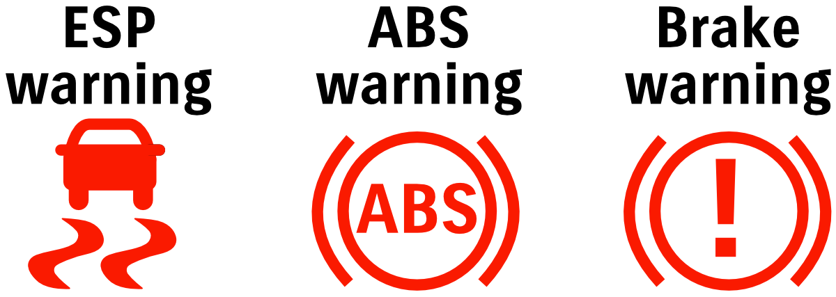
| Code | ESP warning | ABS warning | Brake warning | Code name | Conditions | Troubleshooting |
|---|---|---|---|---|---|---|
| C1016 | On | Off | Off | Brake light switch circuit performance | * Brake light switch on longer than threshold with vehicle speed higher than treshold; * Brake light switch not triggered despite brake master cylinder pressure sensed beyond threshold. | Check brake light switch wiring |
| C1021 | On | On | Off | Right front wheel speed sensor voltage | Incorrect voltage on wheel speed sensor recorded | * Check wheel speed sensor wiring * Clean off sensor as metal dust might interefere with its signal |
| C1022 | On | On | Off | Right front wheel speed sensor value | Abnormal wheel speed signal detected | * Check wheel speed sensor wiring * Clean off sensor as metal dust might interefere with its signal |
| C1023 | On | Off | Off | Yaw rate sensor performance/range | * Yaw rate signal out of range * Yaw rate sensor higher than maximum threshold | Check mounting of ABS/ESP module/pump in engine bay; recalibrate ESP system; replace ESP system with known good module and recode. |
| C1024 | On | Off | Off | Steering angle sensor range/performance | * Internal defect in steering angle sensor * Steering angle sensor signal out of range * Steering angle does not change although vehicle is turning right or left | * Clock spring * Wiring harness from steering column * Combination headlight/turn signal light * Wheel alignment (especially drag link adjustment) and steering centre – steering wheel should turn equal amounts left and right off centre |
| C1025 | On | On | Off | Left front wheel speed sensor voltage | Incorrect voltage on wheel speed sensor recorded | * Check wheel speed sensor wiring * Clean off sensor as metal dust might interefere with its signal |
| C1026 | On | On | Off | Left front wheel speed sensor value | Abnormal wheel speed signal detected | * Check wheel speed sensor wiring * Clean off sensor as metal dust might interefere with its signal |
| C1027 | Off | Off | Off | ESP disable switch failure | ESP switch turned on for longer than threshold | * Dash switch and/or wiring |
| C1028 | On | Off | Off | Master cylinder pressure sensor range | Brake master cylinder pressure is out of range/stuck/brake booster pressure out of range | * Wiring to brake master cylinder sensor * Pressure sensor * Brake pedal position |
| C102B | On | Off | Off | Brake booster pressure signal stuck | Brake booster pressure signal is either stuck at one value or out of threshold range | * Wiring to brake master cylinder sensor * Pressure sensor * Brake pedal position |
| C1031 | On | On | On | Right rear wheel speed sensor voltage | Incorrect voltage on wheel speed sensor recorded | * Check wheel speed sensor wiring * Clean off sensor as metal dust might interefere with its signal * May result from issues relating to rear wheel bearing on right side |
| C1032 | On | On | On | Right rear wheel speed sensor value | Abnormal wheel speed signal detected | * Check wheel speed sensor wiring * Clean off sensor as metal dust might interefere with its signal * May result from issues relating to rear wheel bearing on right side |
| C1034 | On | On | Off | Yaw sensor power supply failure | Voltage for yaw sensor too low with ignition switched on | |
| C1035 | On | On | On | Left rear wheel speed sensor voltage | Incorrect voltage on wheel speed sensor recorded | * Check wheel speed sensor wiring * Clean off sensor as metal dust might interefere with its signal * May result from issues relating to rear wheel bearing on left side |
| C1036 | On | On | On | Left rear wheel speed sensor value | Abnormal wheel speed signal detected | * Check wheel speed sensor wiring * Clean off sensor as metal dust might interefere with its signal * May result from issues relating to rear wheel bearing on left side |
| C1037 | On | Off | Off | Steering angle sensor power supply low voltage | Steering angle sensor power supply voltage is lower than threshold | |
| C1038 | On | Off | Off | Steering angle sensor detects CAN failure | Invalid CAN data received by steering angle sensor from ABS/ESP module | |
| C1039 | On | On | Off | Yaw rate sensor internal failure | Internal failure detected in yaw rate sensor | |
| C1041 | On | On | On | Right front inlet solenoid valve circuit correlation | Electrical failure of solenoid | |
| C1042 | On | On | On | Right front outlet solenoid valve circuit correlation | Electrical failure of solenoid | |
| C1043 | On | On | On | Cut solenoid #1 valve circuit correlation | Electrical failure of solenoid | |
| C1044 | On | On | On | Cut solenoid #2 valve circuit correlation | Electrical failure of solenoid | |
| C1045 | On | On | On | Left front inlet solenoid valve circuit correlation | Electrical failure of solenoid | |
| C1046 | On | On | On | Left front outlet solenoid valve circuit correlation | Electrical failure of solenoid | |
| C104B | On | Off | Off | Reverse light switch malfunction | Reverse signal is out of range / reverse detected when car driving forwards | * Wiring to transmission/gearbox * Shorts from water or other issues in rear taillight and/or taillight wiring |
| C104D | Off | Off | Off | Hill descent switch failure | Hill descent switch turned on for longer than threshold | * Dash switch and/or wiring |
| C1051 | On | On | On | Right rear inlet solenoid valve circuit correlation | Electrical failure of solenoid | |
| C1052 | On | On | On | Right rear outlet solenoid valve circuit correlation | Electrical failure of solenoid | |
| C1055 | On | On | On | Left rear inlet solenoid valve circuit correlation | Electrical failure of solenoid | |
| C1056 | On | On | On | Left rear outlet solenoid valve circuit correlation | Electrical failure of solenoid | |
| C1057 | On | On | On | ESP power supply voltage | Power supply voltage is too high or too low | |
| C1061 | On | On | On | Pump motor circuit performance | * When pump motor is activated, a malfunction in pump motor is detected. * Power supply from module to pump motor and pump motor relay monitor data disagree. * Pump motor power supply voltage is out of specified range. | |
| C1063 | On | On | On | Solenoid valve circuit performance | Solenoid valve power supply and output disagree (one is on with the other off) | |
| C1065 | Off | Off | Off | Brake light circuit failure | Input voltage to brake relay and brake light status disagree for more than threshold time | * Shorts from water or other issues in rear taillight and/or taillight wiring |
| C1068 | On | On | Off | Yaw rate sensor circuit performance | Yaw rate sensor out of range value / value freezing / internal defect detected | |
| C1069 | On | Off | Off | Steering angle sensor failure | Unconfirmed failure detected in steering angle sensor | |
| C1071 | On | On | On | ESP module failure | Internal failure detected in ESP module | |
| C1074 | On | On | Off | Yaw rate calibration | Yaw rate sensor calibration not completed | |
| C1075 | On | Off | Off | Steering angle sensor calibration | Steering angle sensor calibration not completed | |
| C107A | On | Off | Off | Yaw rate assembly calibration | Yaw rate assembly calibration not completed | |
| C1090 | On | Off | Off | ECU received invalid CAN data from ESP module | Invalid data has been transmitted from ESP module to ECU | |
| C1091 | On | Off | Off | CAN invalid data from ECU | ESP module has received invalid CAN data from ECU / relevant DTC from ECU has been detected | |
| C1092 | On | Off | Off | CAN invalid data from TCM | ESP module has received invalid CAN data from TCM / relevant DTC from TCM has been detected | |
| C1094 | On | Off | Off | Torque request reject status | ESP module received invalid CAN from ECU for engine torque control | |
| C10A7 | Off | Off | Off | Invalid data from autonomous braking module | ESP module received invalid CAN data from autonomous braking module (counter value) | |
| C10A8 | Off | Off | Off | Invalid data from autonomous braking module | ESP module received invalid CAN data from autonomous braking module (sum) | |
| C10A9 | On | Off | Off | Invalid autonomous brake request from module | ESP module received autonomous braking request for longer than threshold | |
| U0073 U0100 U0101 U0114 U0126 U0140 U1093 | On (except U1093) | Off (all) | Off (all) | Lost communications | 073: Can’t transmit CAN 100: ECU 101: TCM 114: 4WD 126: Steering angle sensor 140: BCM 1093: Autonomous braking |
ESP fail-safe modes
There are a number of fail-safe states for the ESP system which are also useful to understand with error codes you might have. For instance: error C1016 (brake light switch performance) still has ABS and electronic brake distribution (EBD) active, but traction control, stability control, autonomous braking and hill descent control are all disabled until a) system is no longer in the error state and b) the car has been switched off and back on again.
Where a ‘road test’ is required to cancel a fail-safe state, this is to take the vehicle through a range of parameters. In general it requires:
- Drive for > 40 km/h for > 2 minutes
- Turn right and left at speeds > 10 km/h for over a second, with the steering wheel turning > 45º each way
- Drive at 60 km/h for > 3 s
- Stop the vehicle from a speed > 60 km/h
| Code | Anti-lock brakes | Electronic brake distribution | Traction / stability control | Autonomous braking | Hill descent | Fail-safe cancellation |
|---|---|---|---|---|---|---|
| C1016 | Enabled | Enabled | Disabled | Disabled | Disabled | System tests ok, ignition cycled |
| C1021 | Disabled | Enabled | Disabled | Disabled | Disabled | System tests ok, ignition cycled |
| C1022 | Disabled | Enabled | Disabled | Disabled | Disabled | System tests ok, road test completed ok, ignition cycled |
| C1023 | Enabled | Enabled | Disabled | Disabled | Disabled | System tests ok, road test completed ok, ignition cycled |
| C1024 | Enabled | Enabled | Disabled | Disabled | Disabled | System tests ok, ignition cycled |
| C1025 | Disabled | Enabled | Disabled | Disabled | Disabled | System tests ok, ignition cycled |
| C1026 | Disabled | Enabled | Disabled | Disabled | Disabled | System tests ok, road test completed ok, ignition cycled |
| C1027 | Enabled | Enabled | Enabled | Enabled | Enabled | System tests ok, ignition cycled |
| C1028 | Enabled | Enabled | Disabled | Disabled | Disabled | System tests ok, road test completed ok, ignition cycled |
| C102B | Enabled | Enabled | Disabled | Disabled | Disabled | System tests ok, ignition cycled |
| C1031 | Enabled | Enabled | Enabled | Enabled | Enabled | System tests ok, ignition cycled |
| C1032 | Enabled | Enabled | Enabled | Enabled | Enabled | System tests ok, road test completed ok, ignition cycled |
| C1034 | Disabled | Enabled | Disabled | Disabled | Disabled | System tests ok, ignition cycled |
| C1035 | Disabled | Disabled | Disabled | Disabled | Disabled | System tests ok, ignition cycled +/- road test |
| C1036 | Disabled | Disabled | Disabled | Disabled | Disabled | System tests ok, ignition cycled +/- road test |
| C1037 | Enabled | Enabled | Disabled | Disabled | Disabled | System tests ok Ignition off |
| C1038 | Enabled | Enabled | Disabled | Disabled | Disabled | Ignition off |
| C1039 | Disabled | Enabled | Disabled | Disabled | Disabled | System tests ok, road test completed ok, ignition cycled |
| C1041 | Disabled | Disabled | Disabled | Disabled | Disabled | System tests ok, road test completed ok, ignition cycled |
| C1042 | Disabled | Disabled | Disabled | Disabled | Disabled | System tests ok, road test completed ok, ignition cycled |
| C1043 | Disabled | Disabled | Disabled | Disabled | Disabled | System tests ok, road test completed ok, ignition cycled |
| C1044 | Disabled | Disabled | Disabled | Disabled | Disabled | System tests ok, road test completed ok, ignition cycled |
| C1045 | Disabled | Disabled | Disabled | Disabled | Disabled | System tests ok, road test completed ok, ignition cycled |
| C1046 | Disabled | Disabled | Disabled | Disabled | Disabled | System tests ok, road test completed ok, ignition cycled |
| C104B | Enabled | Enabled | Disabled | Disabled | Disabled | System tests ok |
| C104D | Enabled | Enabled | Enabled | Enabled | Disabled | System tests ok, ignition cycled |
| C1051 | Disabled | Disabled | Disabled | Disabled | Disabled | System tests ok, road test completed ok, ignition cycled |
| C1052 | Disabled | Disabled | Disabled | Disabled | Disabled | System tests ok, road test completed ok, ignition cycled |
| C1055 | Disabled | Disabled | Disabled | Disabled | Disabled | System tests ok, road test completed ok, ignition cycled |
| C1056 | Disabled | Disabled | Disabled | Disabled | Disabled | System tests ok, road test completed ok, ignition cycled |
| C1057 | Disabled | Disabled | Disabled | Disabled | Disabled | System tests ok, road test completed ok, ignition cycled |
| C1061 | Disabled | Disabled | Disabled | Disabled | Disabled | System tests ok, road test completed ok, ignition cycled |
| C1063 | Disabled | Disabled | Disabled | Disabled | Disabled | System tests ok, road test completed ok, ignition cycled |
| C1065 | Disabled | Enabled | Enabled | Disabled | Disabled | Ignition off |
| C1068 | Disabled | Enabled | Disabled | Disabled | Disabled | System tests ok, road test completed ok, ignition cycled |
| C1069 | Enabled | Enabled | Disabled | Disabled | Disabled | System tests ok, ignition off |
| C1071 | Disabled | Disabled | Disabled | Disabled | Disabled | Ignition off |
| C1074 | Disabled | Enabled | Disabled | Disabled | Disabled | Once yaw rate sensor is calibrated |
| C1075 | Enabled | Enabled | Disabled | Disabled | Disabled | Once steering angle sensor is calibrated |
| C107A | Enabled | Enabled | Disabled | Disabled | Disabled | Once yaw rate sensor is calibrated |
| C1090 | Enabled | Enabled | Disabled | Disabled | Disabled | Ignition off |
| C1091 | Enabled | Enabled | Disabled | Disabled | Disabled | Ignition off |
| C1092 | Enabled | Enabled | Disabled | Disabled | Disabled | Ignition off |
| C1094 | Enabled | Enabled | Disabled | Disabled | Disabled | System tests ok, ignition cycled |
| C10A7 | Enabled | Enabled | Enabled | Disabled | Enabled | Ignition off |
| C10A8 | Enabled | Enabled | Enabled | Disabled | Enabled | Ignition off |
| C10A9 | Enabled | Enabled | Enabled | Disabled | Enabled | Ignition off |
| U0073 U0100 U0101 U0114 U0126 U0140 U1093 | Enabled | Enabled | Enabled (except 1093) | Disabled | Disabled (except 1093) | 0073: System tests ok, ignition cycled Others: Ignition off |
Autonomous braking
Note formally this is its own module, not under the ABS/ESP module, and is referred to as the ‘Dual sensor brake system’ or DSBS module.
| Code | Meaning | Troubleshooting hints |
|---|---|---|
| C1680 C1685 C1686 C1688 C1689 | C1680: Control module performance/internal failure 85: Internal temperature high 86: Control mismatch (brake request from ESP & DSBS disagree) 88: Operation time (autonomous braking commanded 3 or more times per detection cycle) 89: Internal temperature low | These all potentially indicate failure in the DSBS module, depending on other DTCs set in other modules |
| C1681 | Verification between instrument cluster and DSBS module mismatch | Coding mismatch between cluster and DSBS: potentially as one has been replaced and not coded to the vehicle. This will only be a live DTC and will not stored |
| C1687 C16A0 | C1687: Engine torque control request disabled / not received at ECU from DSBS A0: CAN data invalid from ECU | Potentially errors in wiring to ECU circuit to ECU or to DSBS; reset and recheck as these might be the result of other DTCs in the system |
| C1690 C16C1 | C1690: Sensor not aligned C16C1: Camera misaligned | C1690 is a live DTC only; align sensor in this case. C16C1: Realign sensor, clear DTCs, recheck |
| C16A1 | Invalid CAN data from TCM | Check wiring to TCM; replace TCM if required |
| C16A2 | Invalid CAN from BCM | Check wiring to BCM; replace BCM if required |
| C16A3 | Invalid CAN from ABS/ESP module | Check wiring to ABS/ESP module Might be the result of wheel speed sensor wiring broken or sensor failure; can also receive if pulling ABS fuse to remove traction control offroad (and is stored as a historic code) |
| C16A8 | Communication error from DSBS to ABS/ESP module | Error detected in communication/commands to ABS module. Check ABS module wiring; may require replacement of DSBS module if wiring is correct |
| C16A9 | Invalid CAN from power steering module | Check wiring to power steering module; replace module if required |
| C16C0 | Control temporary inhibition Detected for the following: * Power supply voltage too high or low; * Poor visibility of camera or laser; * Invalid CAN data received from turn/light switch; * Invalid CAN from ABS/ESP module; or * Temperature of DSBS module too high | Check power supply wiring to the DSBS module, and check wiring and performance of ABS/ESP module and turn/light switch |
| C16C8 | DSBS off switch pressed for too long | Check wiring to DSBS off switch on dashboard |
| C16C9 | Lane departure off switch pressed for too long | Check wiring to lane departure off switch on dashboard |
| U0073 U0100 U0101 U0121 U0126 U0131 U0140 U0155 | Lost CAN signal U0073: ECU cannot transmit/receive on CAN U0100: DSBS <-> ECU U0101: DSBS <-> TCM U0121: DSBS <-> ABS/ESP module U0126: DSBS <-> steering angle sensor U0131: DSBS <-> power steering U0140: DSBS <-> BCM U0155: DSBS <-> gauges | Check CAN wiring through each module to verify no errors in the network daisy-chain |
DSBS warning error meaning/troubleshooting
There are a number of states for the DSBS warning system, including the 3 states of intervention. These states, along with states resulting from errors in the system, are displayed on the central display LCD screen in the gauge cluster.
Collision warning
The following conditions trigger this:
- Your speed is between 15 and 140 km/h for a stopped vehicle ahead; or,
- Your speed is between 15 and 60 km/h for a pedestrian in front of the vehicle; or,
- Relative speed between you and a vehicle or pedestrian is > 15 km/h,
then this warning will sound a buzzer and display the following warning in the central display of the gauge cluster:
Note that this collision warning is just that: a warning. It does not engage the brakes or take any further action unless further conditions are met.
Brake assist
If the following conditions are met:
- Your speed is between 15 and 80 km/h for a stopped vehicle ahead; or,
- Your speed is between 15 and 60 km/h for a pedestrian in front of the vehicle; or,
- Relative speed between you and a vehicle or pedestrian is > 15 km/h; and,
- The brake pressure is insufficient to slow the vehicle to a stop in time before a collision will occur,
then the same graphic as shown above and buzzer will alert, but the car will command the ABS/ESP unit to add brake line pressure to assist the car in slowing down.
Autonomous braking
The autonomous braking is the most severe of the interventions the car’s collision avoidance system can take. This is activated if the following requirements are met:
- Your speed is between 5 and 100 km/h for a stopped vehicle ahead; or
- Your speed is between 15 and 60 km/h for a pedestrian in front of the vehicle; or
- Relative speed between you and a vehicle or pedestrian is > 5 km/h; and,
- A collision will occur,
then the car will automatically apply the brakes along with sounding the warning buzzer and flashing the warning. Note that the speed differential part is the key here: this system will brake you even if you are initially doing > 100 km/h despite the first condition.
Ultimately a lot of people never get to the autonomous braking phase; when they talk about getting phantom collision warnings they are generally only getting the first warning (red warning on the gauge cluster central display and the buzzer sounding).
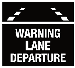
Lane departure
If the camera system detects a lane departure, the system will command a light steering wheel shake and display a lane departure warning in the central LCD display in the gauge cluster. This warning will flash whatever lane is being departed from i.e. if you drift to the left out of a lane then the left lane marking will flash and the opposite for right departure from a lane.
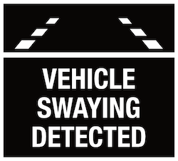
Vehicle swaying
In addition to lane departure, it is possible for the Jimny to detect swaying within a lane and take corrective action to limit this swaying. For this warning the lane edge symbols will blink alternatively so left and then right and back to left again.
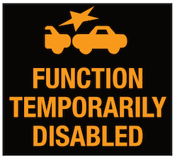
Temporary error disabling DSBS
One potential error that you might see is the ‘function temporary disabled’ with an orange/yellow text rather than white or red. This is used for some temporary issues like some types of CAN connectivity or disagreement between sensors. Generally this type of error is one that will reset either on vehicle startup or after some time as the temporary error sorts itself out e.g. a sensor to another module comes back online or starts to work correctly.
System malfunction
This is really the catch-all error and gives you an orange “system warning” error on the central LCD panel on the gauge cluster.
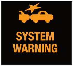
This warning is only used in the case of other less specific warnings and generally indicates a more serious fault than just a temporary disabling of the system.
Some basic diagnostic information is available just based on when this warning appears:
- If this comes on within 5-10 seconds of starting the car then it is likely a fault within the module, and further investigation is required usually via onboard diagnostic checks to rule out other causes.
- If it comes on upon ignition on before starting then it is more likely a power issue to the module e.g. blown fuse.
- Finally, if this error comes on when driving then it is more than likely related to CAN communication e.g. receiving incorrect data from some other module. This could relate to an issue with that other module, or, it could be as simple as some other sensor disagreement e.g. shorting out reverse light signal when you brake due to water in the tail lights connector
Camera visibility
This is the most commonly seen error and people often ask what’s wrong with their car when they see this error.
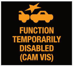
As the name implies, this error relates to the visibility of the camera. Dirt on the windscreen in front of the camera, heavy rain, mist on the inside of the windscreen/camera module, or even opening your bonnet and starting your car will give you this error.
Note that in some markets this and the following error may only be indicated as “Function temporary disabled” error, not specific to the issue at hand. This is why people often default to any dash warning about the crash system being something where cleaning the windscreen will help… it’s not always that simple, especially for module failures or sensor issues in other modules.
DSBS internal temperature too high
The final type of error is the error relating to the camera system overheating.
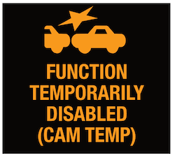
This, as the name implies, is most likely to happen on hot days or when parking in the sun. Driving with the air conditioning on and cooling the cabin often appears to be sufficient to clear this error.
Note that just as per cam visibility errors, this will potentially be only warned as “function temporarily disabled” in some markets. If the windscreen is clear and there’s nothing obstructing the camera visibility and the car is either warm inside or has been parked in the sun for a while then this is the most likely cause.
Power steering
| Code | Meaning | Troubleshooting hints |
|---|---|---|
| C1111 C1113 C1114 C1115 | Torque sensor errors: C1111: Main sensor circuit error C1113: Signal difference main and secondary sensors C1114: Power supply circuit malfunction C1115: Secondary sensor circuit error | * Check wiring to torque sensor * Check power supply to torque sensor * Check ground to torque sensor * Voltage differences expected at pins at torque sensor connector: – Neutral position o TS3-TS4: 2.5 V o TS3-TS5: 2.5 V – Turned fully right o TS3-TS4: 1.2 V o TS3-TS5: 3.8V – Turned fully left o TS3-TS4: 3.8 V o TS3-TS5: 1.2 V Voltages should change linearly as turning; the values an also be seen to linearly change using a scantool with live monitoring. |
| C1141 C1142 C1143 C1145 | Power steering motor errors: C1141: Input voltage too high C1142: Current measurement error: target to actual difference more than 10 A C1143: Overcurrent (> 45 A) C1145: Current circuit error: target motor current higher than measured | Check power steering motor wiring, input voltage, and circuits of motor; replace P/S module for no other issues found |
| C1152 C1154 | Fail safe relay errors: 52: Voltage measured at relay > 5.5 V but relay off is commanded 54: Voltage measured at relay < 4 V but relay on is commanded | Check power and ground to power steering module |
| C1153 | Power supply too high (unspecified voltage) or too low (< 9 V) | Check power supply to power steering module and check resistance of power supply circuit |
| C1155 C1157 | Malfunctions 55: Module internal failure 57: Motor relay malfunction | Check power and ground to power steering module Replace power steering module if persists |
| C1160 | Assist data not set in P/S module | Replace power steering module |
| C1161 C1162 C1166 | CAN error: invalid data 61: Invalid road speed data from ECU 62: Invalid engine speed data from ECU 66: Invalid road speed reliability data from ECU | 61/66: Engine code P0500 troubleshooting 62: Engine code P0335 troubleshooting |
| C1163 | Invalid steering angle sensor data | Use steering angle sensor code C1038 troubleshooting |
| C116A | Steering angle sensor calibration incomplete | Calibrate steering angle sensor |
| U0073 U0100 U0121 U0126 U0155 U1093 | Lost CAN U0073: PSM cannot transmit/receive on CAN U0100: PSM <-> ECU U0121: PSM <-> ABS/ESP module U0126: PSM <-> steering angle sensor U0155: PSM <-> gauges U1093: PSM <-> autonomous braking | Check CAN network central gateway and CAN wiring |
A/C system: automatic
Note: If B150A, B150C, B1519 and/or B151B indicated together then sensor ground is open circuit
| Code | Meaning | Fail-safe assumptions | Troubleshooting |
|---|---|---|---|
| B1508 | Cabin temperature circuit > 4.9 V | BCM assumes cabin is 25 ºC | * Check cabin temperature sensor wiring * Beige and red wire at cabin temp sensor pins shorted together should give scantool reading cabin temp < -40 ºC: if it doesn’t then replace cabin temp sensor * Short wires at BCM G05-06 and G04-22: if this doesn’t give < -40 ºC cabin temp then replace BCM or dash wiring harness |
| B1509 | Cabin temperature circuit < 0.1 V | BCM assumes cabin is 25 ºC | If cabin temp sensor disconnected doesn’t give temperature > 87.5 ºC on scantool then replace cabin temp sensor; If it does and beige wire BCM G05-06 is not shorted to ground then replace BCM; otherwise dash wiring harness |
| B150A | Sunload sensor high | Assumes vehicle is in sunlight | Check with 100 W halogen light bulb/20W LED shining from 0.1 m onto sunload sensor: should give ~140 W/m^2 on scantool. Otherwise replace sunload sensor, or BCM, or dash wiring harness. Note if this code is thrown with sunload sensor not lit then this does not indicate a malfunction: it requires light. |
| B150B | Sunload sensor low | Assumes vehicle is in sunlight | Disconnect sunload sensor: if scantool doesn’t report sunload > 1275 W/m^2 then replace sunload sensor. If it does then check sensor circuit 0-1V with ignition on; if voltage is within range then replace BCM, otherwise replace wiring harness. |
| B150C B1519 B151B | Circuit high in: 150C: Temp control actuator 1519: Air flow control actuator 151B: Air intake control actuator | N/A | Check wiring and voltages on sensor pins |
| B150D B151A B151C | Circuit low in: 150D: Temp control actuator 151A: Air flow control actuator 151C: Air intake control actuator | N/A | Check wiring and voltages on sensor pins |
| B1513 B1514 B1531 | Circuit malfunction in: 1513: Temp control actuator 1514: Air flow control actuator 1531: Air intake control actuator For all: difference between target and actual opening is beyond threshold | N/A | Check wiring and voltages on sensor pins |
| B1141 B1142 | Not listed (BCM error) | Outside air temperature is 20 ºC | |
| B1145 B1146 | Not listed (BCM error) | Evaporator temperature is 0 ºC | |
| B1546 | Refrigerant pressure error | N/A | Check refrigerant charge levels; wiring harness in engine bay; sensor wiring for signal, ground and power |
| B1549 / U2005 | LIN errors: B1549: Invalid data from BCM to HVAC panel U2005: Invalid data from HVAC panel to BCM | Temperature selector: 25 °C Mode: defrost Air intake: fresh Blower fan speed: automatic A/C: on Rear demister: off | Check panel wiring/circuits |
| B1563 | Invalid refrigerant pressure data from ECU | N/A | Check ECU wiring and to refrigerant sensor, assuming U0073 or U0100 are not present, otherwise troubleshoot lost CAN |
| U0073 | CAN comms bus off | N/A | Check CAN network central gateway and CAN wiring |
| U0100 | Lost CAN (to ECU) | Coolant temperature: 80 ºC Vehicle speed: 255 km/h | Check CAN network central gateway and CAN wiring |
Air bag / restraint system
I have based this off codes for the 8/10 channel system as per Australia and high spec 4 seaters across the world. Commercial versions and/or versions with fewer airbags and sensors might throw different codes though potentially the meaning to a code will be similar.
Some official documentation of the Jimny’s airbag module calls it the “sensing and diagnostic module” or SDM. Although I call it the airbag module, it does also handle things such as the seatbelt pretensioner system and thus is probably better/more formally referred to as the supplementary restraint system module or SRS module. (I’m partly adding this text for SEO work so people will find this page no matter what term they use).
Note I have included some codes which are common to the 8/10 channel system but not applicable for Australia e.g. some markets have a passenger airbag disabling switch where required. I have fortunately received information from UK owners to help guide my writeup of these codes, but I cannot check any of them against my car.
A common source of errors related to the airbag/SRS arise from either:
- Removing seatbelts such as rear seatbelts, as their pretensioners are no longer detected; or
- Removing front seats from the car and driving around with a front seat removed, or, damaging seat wiring e.g. with camping gear hitting the wiring under the seats.
| Code | Meaning | Troubleshooting hints |
|---|---|---|
| B1002-00 | Intermittent connection of airbag module | Check the airbag module wiring and associated harness |
| B1003-04 | Airbag module internal failure | Replace airbag module, recode to vehicle and retest |
| B1004-17 B1004-18 | Power supply voltage too high (-17) or too low (-18) | Check wiring to airbag module and also check performance of charging system If this occurs after a flat battery, reset DTCs and it should remain off once a fresh battery is installed or charging system performance is rectified |
| B1007-01 B1008-01 | Passenger airbag light circuit is off, grounded or shorted to power for: B1007-01: Off light B1008-01: On light | Check wiring to hazard warning switch, airbag warning light and to airbag module |
| B1009-1A B1009-1B B1009-1E | Passenger airbag disable switch shorted to ground (-1A), shorted to power or is open circuit (-1B), or malfunctioning (-1E) | Check wiring to airbag disable switch, airbag warning light and to airbag module |
| B1032-00 B1033-00 B1034-00 B1035-00 B1036-00 B1037-00 B1039-00 | Airbag deployment recorded, code relates to which airbag. B1032-00: Front 33: Drivers side (seat) 34: Passengers side (seat) 36: Drivers side (curtain) 37: Passengers side (curtain) B1035-00: Seatbelt pretensioner deployment, front 39: Seatbelt pretensioner deployment, rear | These codes cannot be cleared from the airbag module, and the module itself must be replaced If these codes are recorded without airbag deployment then there will be wiring faults or issues with the inflators/initators that must be remedied before replacing the airbag module. |
| B1060-14 B1060-15 B1060-1A B1060-1B | First stage drivers side airbag circuit shorted to ground (-14), power supply (-15), low resistance (-1A), or high resistance (-1B) | Check: * Drivers side inflator wiring and inflator * Clockspring * Wiring to airbag module |
| B1062-14 B1062-15 B1062-1A B1062-1B | First stage passengers side airbag circuit shorted to ground (-14), power supply (-15), low resistance (-1A), or high resistance (-1B) | Check: * Passengers side inflator wiring and inflator * Wiring to airbag module |
| B1064-14 B1064-15 B1064-1A B1064-1B | Drivers side front seatbelt pretensioner: B1064-14: shorted to ground -15: shorted to power -1A: low resistance on circuit -1B: high resistance on circuit | |
| B1065-14 B1065-15 B1065-1A B1065-1B | Passengers side front seatbelt pretensioner: B1065-14: shorted to ground -15: shorted to power -1A: low resistance on circuit -1B: high resistance on circuit | |
| B1068-14 B1068-15 B1068-1A B1068-1B | Drivers side airbag circuit: B1068-14: shorted to ground -15: shorted to power -1A: low resistance on circuit -1B: high resistance on circuit | |
| B1069-14 B1069-15 B1069-1A B1069-1B | Passengers side airbag circuit: B1069-14: shorted to ground -15: shorted to power -1A: low resistance on circuit -1B: high resistance on circuit | |
| B106C-14 B106C-15 B106C-1A B106C-1B | Drivers side curtain airbag circuit: B106C-14: shorted to ground -15: shorted to power -1A: low resistance on circuit -1B: high resistance on circuit | |
| B106D-14 B106D-15 B106D-1A B106D-1B | Passengers side curtain airbag circuit: B106D-14: shorted to ground -15: shorted to power -1A: low resistance on circuit -1B: high resistance on circuit | |
| B1071-14 B1071-15 B1071-1A B1071-1B | Drivers side rear seatbelt pretensioner: B1071-14: shorted to ground -15: shorted to power -1A: low resistance on circuit -1B: high resistance on circuit | |
| B1072-14 B1072-15 B1072-1A B1072-1B | Passengers side rear seatbelt pretensioner: B1072-14: shorted to ground -15: shorted to power -1A: low resistance on circuit -1B: high resistance on circuit | |
| B1090-01 B1090-95 | Driver forward impact sensor: B1090-01: no response -95: comms data inconsistent | |
| B1090-14 B1090-15 B1090-87 | Driver forward impact sensor: B1090-14: shorted to ground -15: open circuit -87: comms data invalid | |
| B1093-01 B1093-14 B1093-15 B1093-87 B1093-95 | Side impact sensor (drivers side front): B1093-01: No response -14: shorted to ground -15: open circuit -87: comms data invalid -95: communicated inconsistent ID code | |
| B1094-01 B1094-14 B1094-15 B1094-87 B1094-95 | Side impact sensor (passengers side front): B1093-01: No response -14: shorted to ground -15: open circuit -87: comms data invalid -95: communicated inconsistent ID code | |
| B1095-01 B1095-14 B1095-15 B1095-87 B1095-95 | Side impact sensor (drivers side rear): B1095-01: No response -14: shorted to ground -15: open circuit -87: comms data invalid -95: communicated inconsistent ID code | |
| B1096-01 B1096-14 B1096-15 B1096-87 B1096-95 | Side impact sensor (passengers side rear): B1095-01: No response -14: shorted to ground -15: open circuit -87: comms data invalid -95: communicated inconsistent ID code | |
| U0073-88 | Lost CAN signal | Check CAN wiring through each module to verify no errors in the network daisy-chain |
Lighting / headlight levelling
| Code | Meaning | Troubleshooting hints |
|---|---|---|
| B1950 | Levelling module internal failure | Replace module |
| B1951 | Module power supply voltage malfunction (> 16.4 V for > 10 s or < 9.3 V for > 10 s) | Can arise after a flat battery/failing charging system. Check: * Wiring to headlight levelling module * Charging system |
| B1956 | Rear height sensor error Signal > 4.75 V for > 10 s or < 0.25 V for > 10 s Sensor power supply > 6.25 V for > 10 s or < 4.45 V for > 10 s | Can arise after a flat battery/failing charging system. Check: * Wiring to headlight levelling sensor and module * Charging system |
| B1957 B1958 | Headlight control circuit open or > 1.5 V: B1957: right side B1958: left side | Check wiring to headlights |
| B1967 | Lack of ride height sensor initial setting | First: Initalise headlight levelling system through diagnostic tool. If problem persists then check for intermittent problem or failure of headlight levelling module. |
| B1970 | Wheel speed sensor malfunction | Indicates headlight levelling module is not correctly receiving vehicle speed on CAN. Check wheel speed sensors, ABS/ESP module, wiring from wheel speed sensors and to/from headlight levelling module |
| B1A80 | Lighting and turn signal internal failure | Replace lighting and turn signal switch if problem persists after clearing DTC |
| B1A81 B1A82 | Battery voltage either too low (B1A81) or too high (B1A82) | Can occur after flat battery or charging system failures. Check: * Power supply circuit from IG1 SIG relay and BCM to the lighting switch * Wiring harness to lighting switch * Replace lighting and turn signal switch if no other wiring/power issues detected |
| B1AA0 B1AA1 B1AA2 B1AA3 B1AA4 | Switch errors: B1AA0: auto and switch and head switch are ON at same time B1AA1: rear fog light switch stuck on B1AA2: Passing switch stuck on B1AA3: Turn signal L and R both on at same time B1AA4: Dimmer and passing switch both ON simultaneously | Lighting and turn switch requires replacement |
| B1AB0 | Invalid CAN data from instrument panel display module | Troubleshoot other DTCs detected with this |
| B1AB1 | Invalid CAN data from ABS/ESP module | Troubleshoot other DTCs detected with this |
| U0073 U0100 U0121 U0140 U0155 | Lost CAN signal U0073: Levelling module cannot transmit/receive on CAN U0100: Levelling module <-> ECU U0121: Levelling module <-> ABS/ESP module U0140: Levelling module <-> BCM U0155: Levelling module <-> gauges | Check CAN wiring through each module to verify no errors in the network daisy-chain |
Gauges & controls
| Code | Meaning | Troubleshooting hints |
|---|---|---|
| B1810 B1811 | Fuel level sender B1810: open circuit 11: short circuit | Fuel level sender and its wiring; gauge cluster |
| B1820 | Gauge cluster internal EEPROM error | Replace gauge cluster |
| B1840 | Vehicle speed invalid data received from ECU | Check: * Wheel speed sensors and their wiring * ESP control module * ECU * Gauge cluster and its wiring |
| B1841 | Received invalid outside air temperature data from BCM | Check: * Outside air temperature and its wiring * Body control module * Gauge cluster |
| B1842 | Received invalid fuel consumption data from ECU | Check: * ECU wiring * Other stored DTCs and troubleshoot those |
| B1952 | Windshield washer motor supply voltage low | This code can appear after a flat battery or incorrectly performing charging system Check: * Battery and charging system * Wiring to windshield washer motors * Headlight auto levelling module (this also controls headlight washing) |
| P0575 | Cruise control input circuit | Signal voltage from cruise control switch is too high for too low, or switches are sending ON for longer than a threshold time Check: * Cruise control switch wiring and switches * Clockspring * ECU wiring |
| P0649 | Cruise control lamp control circuit | This error means the cruise set/limit lighting signal from gauge cluster disagrees with an ECU command to turn on or off this display Check: * ECU and its wiring * CAN communication circuit especially to gauge cluster and ECU * Gauge cluster may require replacement |
| U0073 U0100 U0101 U0121 U0127 U0140 U0151 U1093 | Lost CAN signal U0073: Gauges cannot transmit/receive on CAN U0100: Gauges <-> ECU U0101: Gauges <-> TCM U0121: Gauges <-> ABS/ESP module U0127: Gauges <-> TPMS module (if fitted) U0140: Gauges <-> BCM U0151: Gauges <-> airbag mdule U1093: ECU <-> autonomous braking | Check CAN wiring through each module to verify no errors in the network daisy-chain |
Body control module
| Code | Meaning | Troubleshooting hints |
|---|---|---|
| B1170 | BCM EEPROM internal error | Replace BCM |
| B1123 | DOME fuse circuit / open | Check: * DOME2 fuse * BCM/junction box wiring * Body control module |
| B1133 | Battery voltage too high (> 16V from DOME2 fuse) | Check: * Charging system * Body control module |
| B1141 B1142 | Outside air temperature circuit B1141: open (> 4.68 V) B1142: shorted to ground | Check: * Outside air temperature circuit wiring * Outside air temperature sensor * BCM |
| B1145 B1146 | A/C evaporator temperature sensor B1145: too high (> 4.85V) B1146 too low (< 0.15V) | Check: * A/C evaporator temperature circuit wiring * A/C evaporator temperature sensor * BCM |
| B1147 B1148 | Auto light sensor B1147: shorted to power (> 4.8V) B1148: shorted to ground (< 0.5V) | Check: * Auto light sensor circuit wiring * Auto light sensor * BCM |
| B1157 | Air bag impact signal input | Check: * Has vehicle been in collision before and BCM codes not cleared? * If no collision, might be error in BCM: replace with known good * Error in airbag module if no error in BCM |
| U0073 U0100 U0101 U0151 U0155 U108B U1093 U2005 | Lost CAN signal | Check CAN wiring through each module to verify no errors in the network daisy-chain |
Immobiliser
| Code | Meaning | Troubleshooting hints |
|---|---|---|
| P1610 | Immobiliser ID not recognised | * Clear DTC and recheck after ignition off for > 1 minute * Register ECU * Check CAN communication to/from ECU * ECU wiring * Replace ECU, if error still detected, replace BCM |
| P1611 | Stored password not recognised | * Clear DTC and recheck after ignition off for > 1 minute * Register ECU * Replace ECU, if error still detected, replace BCM |
| P1622 | EEPROM reading/writing error | * Clear DTC and recheck after ignition off for > 1 minute * Replace ECU if code does not clear |
| P1642 | Immobiliser communication line error | * Check BCM power/ground circuits * Check for CAN communication errors between BCM, ECU * Register ECU and/or keys * Replace ECU, if error still detected, replace BCM |
| P1644 | Immobiliser ID mismatched | * Register ECU and BCM * Replace ECU, if error still detected, replace BCM |
| P1646 | ID code incorrect | * Clear DTC and recheck after ignition off for > 1 minute * Check and troubleshoot CAN communication errors * Register ECU * Replace ECU if unable to clear after all these steps |
| B1168 | Immobiliser password mismatch | * Input immobiliser password, ignition off for > 10 s, then ignition on * If DTC remains then password remains incorrect and obtain correct password |
| B1169 | Registration failure | * Register ECU and BCM * Replace ECU, if error still detected, replace BCM |
| B1173 | Transponder unregistered | Usually this is a key failure * Register key; replace key if problem persists * Troubleshoot CAN communication issues * Replace BCM if persists |
| B1175 | Immobiliser info unregistered | * Register key * Troubleshoot CAN communication issues * Replace BCM if persists |
| B1176 | Specification unrecognised | * Register key * Check if vehicle specification is correctly loaded into BCM and ECU * Troubleshoot CAN communication issues * Replace BCM if persists |
| B1188 | Transponder communication issue | * Register key * Replace BCM if persists |
| B1189 | Immobiliser antenna communication error | * Immobiliser module wiring and wiring around key * Replace immobiliser module * Replace BCM if persists |
| B118A | Battery voltage low (ID code verification) | This can occur after a flat battery or incorrectly performing charging system * Battery and charging system check * BCM power and ground circuits |
CAN communications troubleshooting
There are a couple of DTCs that can occur for the CAN communication specific to the central gateway.
Note that a lot of these lost communications errors can result from flat batteries and cascading failures, so rule out charging system or power issues before throwing out modules or dismantling half the car to check the wiring.
For errors not related to low voltages/times you have had charging issues the key here is the troubleshooting flow for each module when it has lost CAN communication and ensuring you isolate the right things in turn. There’s a lot of options here, which reflects where modules sit in the CAN daisy-chain.
CAN daisy chain diagnosis
All of this diagnosis should be performed with the negative terminal of the battery disconnected to isolate the electrical system. These diagnosis flows depend on which modules are unable to be communicated with.
1. All CAN control modules including central gateway
First, disconnect the central gateway module main connector and check the connections from there to the diagnostic port.
If this does not indicate a fault, reconnect the central gateway connector, disconnect the E connector at the ECU and measure resistance between pins 3 and 9 at the diagnostic connector. These pins should have 114 to 134 Ω resistance, and if they do not have this then replace the central gateway module.
2. All CAN control modules, other than central gateway
Disconnect both the ECU E connector and the central gateway main connector. Check wiring between ECU and central gateway module; if these are ok then measure resistance between pins 20 and 21 on central gateway connector. The resistance should be 114 to 134 Ω. If it is then replace central gateway module; if it isn’t then replace the ECU.
3. Gauges
Disconnect ECU E connector, central gateway main connector and main gauge cluster connector. Check for wiring continuity between all 3 connectors; if ok, check CAN communication lines between central gateway and gauge cluster. Replace cluster if this check is ok.
4. Combination turn and light switch
Disconnect:
- ECU E connector;
- central gateway main connector;
- main gauge cluster connector; and,
- combination turn and light switch.
Check for wiring continuity between all 4 connectors; if ok, check CAN communication lines between central gateway and turn signal switch. Replace turn signal switch if this check is ok.
5. Steering angle sensor
Disconnect:
- ECU E connector;
- central gateway main connector;
- main gauge cluster connector; and,
- steering angle sensor.
Check for wiring continuity between all connectors; if ok, check CAN communication lines between central gateway and steering angle sensor. Replace steering angle sensor and recalibrate if all wiring is ok.
6. Airbag module
Disconnect:
- ECU E connector;
- central gateway main connector;
- main gauge cluster connector; and,
- airbag module.
Check for wiring continuity between all connectors; if ok, check CAN communication lines between central gateway and airbag module. Replace airbag module if all wiring is ok.
Power steering
Disconnect:
- ECU E connector;
- central gateway main connector;
- main gauge cluster connector; and,
- power steering module.
Check for wiring continuity between all connectors; if ok, check CAN communication lines between central gateway and power steering module. Replace module if all wiring is ok.
Autonomous braking
Disconnect:
- ECU E connector;
- central gateway main connector;
- main gauge cluster connector; and,
- DSBS module.
Check for wiring continuity between all connectors; if ok, check CAN communication lines between central gateway and autonomous braking module. Replace DSBS module if all wiring is ok.
ABS & ESP control module
Disconnect:
- ECU E connector;
- central gateway main connector;
- main gauge cluster connector; and,
- ABS module.
Check for wiring continuity between all connectors; if ok, check CAN communication lines between central gateway and ABS module. Replace ABS/ESP module if all wiring is ok.
Headlight leveling
Disconnect:
- ECU E connector;
- central gateway main connector;
- main gauge cluster connector; and,
- Headlight levelling module.
Check for wiring continuity between all connectors; if ok, check CAN communication lines between central gateway and levelling module. Replace levelling module if all wiring is ok.
Body control module
Disconnect:
- ECU E connector;
- central gateway main connector;
- main gauge cluster connector; and,
- BCM E connector.
Check for wiring continuity between all connectors; if ok, check CAN communication lines between central gateway and BCM module. Replace BCM if all wiring is ok.
Transmission control module (A/T models)
Disconnect:
- ECU E connector;
- central gateway main connector;
- main gauge cluster connector; and,
- TCM connector.
Check for wiring continuity between all connectors; if ok, check CAN communication lines between central gateway and TCM. Replace TCM if all wiring is ok.
4WD/vacuum hubs module
Disconnect:
- ECU E connector;
- central gateway main connector;
- main gauge cluster connector; and,
- 4wd module connector.
Check for wiring continuity between all connectors; if ok, check CAN communication lines between central gateway and 4wd module. Replace module if all wiring is ok.