
Suzuki GT250: Electrical work
The electrical side of motorbikes doesn’t hugely interest me but it’s an important thing to get right. Here’s how I sorted out all of the electrical stuff for the Team Ghetto Suzuki GT250.
Wiring diagram
First up, a factory wiring diagram. All of the ones on the net are a bit unreadable, so here’s my redraw of the wiring diagram to make it a bit easier.
That said, that’s the factory setup and I’m not going ahead with too much of that… so, here’s how I sorted it all.
I did manage to purchase a 100% stock unused wiring harness which I’m saving for a rainy day or if I ever want to do this bike as a 100% factory restoration, and it should be useful for troubleshooting too.
Coils
The factory coils are fine, but, the ones that came on the bike when I bought it weren’t ideal, the plug leads were unhappy, and I wanted to switch to a pointless ignition anyway. Best to run lower resistance (3 ohm versus 5 ohm standard) coils doing this, so it seemed like a good idea to buy new and fancy coils.
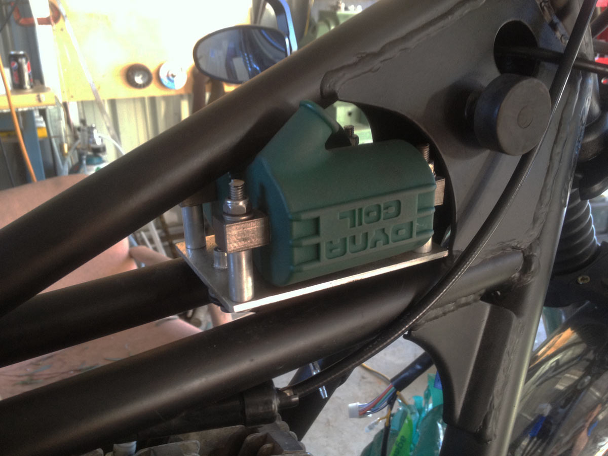
I went with two single-output 3 ohm Dyna coils, finished off with 8mm noise supressing Dyna ignition wires. I mounted them in basically the stock location, but with a bit of additional work to make hide nicely under the tank.
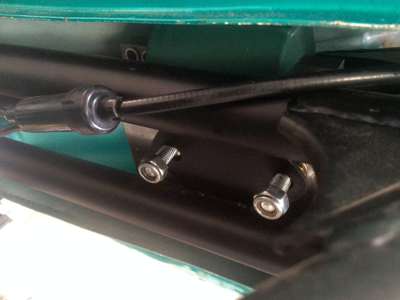
Original plan was to bolt the plate down but it was really hard to do up the coils, too. With that in mind, I ended up putting in nutserts into the plate and you bolt it up from underneath.
First test direction, ended up being a horrid angle for the ignition wires so flipped it around.
Checking the fitment against the tank. Tight, but it fits. Stock coils would have had way more clearance but these work and should be a good upgrade over stock ones.
Spacers are little bits of alloy tubing cut to length. M5 nutserts act to let you bolt the plate to the stock mounting location using bolts done from underneath once you’ve mounted the coils. Tight to get in and out, but it works and that’s what matters.
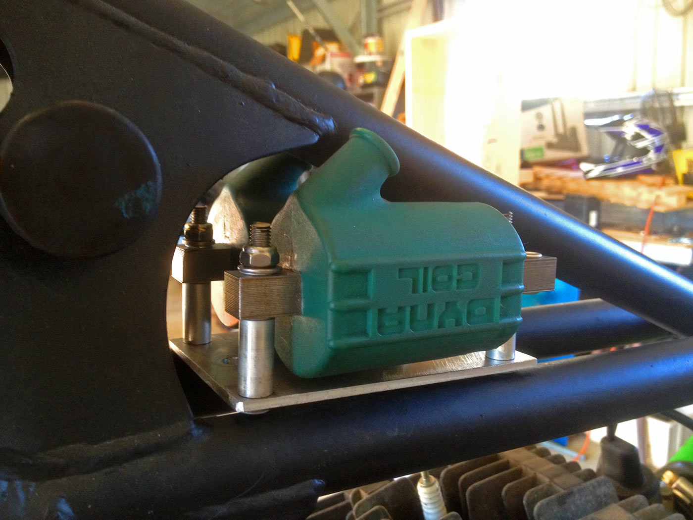
They really look nice and the green matches the Hawaiian green of the factory tank!
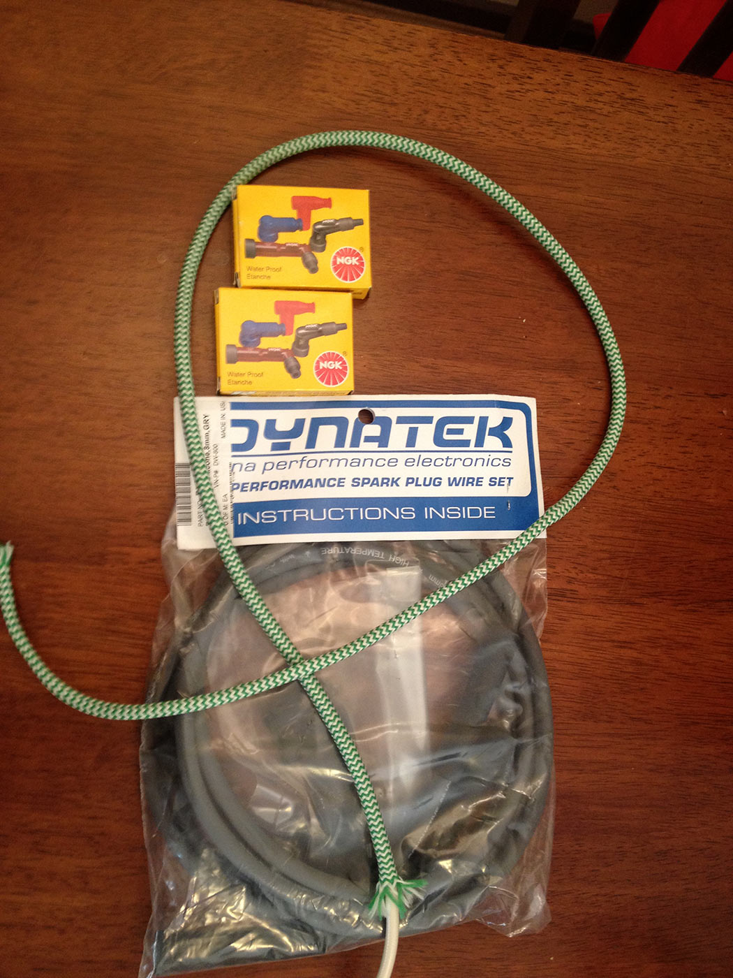
Ignition wires and spark plug caps! The fabric wiring was meant to be the sheathing for the spark plug leads but it just didn’t work. So, no sheathing.
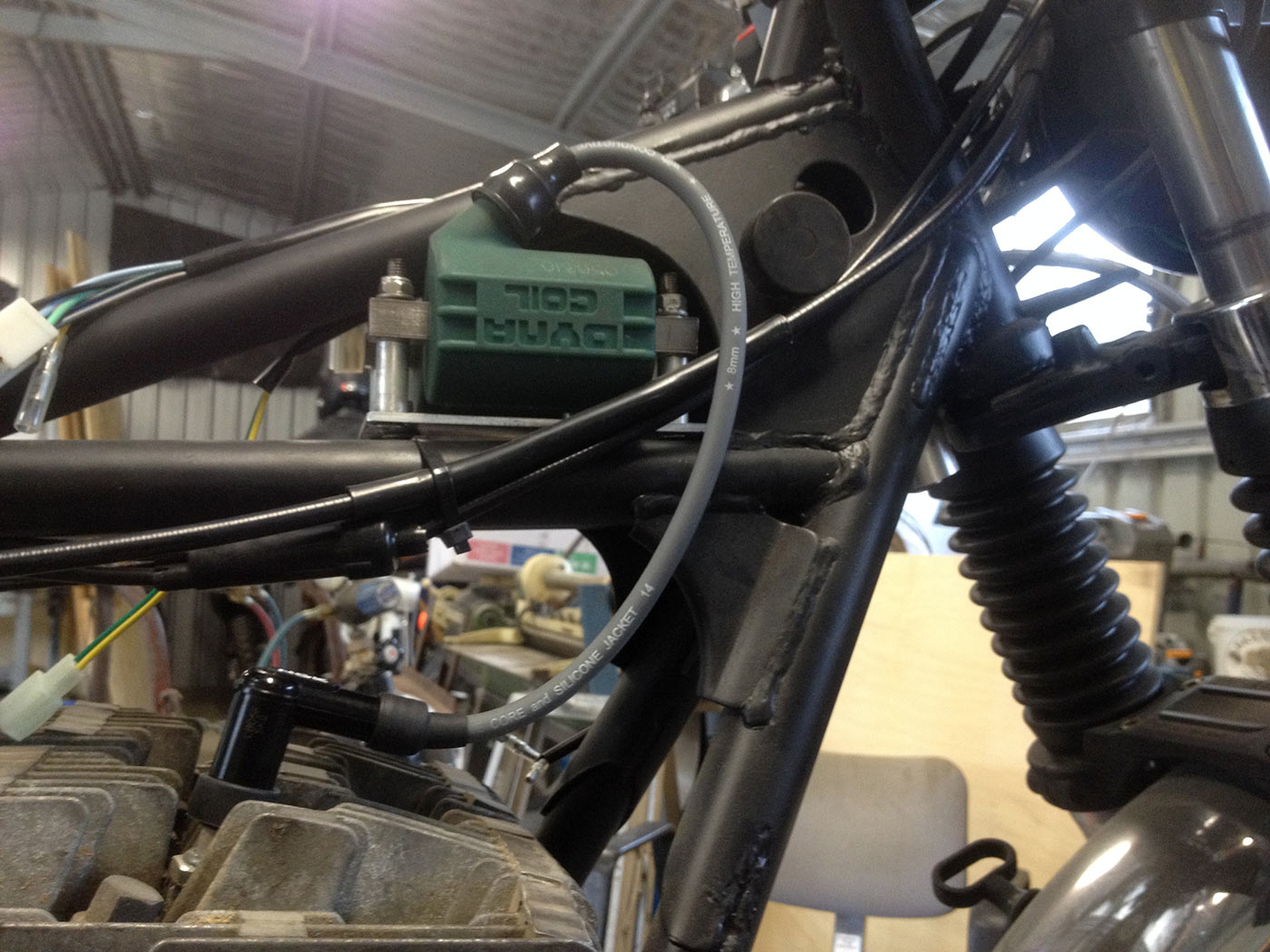
Wiring done to the spark plugs leads. Just looks awesome.
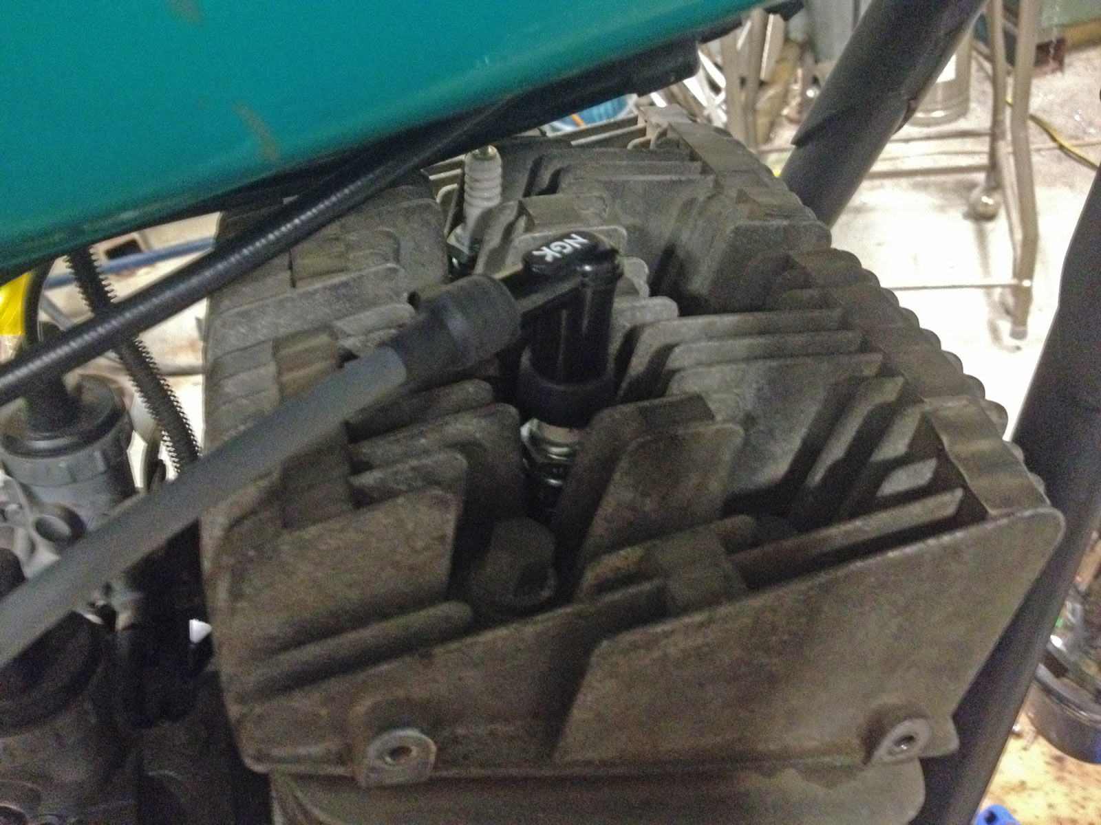
Dyna wires and new NGK right-angle plug caps make it look fairly factory, though admittedly with fatter shielded wires it should be better.
Ignition system
The points ignition system is a pain to keep happy – you’re forever adjusting points, burning out condensers and the like. Plus it can make the bike hard to start, especially in winter… so, with that in mind, I went with a replacement setup. The ideal replacement would be a higher output stator and electronic ignition in one, but at 500€ this was a bit rich. Instead, I went with the NewTronic optical pickup setup.
Installing this is not particularly tricky, you just have to do some fiddling underneath the left-hand side engine case.
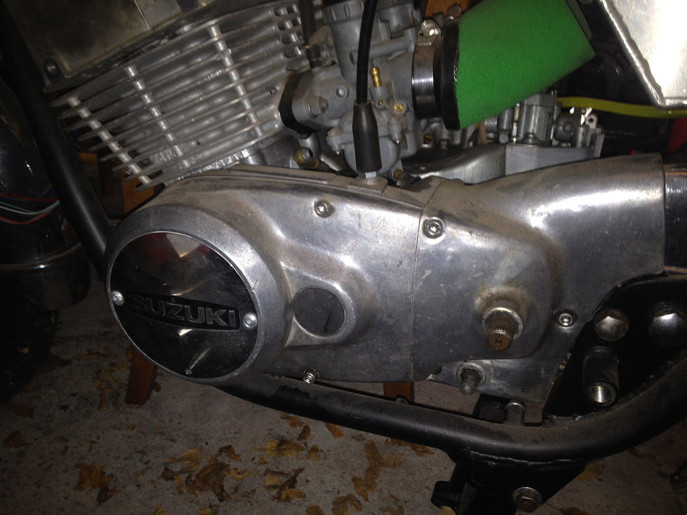
Underneath this cover, that is. It all has to come off.
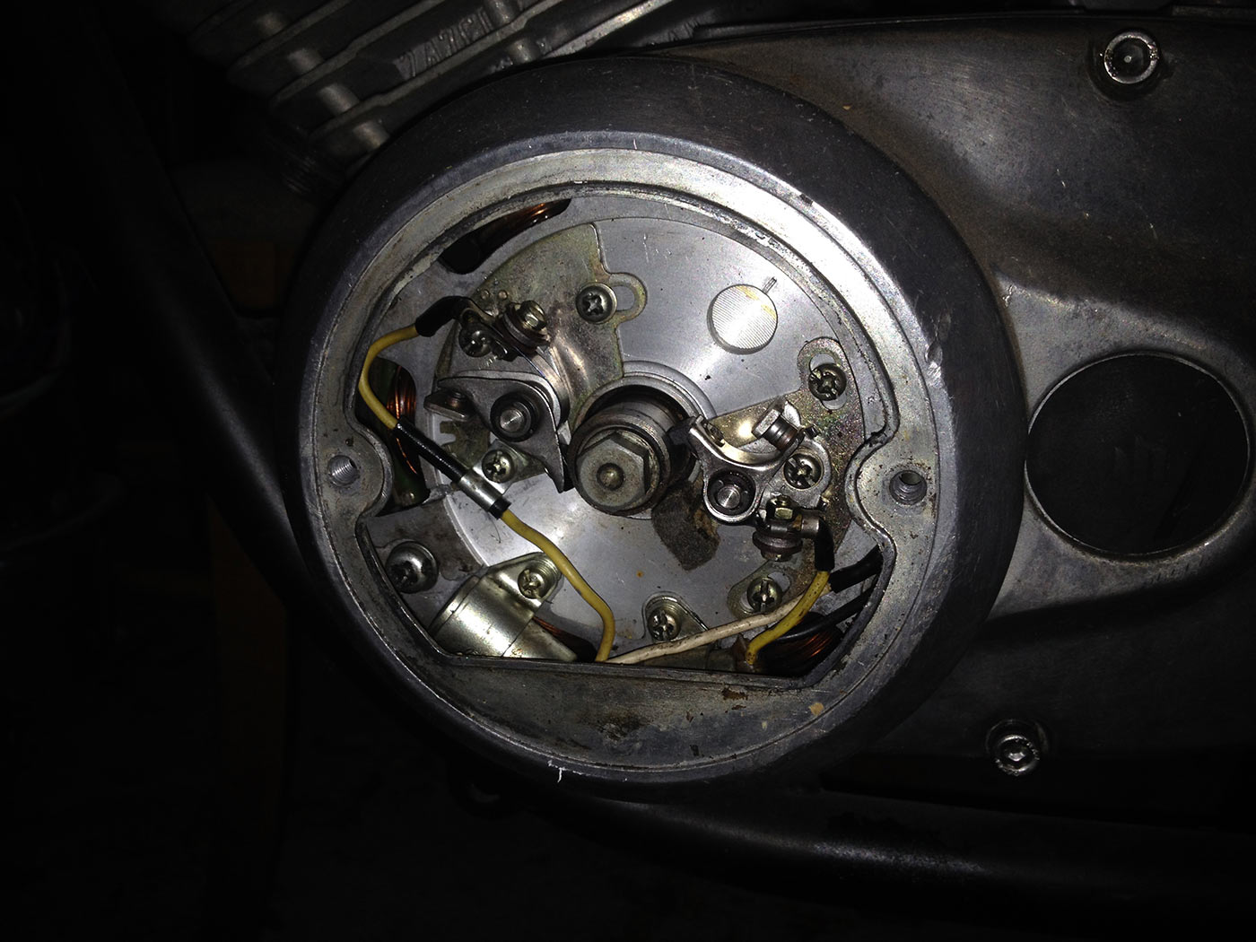
Ignition points cover removed. The Newtronics system replaces the points and the condensers.
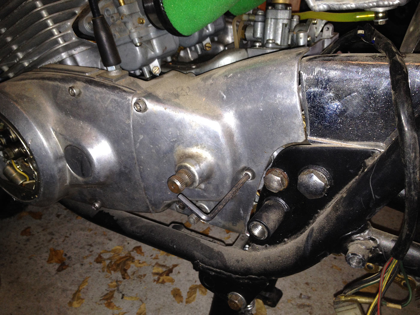
Whip off the front sprocket and generator cover with the allen keys.
(More later)
Charging system
At this stage, I’m not doing anything too fancy to upgrade it. I am, however, replacing the separate regulator and rectifier (which are fairly rubbish) with a modern solid-state single phase (but two wire) regulator-rectifier. The reg-rect I bought was just a cheap one off ebay, designed for 1960s-1970s Triumphs.
There are some great discussions about charging system options at these two forum posts: http://www.suzuki2strokes.com/forum/viewtopic.php?f=29&t=4824 and http://www.suzuki2strokes.com/forum/viewtopic.php?t=4858
You’ll see pics of how I mounted it in the section below.
Hiding away all of the electrical things
One of the mega headaches I had was where to hide all of the wiring stuff. I didn’t want to cut the frame which added some complications; it would have been easier if I’d just put a few holes in the frame to bolt stuff down. Adding in a modern regulator-rectifier (much larger than the stock setup) and electronic ignition control unit (which is designed to be hidden behind the battery compartment cover) just adds to it.
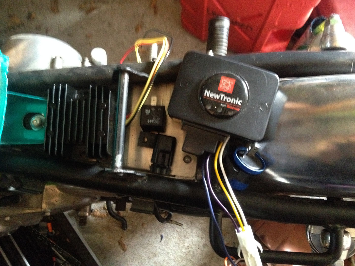
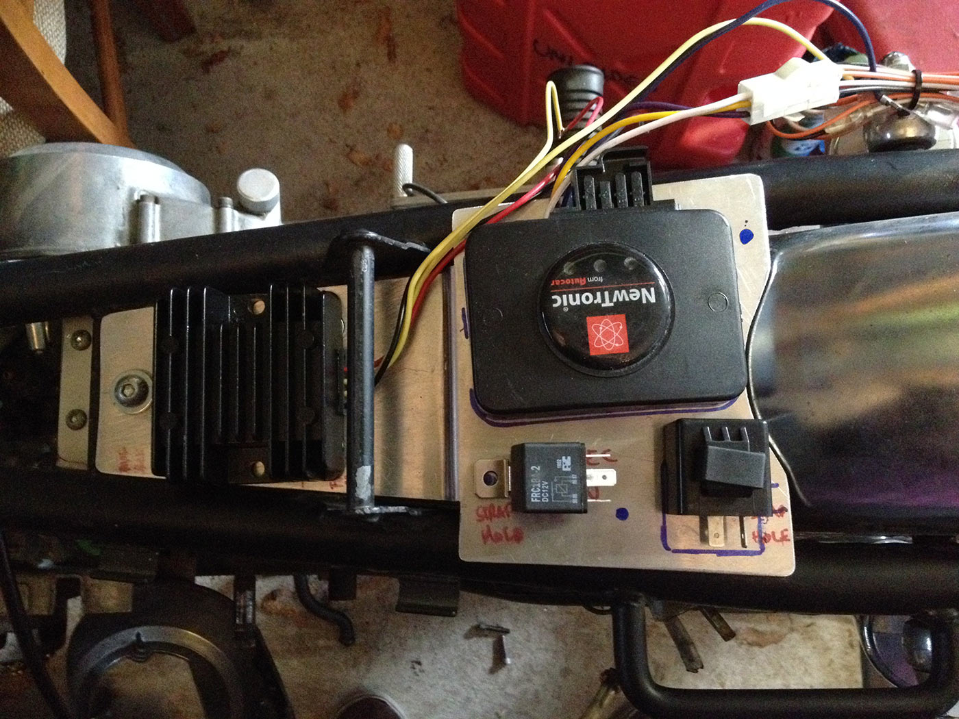
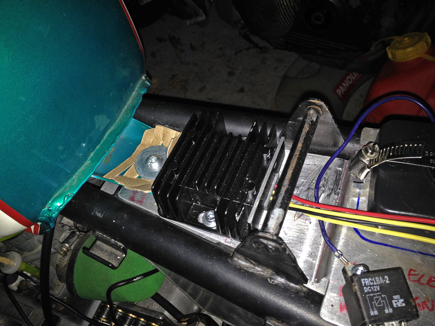
Everything I have to fit in. Regulator-rectifier, main relay, fuse holder, electronic ignition and electronic indicator flasher all needs to hide somewhere.
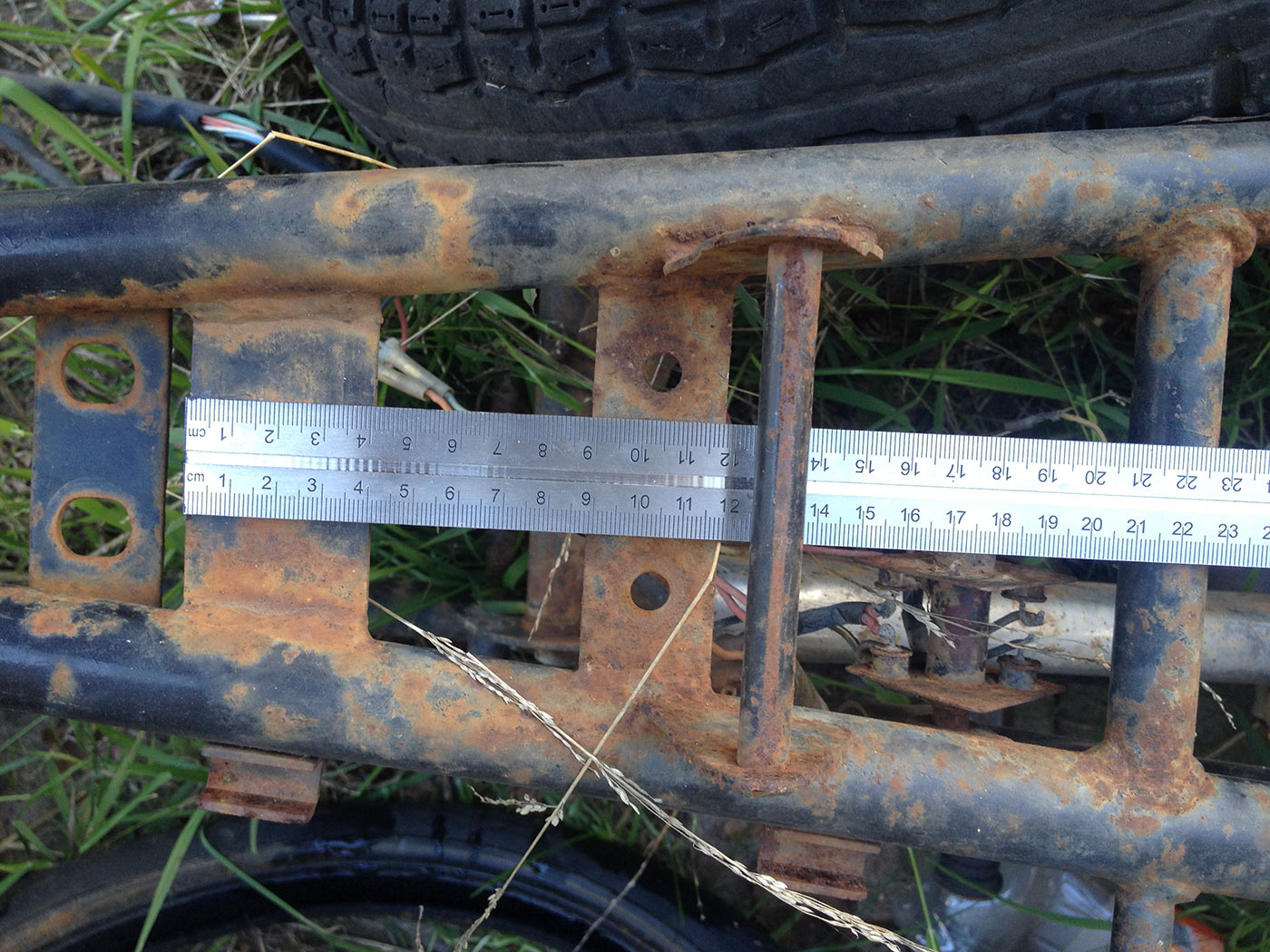
Having a spare frame makes measuring everything much easier.
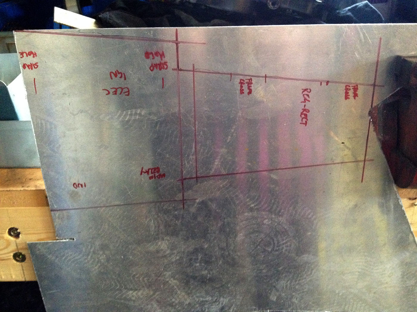
Cardboard template is made up, then translated to the 2 mm aluminium plate to then be cut out.
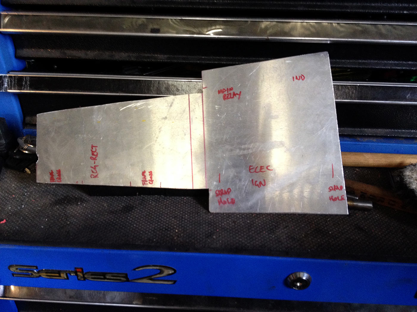
Roughed out and filed up. The bit between the left and the right-hand side needs to be bent. The lower part will hold the reg-rect and be low enough to clear the set, and the higher, wider part will hold the rest of the stuff. At this stage, I wasn’t sure where to fit everything.
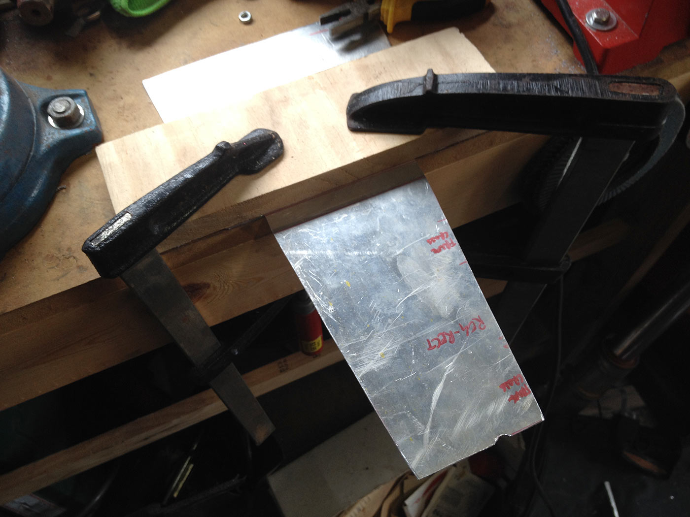
Bending the plate using the work bench and a bit of wood. Nothing complicated here.
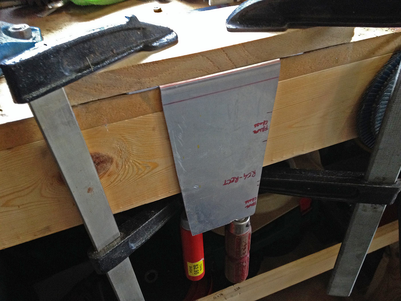
Bent! Now this tongue bit gets bent back to provide a nice offset.
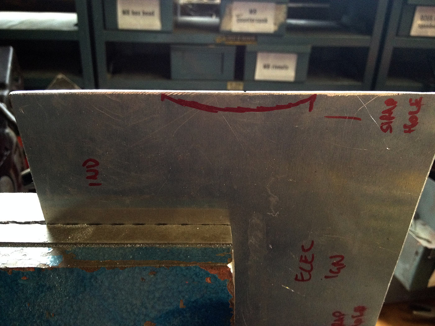
Small bit needs filing back to clear the mudguard.
Lots of test fitting to see where everything will fit.
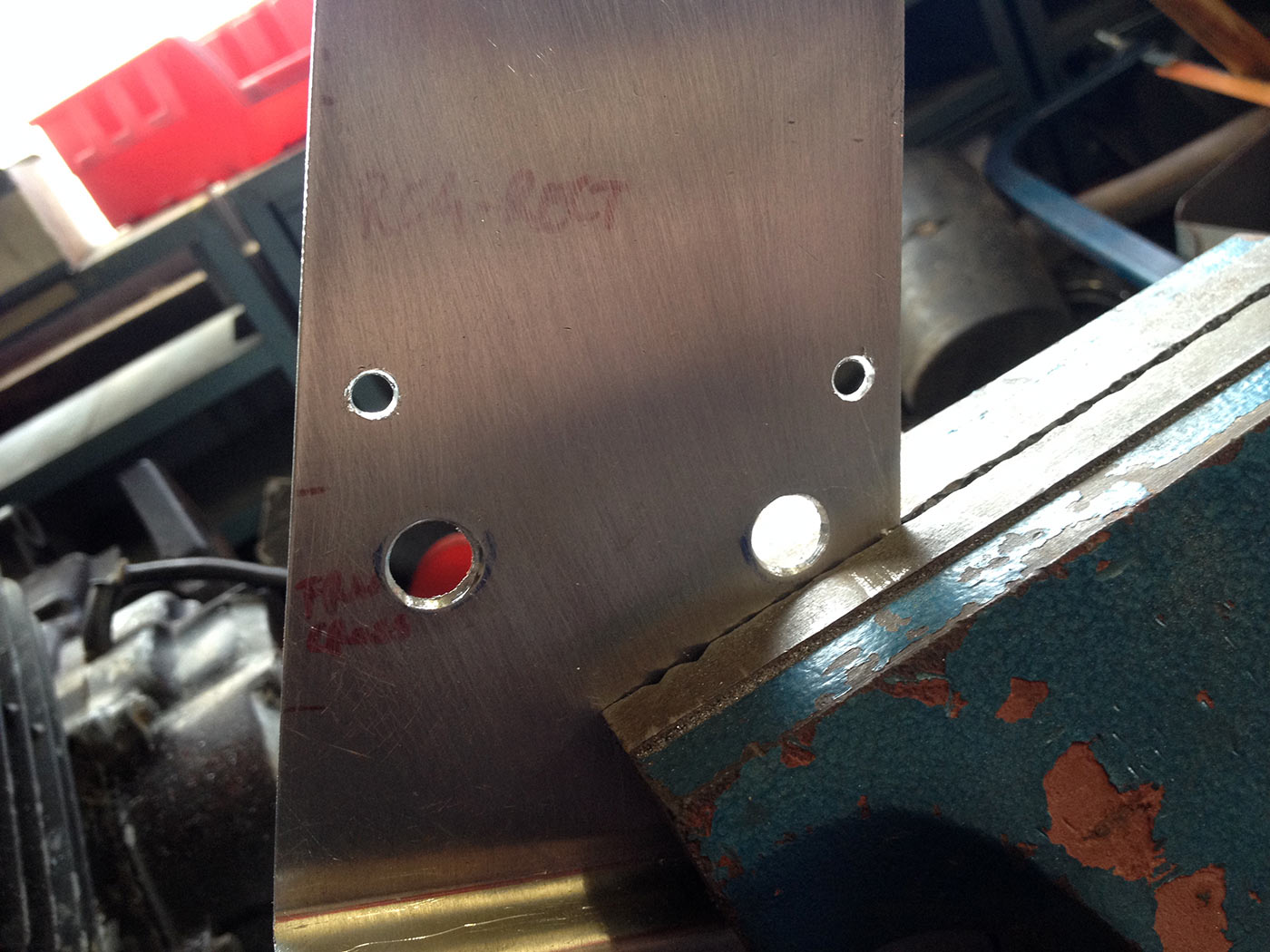
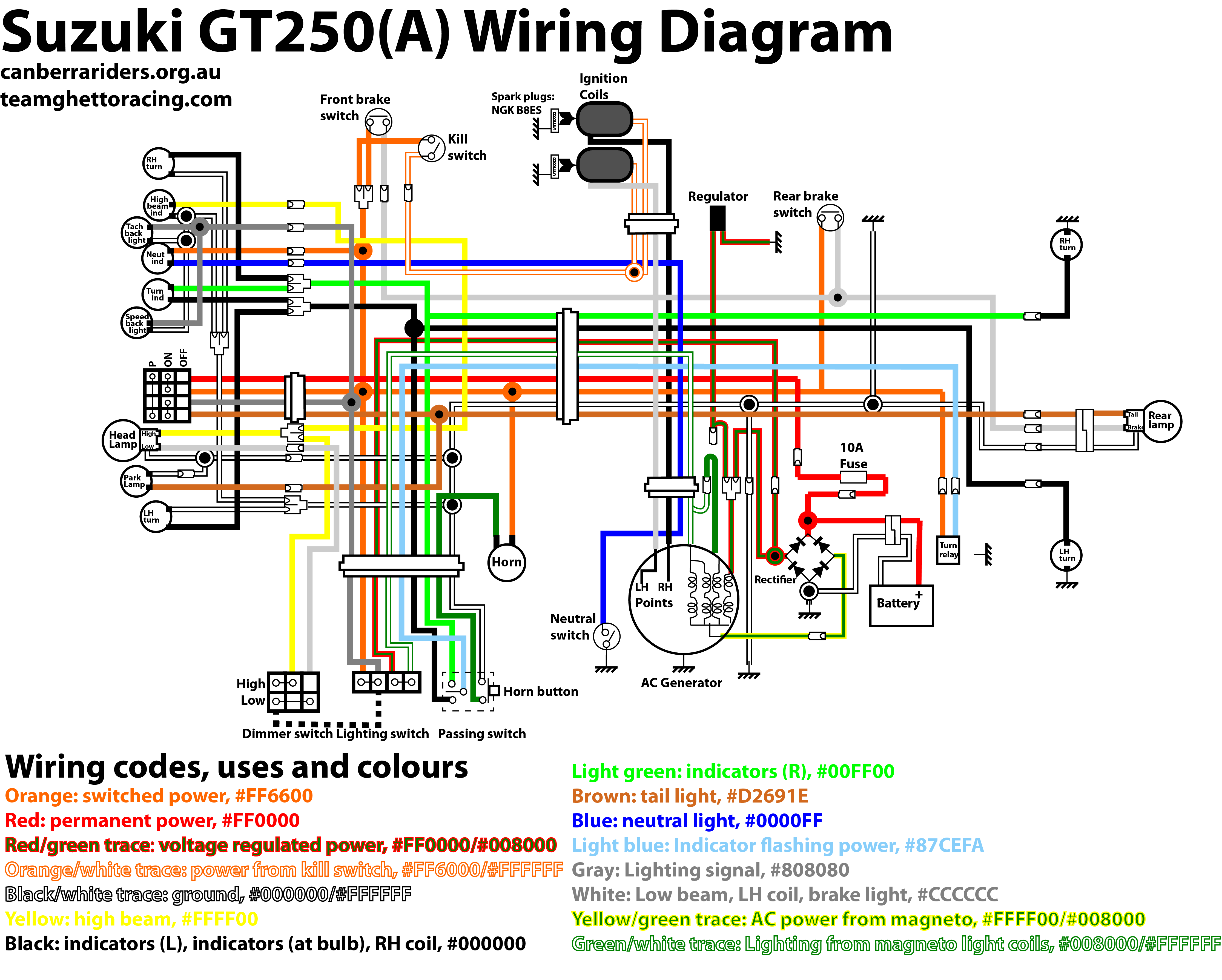
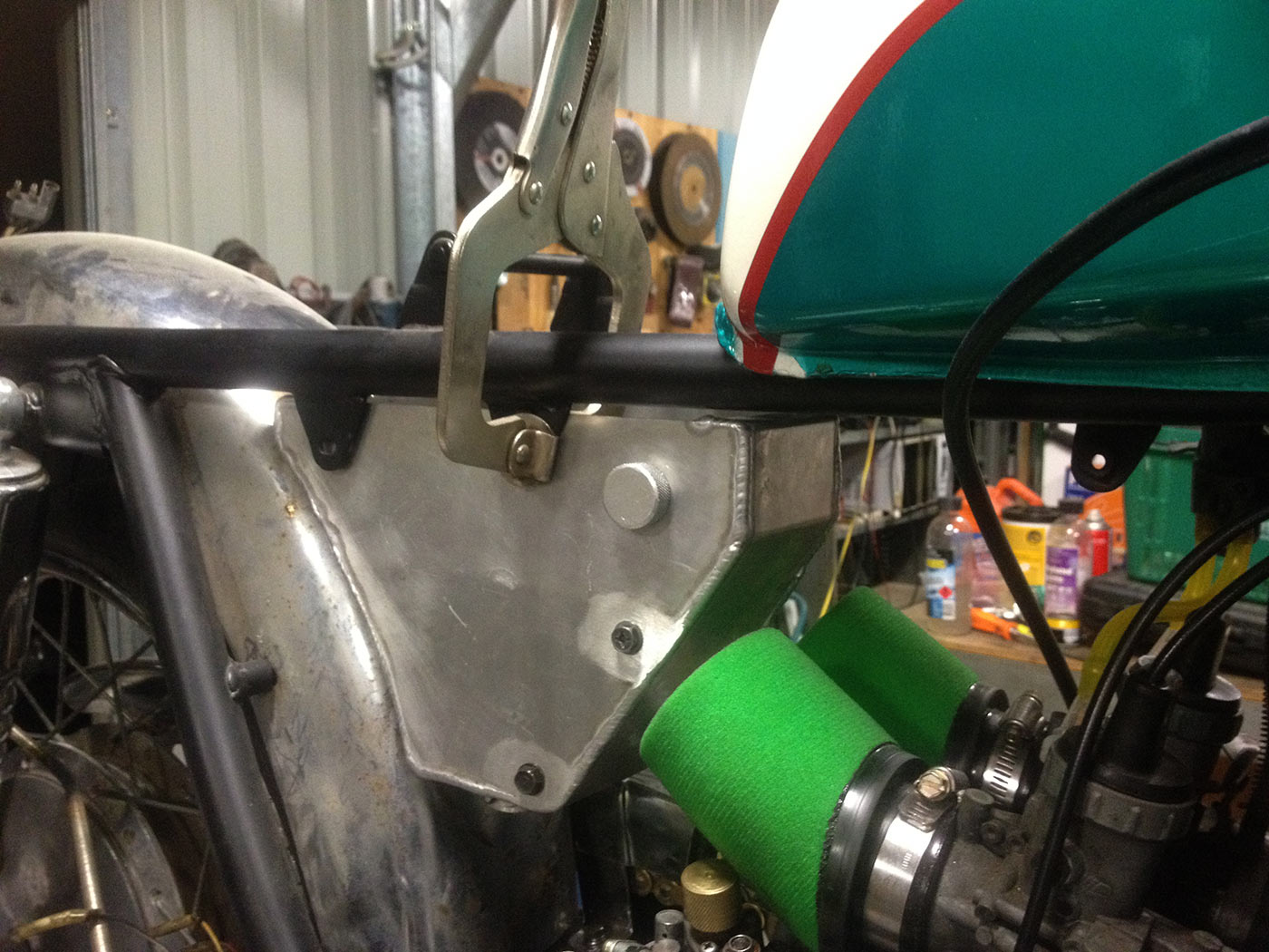
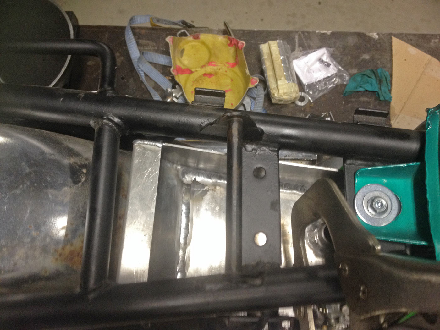
Mounting the reg-rect part: the two larger holes hold M6 countersunk bolts that fit into a frame member I put nutserts into the original holes (which were designed to hold the airbox). The smaller holes will hold M5 nutserts.
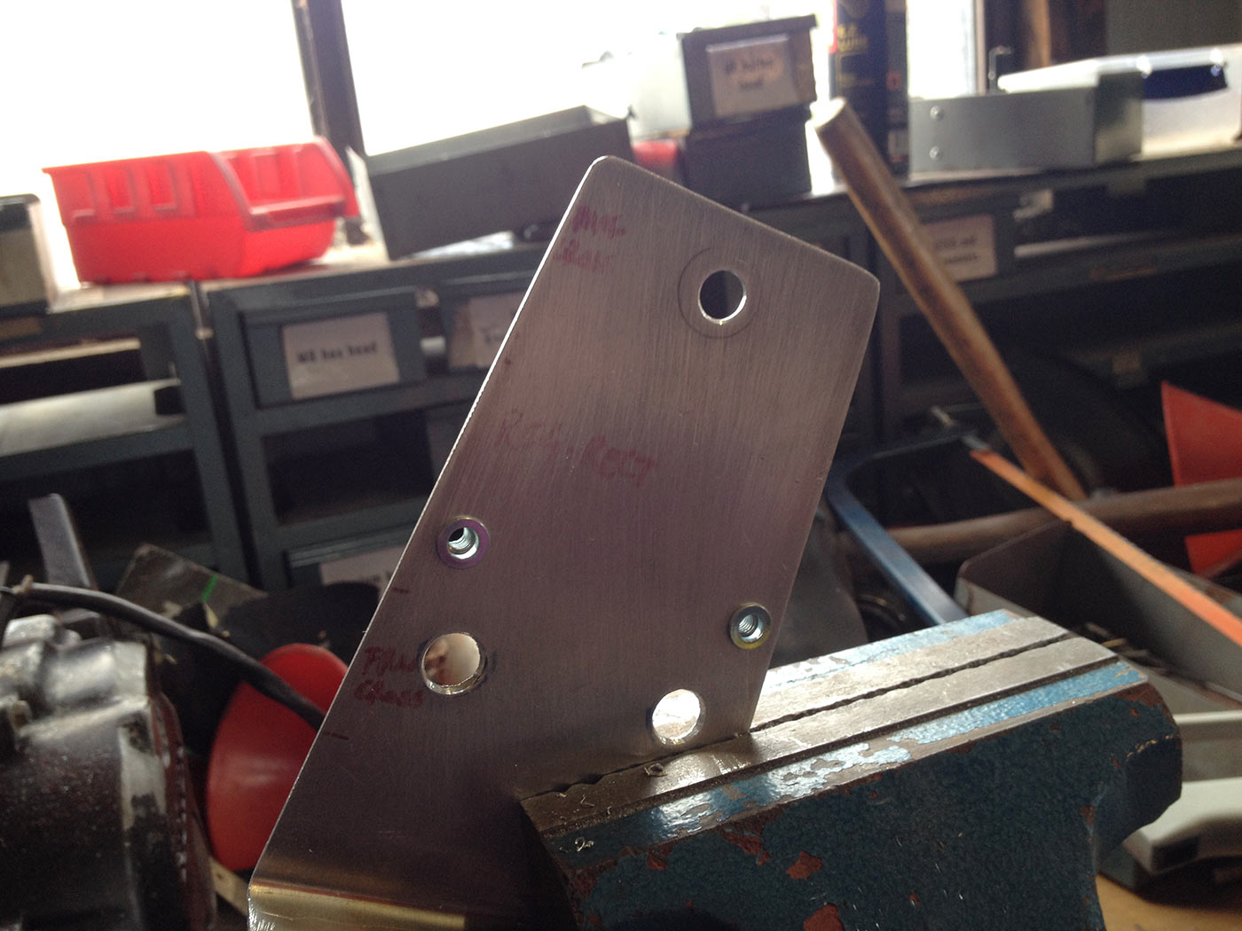
Nutserts installed for the reg-rect.
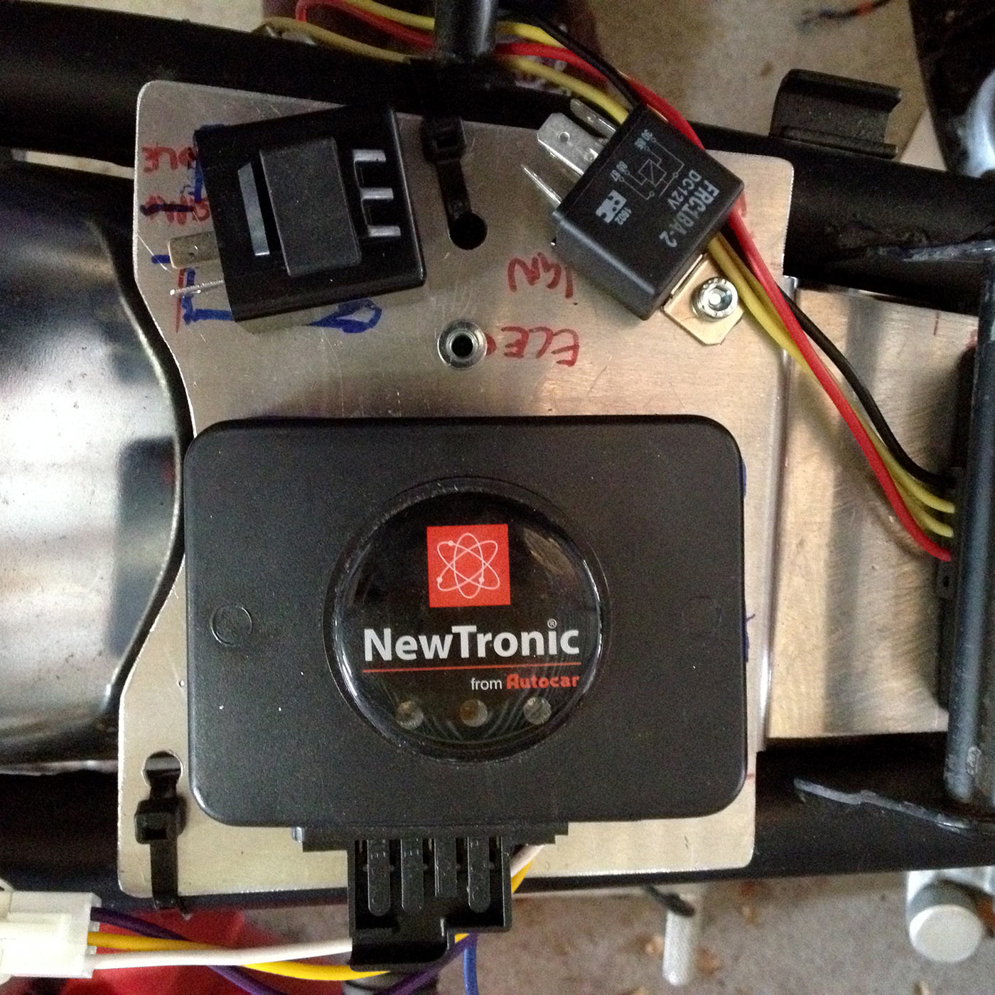
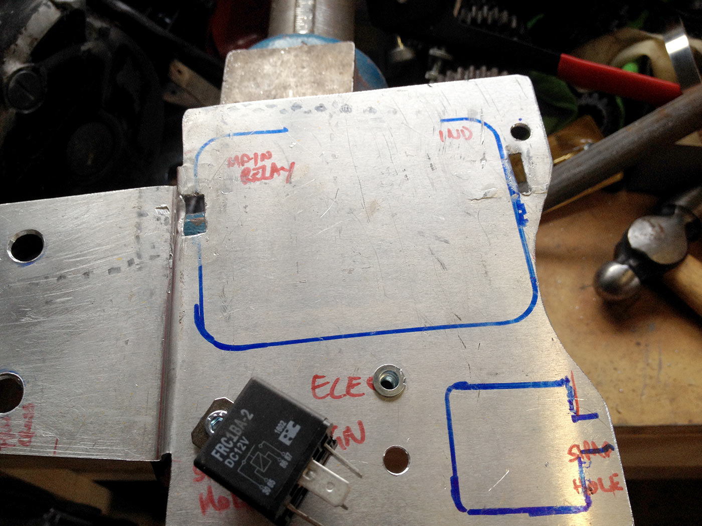
You were probably wondering how I would bolt down the ‘back’ part of the tray without modifying the frame… solution: cable ties. It works! Nutsert between indicator relay and main relay is for a wiring harness clamp.
Looking good. Need to mount the indicator relay and ignition module now though – and how to do that easily?
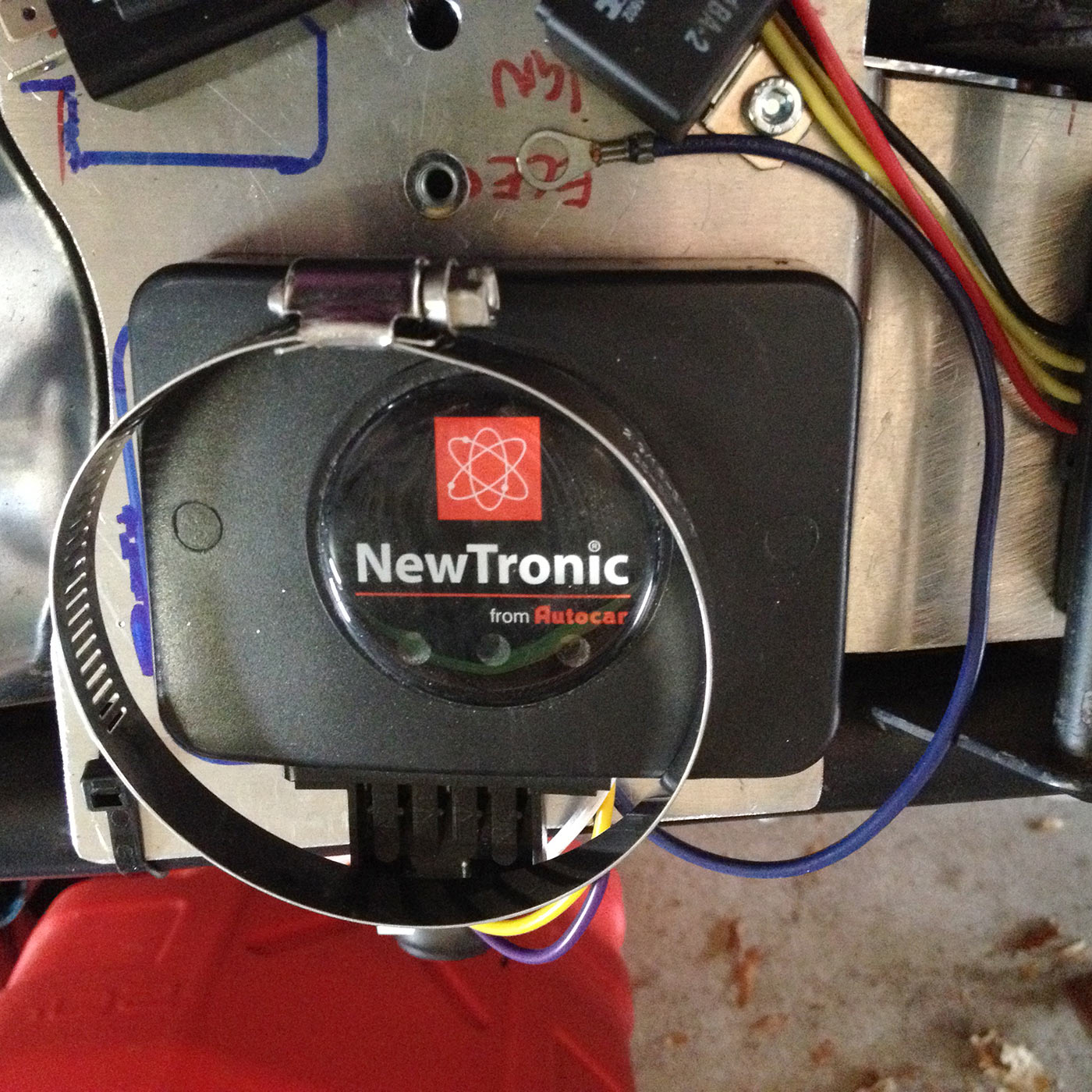
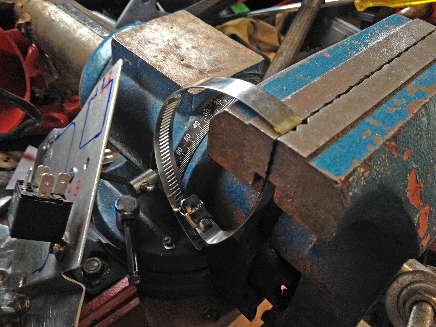
Solution? Big hose clamp! I bought two packs of 16 different sized stainless hose clamps at Bunnings for $1.50 each (clearance stock) and they came with this perfect large clamp for the ignition module.
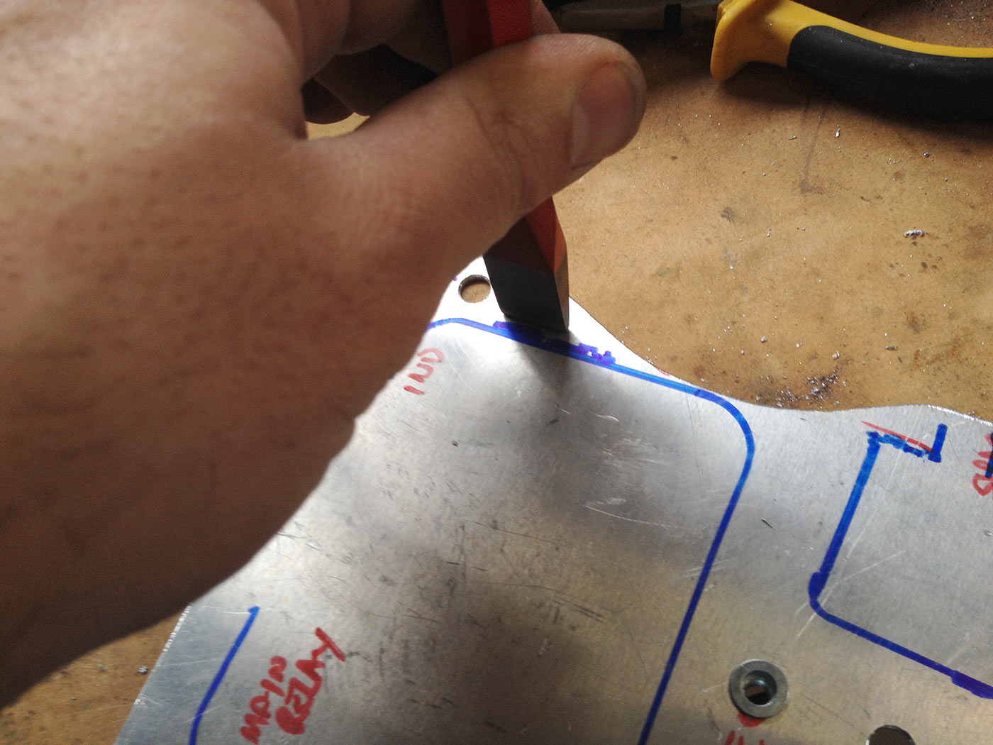
With no slot cutting die and press setup, I had to improvise. Cold chisel that is wider than the hose clamp is perfect for this.
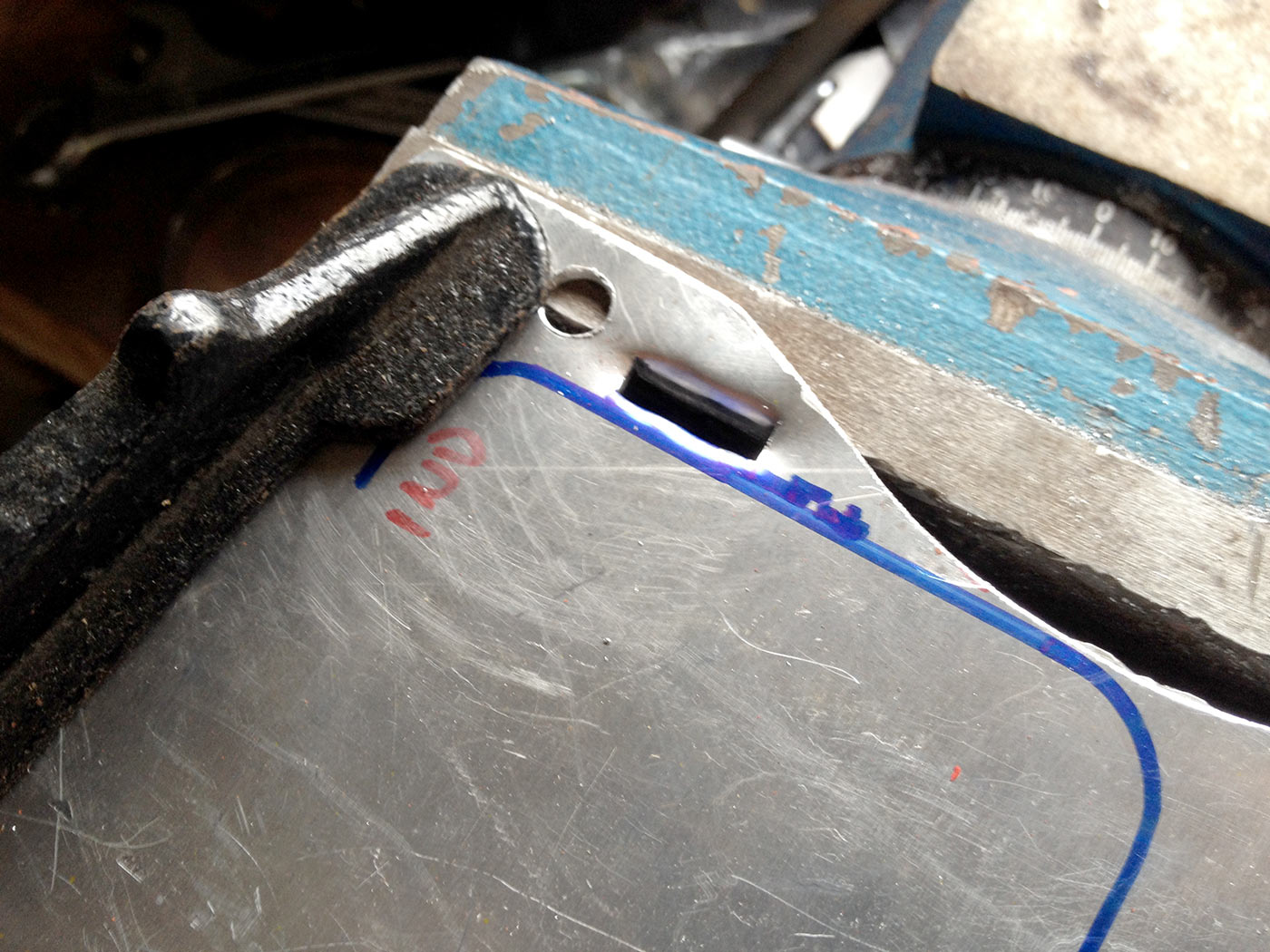
After starting, I used the vise to make the perfect aperture. Lots of cleaning up at the back side was needed, though.
Ugly slots at this stage but a bit more filing made them perfect.
You need to bend the hose clamp at 90 degrees and straighten up the various parts to make it work perfectly.
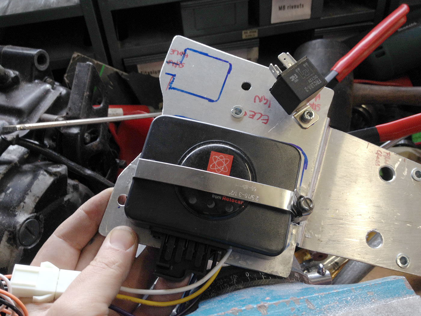
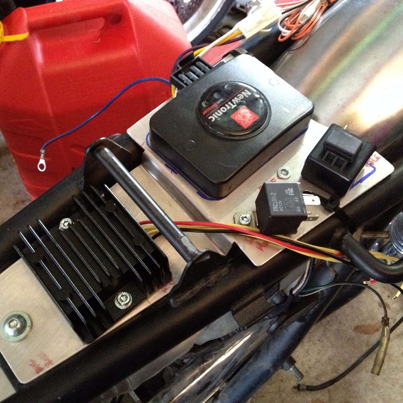
Perfect. I’ll put some foam underneath and on top of the ignition module to damp vibrations but right now this is perfect to get the wiring sorted.
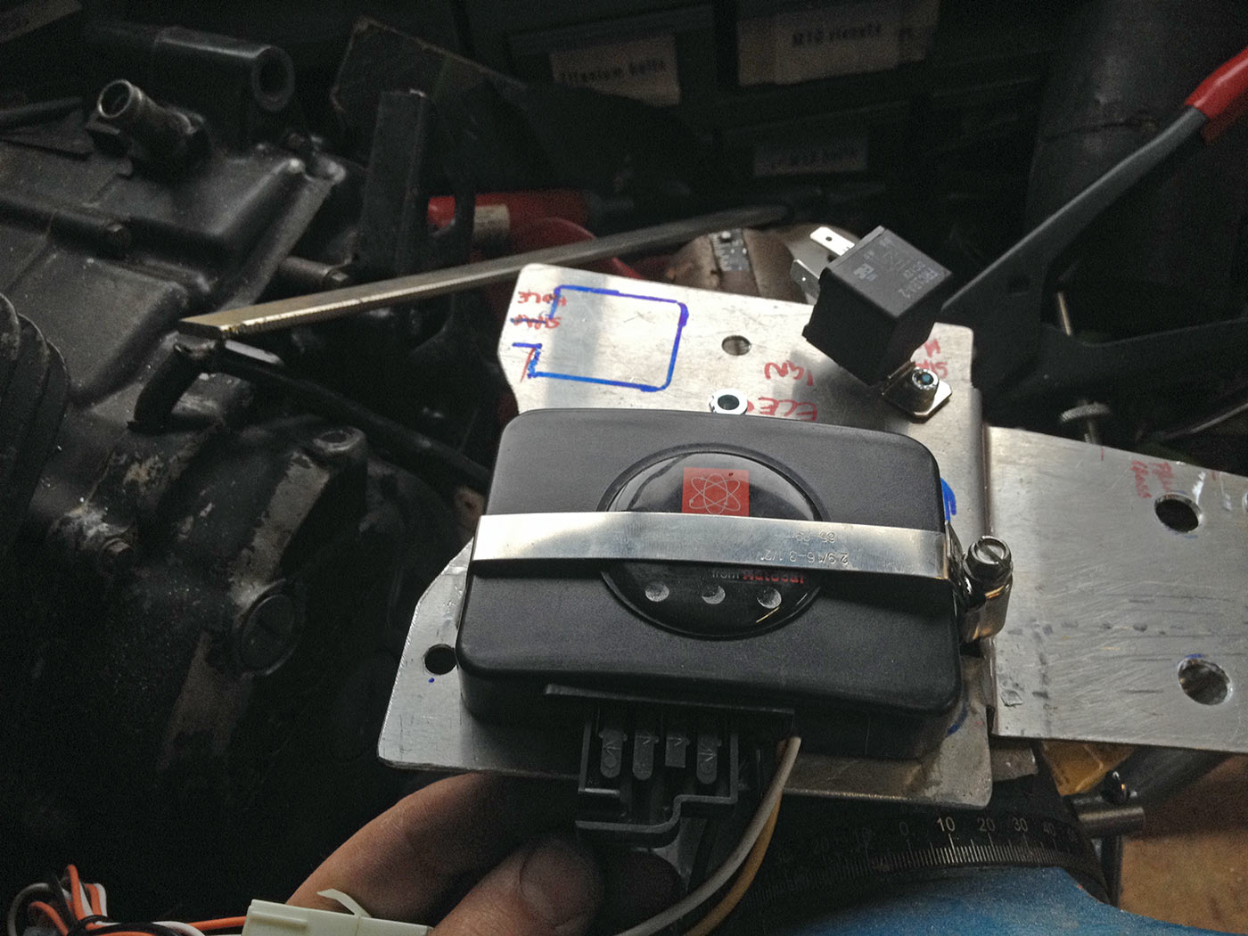
Works really, really well and fits absolutely brilliantly.
Same principle applied to the indicator relay.
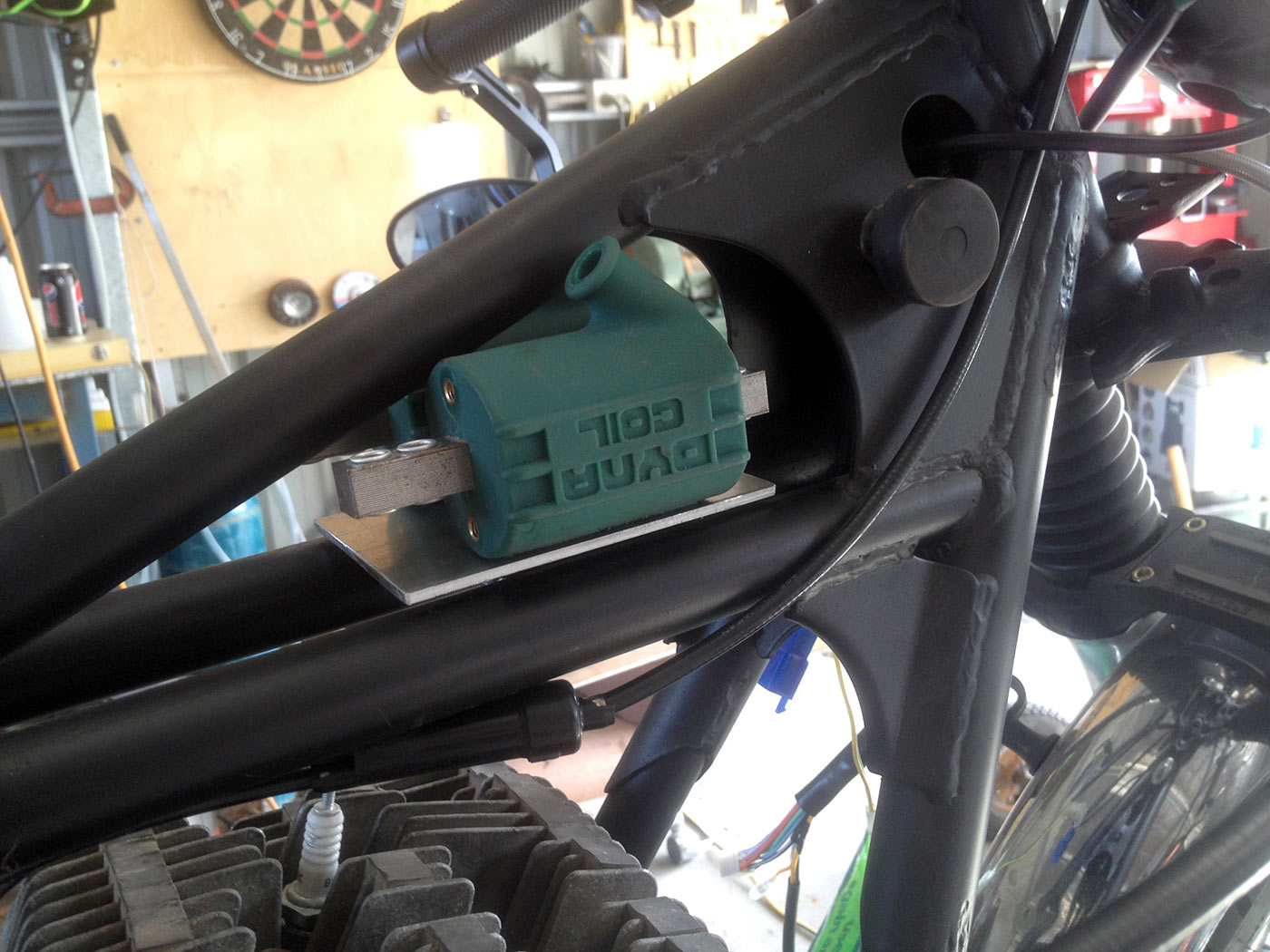
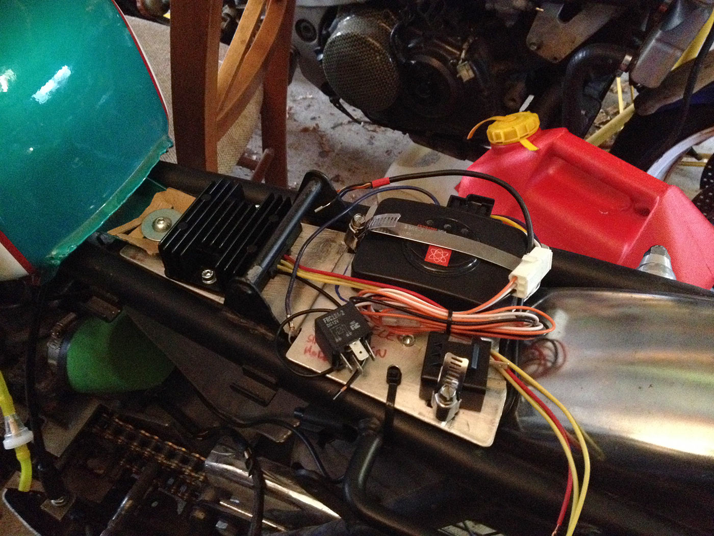
Small hiccup with the reg-rect. I was testing the fitment using the seat base that came with this frame, but the actual seat I’ll be using initially/for pillioning duties is a later model one (76 or 77 model, I think). The bit at the front is slightly different and it was fouling on the reg-rect fins. I trimmed the fins but I also had to slot the mounting holes to move it slightly forwards. Just clears the fuel tank though. Cardboard is because I don’t have the tank mounting rubber for the back mount yet.
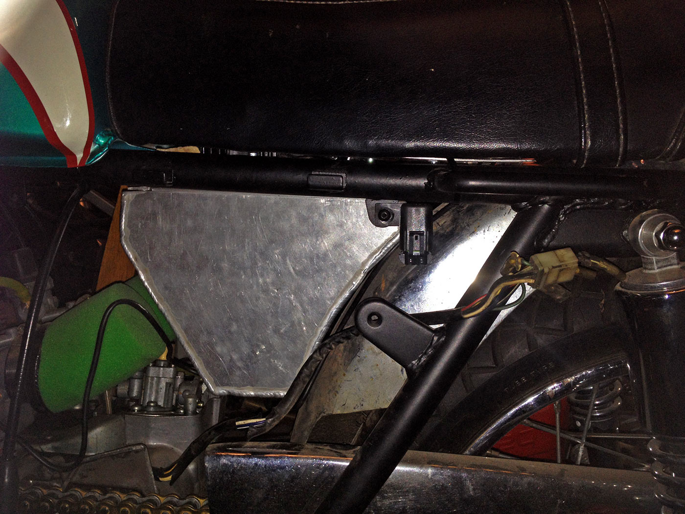
Had to find somewhere to fit the main fuse holder. I wanted to hide it under the seat but, to be honest, it’s nicer having it available without having to dismantle the entire bike. Hanging off here it is not obvious. It will also nicely fit in with the planned main battery connection which will also be on this side of the bike.
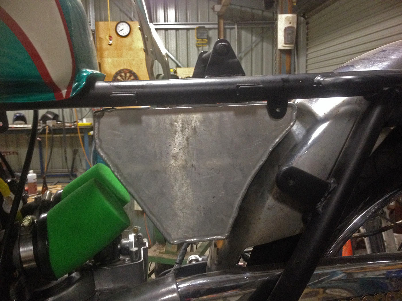
Nice to have everything hidden without having the standard side covers or anything in there.
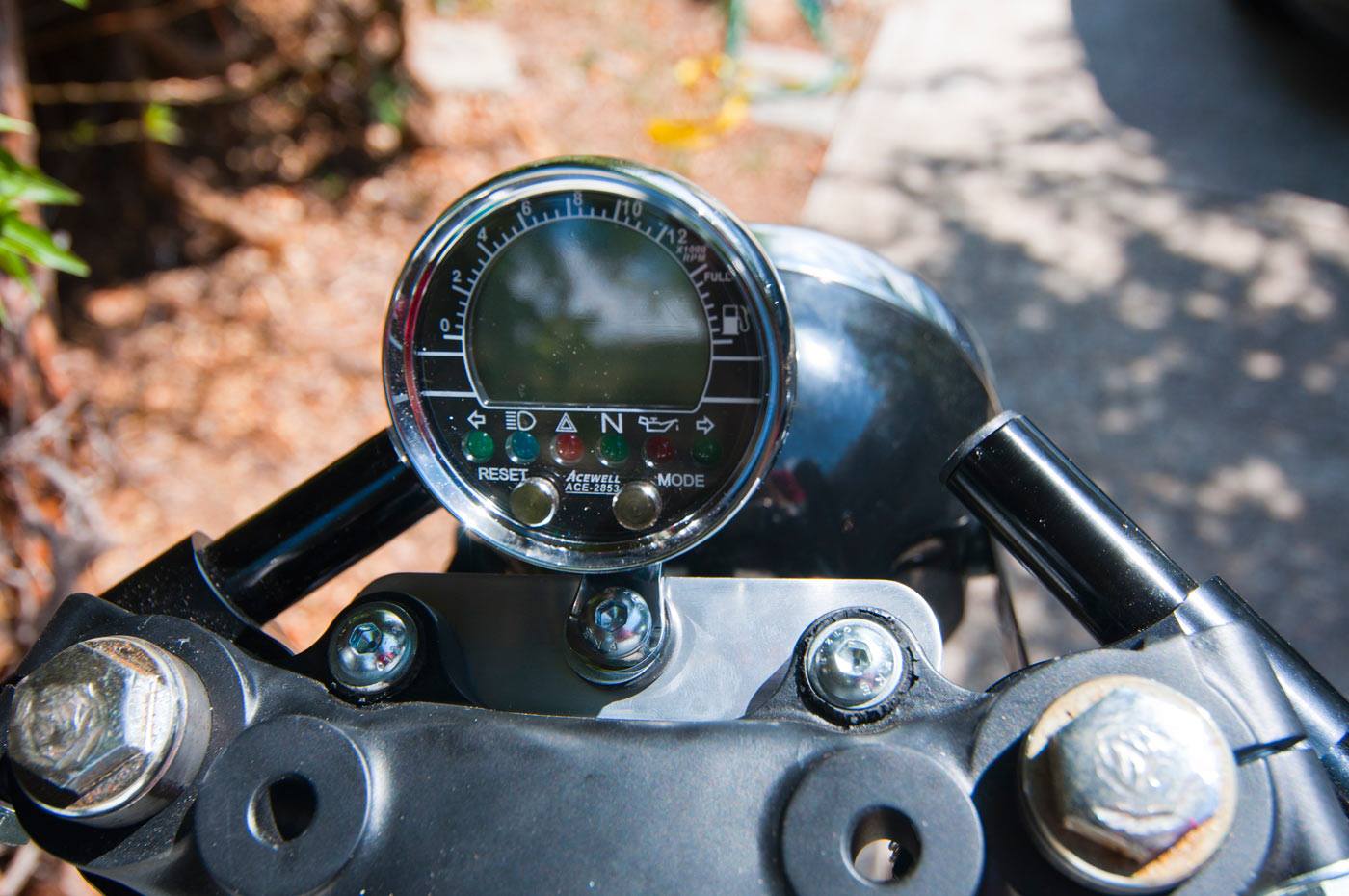
Speedo/tacho
I decided to replace the speedo/tacho with a nice Acewell unit. I mounted it up on a little bar on the triple clamp and all is good.
Brake light switches
Ah, now here’s a dilemma. Way back in the day, my first ever GT250 didn’t seem to have a front brake light switch – and I got by with just using the rear brake as well as I slowed up to activate the brake light. On this one, I’m using a hydraulic front brake light switch off the front master cylinder, and a Ducati rear brake light switch off a Monster for the rear brake. More pics of the rear brake setup on the page for making up the rear sets.
Battery and battery compartment
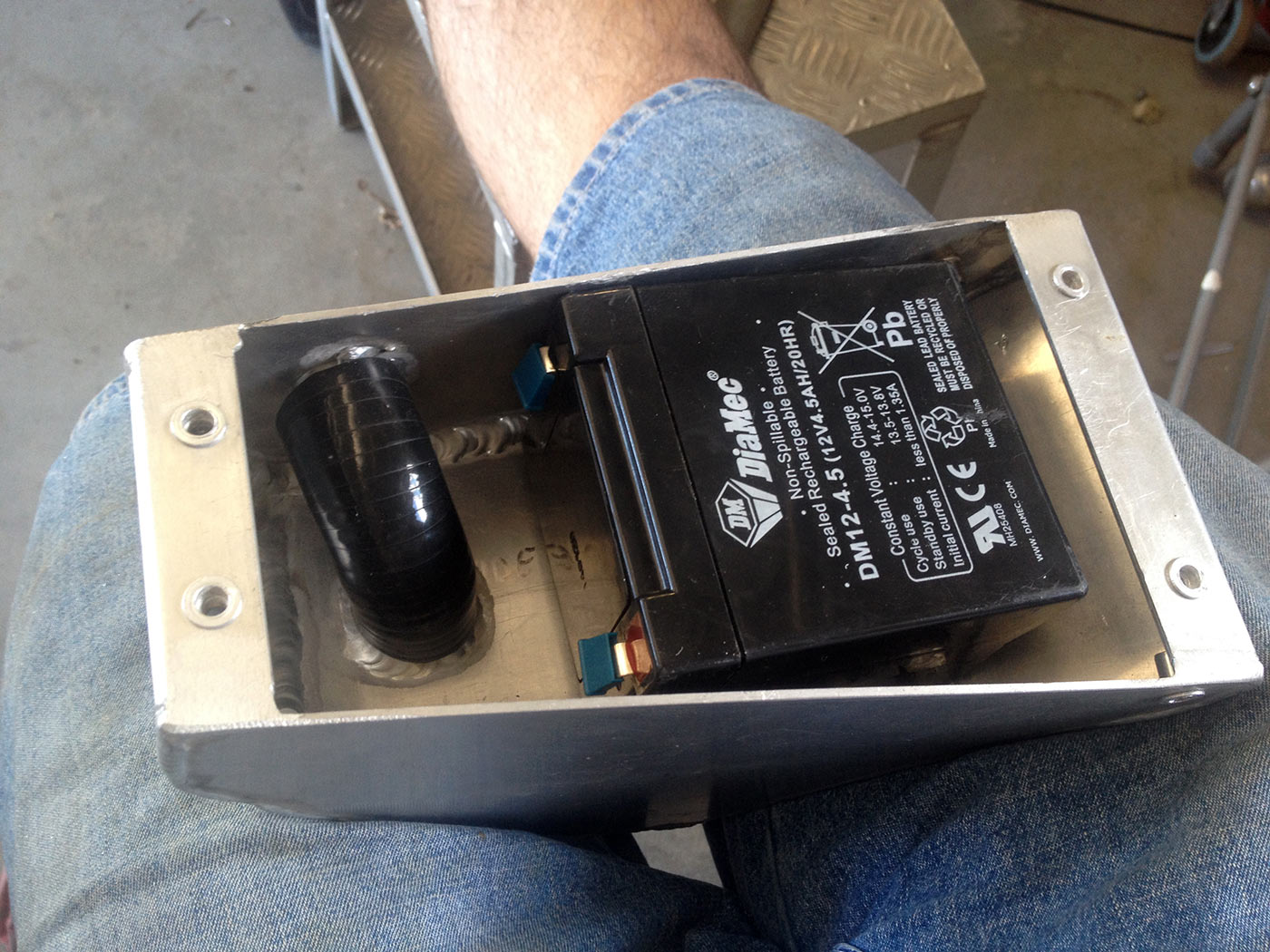
Upgrading the charging system to use a modern reg-rect should help with capacity, so I didn’t worry about absolute capacity (5 Ah is the stock battery). What I did want to do is integrate the battery into the oil compartment, so that meant I needed a dry battery I could hold at any angle.
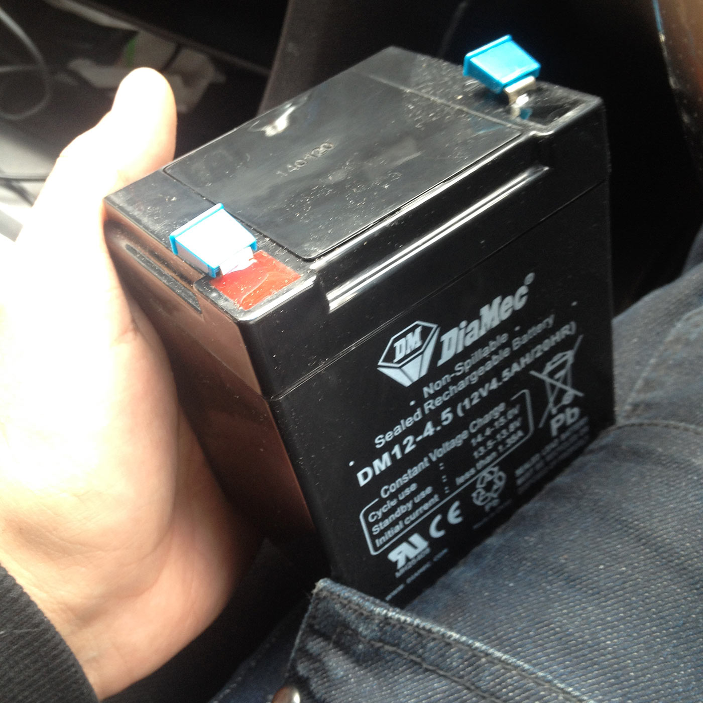
Perfect! Pretty cheap from Jaycar, these are from small UPSes. Almost the same capacity as a stock one, but much smaller.
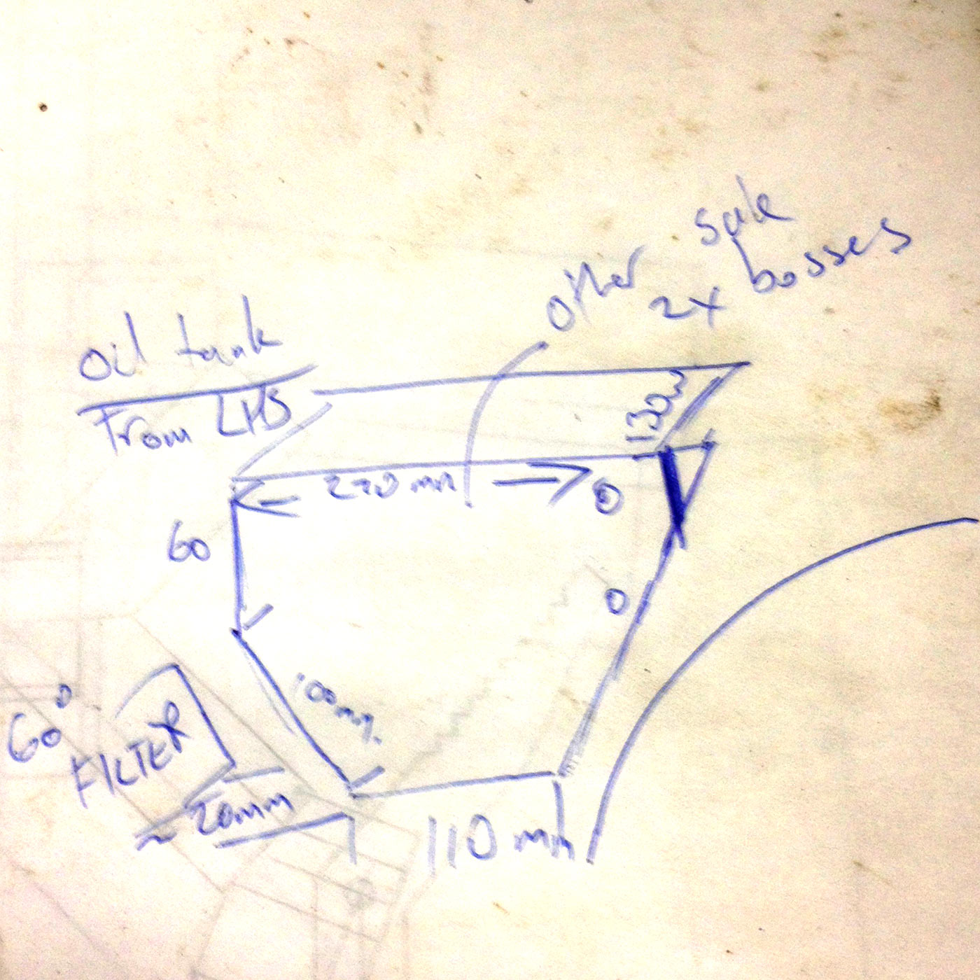
Horrid drawing but this was the basic setup for making the oil compartment.
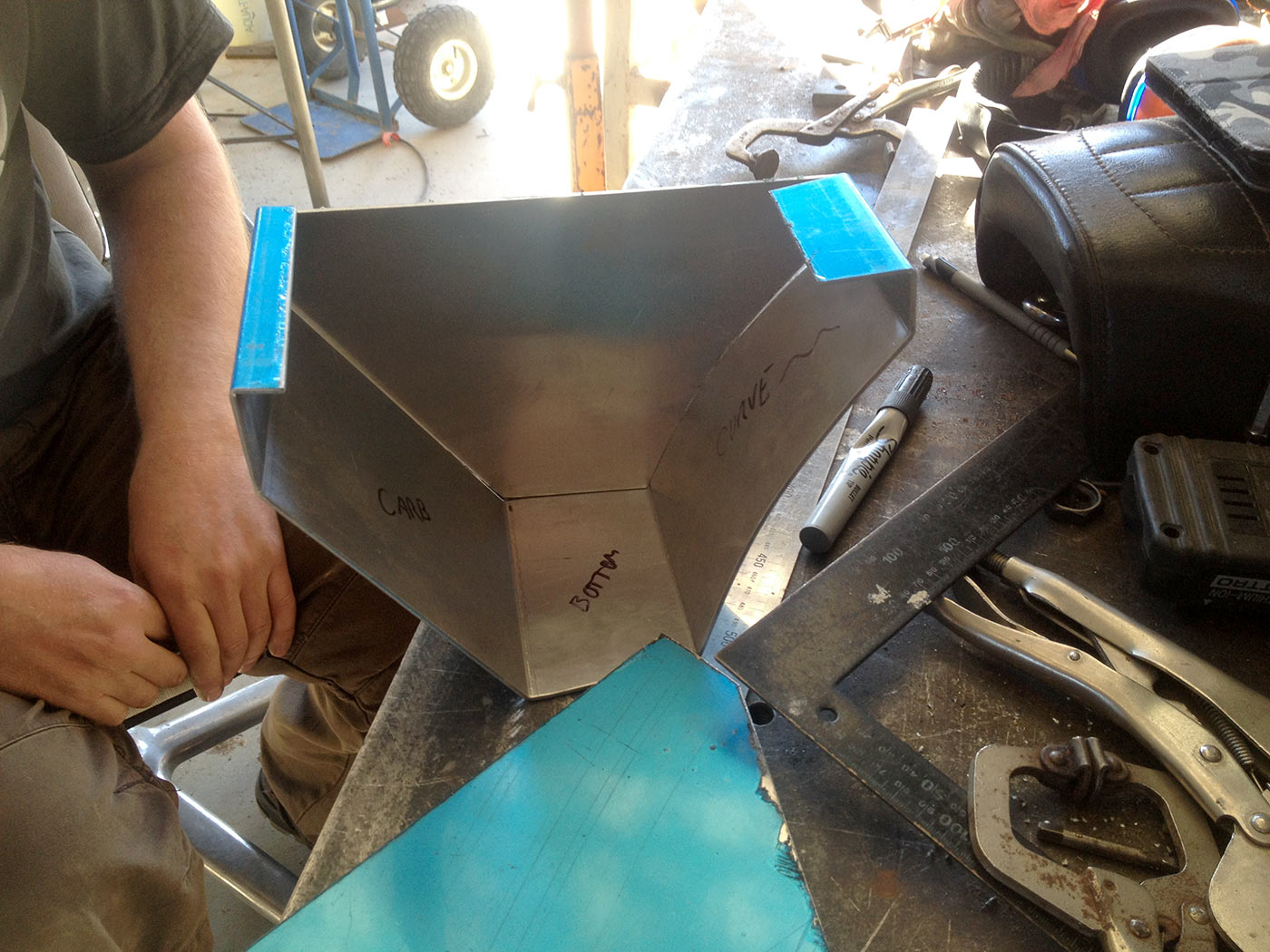
Cutting out and bending the aluminium for the battery/oil compartment.
Idea is to weld all but one side and the top in. Then the battery tray can be put in, the final side can be welded in, and then the top bolts on and off.
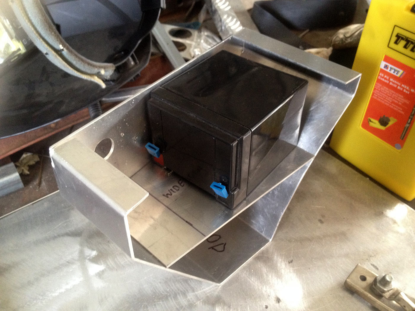
Battery sitting on its tray. Perfect height just to sit in the right spot.
Checking fitment of the oil compartment/battery holder.
Looking down into the compartment. You can see the holes in the frame member that I put nutserts in to hold the electronics tray.
View from the left-hand side. Eventually this will have a multi-pin connector for the battery connection to the rest of the bike. This will make things much easier to disconnect if needed. I’ll also make it so I can disconnect it from the bike and connect the battery directly to a battery charger.
Battery sitting in its spot with the oil fill pipe installed. Just need to make the electrical connection to the outside world and job done.