
Electrical 201: switches, relays and diodes
This isn’t exactly Jimny specific but I am going to draw semi laid out wiring diagrams, and try to work through some of the things you might want to know including why you’d select a relay and the like.
Sections
- Before we begin
- Worked example 1: rear camp light
- Worked example 2: switchable high current auxiliary power connection to rear
- Worked example 3: Independent power sources depending on car state
Before we begin…
I am going to illustrate the current flow in these diagrams but I want to make a note for the pedants. I’m illustrating current flow how people think of it: out of the positive terminal of the battery, along the wires, into the device and then back into the battery at the negative terminal using the earth pathway along the chassis. Strictly speaking electrons flow out from the battery at the negative terminal and into the battery at the positive terminal having followed the earth path to the device, then the positive wiring back to the battery. I’m aware of that (electrons being negatively charged, after all) but I’ve drawn the current pathways how most people think of them.
For everyone else: follow the arrows in the diagrams to understand how electricity is flowing to make it back to the battery to ‘complete the circuit’. A device will only power on if there’s a complete circuit through it from the battery and back to the battery. A lot of the time you ignore the ‘earth’, ‘ground’, or negative side of things as the entire car body/chassis is connected to the negative terminal of the battery (“negative earth”), though. This is why most wiring diagrams only illustrate the positive wires, but the circuit is completed assuming the device you are connecting is connected to a solid ground connection.
I will use sort of standard wiring diagrams and symbols for this drawing so you might get familiar with them. Doing so should help if you look at other more traditional wiring diagrams. Where a wire makes a bit of a loop over the top of another wire then that is to illustrate that it isn’t connected there. Where it joins straight on then that shows that it is connected there and branching off.
Wiring diagram symbols
Fuses

Squiggly line between two points; thinner than the wiring to emphasise that it should melt before the wiring does.
Push switches
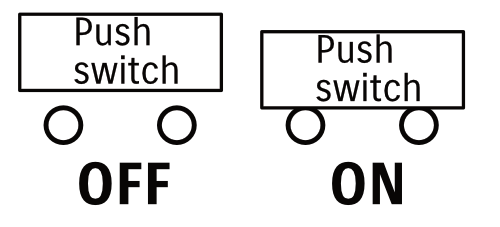
Couple of connectors with a plate that either separates them (switch is off) or touches them (switch is on).
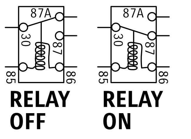
Relays
A lot of relays for automotive use are noted with a set of standard terminal numbers. I use these standard numbers in my diagrams for simplicity and so you can compare to many relays you will buy:
- Pin 30 is the high power/switched common terminal
- Pin 87 is a ‘normally open’ terminal for the high power/switched side;
- Pin 87a is a ‘normally closed’ terminal for the high power/switched side;
- Pin 85 (by convention) is the ground for the relay low power/switching side; and
- Pin 86 (by convention) is the low power/switching side positive input.
Note that pins 85 and 86 can be swapped in terms of which is +ve and which is ground/-ve and usually won’t cause an issue. You can also use these for ‘positive’ or negative switching:
- Positively switched relays will always have a pin (usually 85) connected to ground and the other switching pin (pin 86) will be connected to a lead which variably gets power when it is to be switched on/off
- Negatively switched relays will always be connected to power on a pin (usually pin 86), and then the switched side happens to connect ground to pin 85 when the switch is activated.
Also note that not all relays will have 5 pins, some will only have 4 pins.
A 5 pin relay is sometimes called a ‘switchover’ relay and might be what you use for activating high or low beam headlights, but also can be useful in other ways such as providing power to a device from two different sources (we’ll explore that later). In this initial example of a relay, a 4 pin relay would work as we only want to have the relay switching on or off power to a device based on the power of an input wire. I will draw it using a 5 pin arrangement, however, just as it shows how the switching part of a relay actually works.
With that out of the way, here’s a relay symbol, which hopefully shows how it is uses a small current (and hence small switch) to switch a much larger current. The current flowing through the coil of wire between pins 85 and 86 pulls down on a rod that switches the high power side of the relay over.
The exact current a relay can switch depends on the relay type: many will be limited to 30 or 40A, though you can buy ones with larger terminals good for 70A. Much larger relays often get called solenoids, or sometimes a ‘starter relay’ although they sort of aren’t a solenoid and they’re called starter relays as a common use is the switching of high current into a starter motor. I use a 500A relay to act as an isolator for my winch power cable.
Diodes
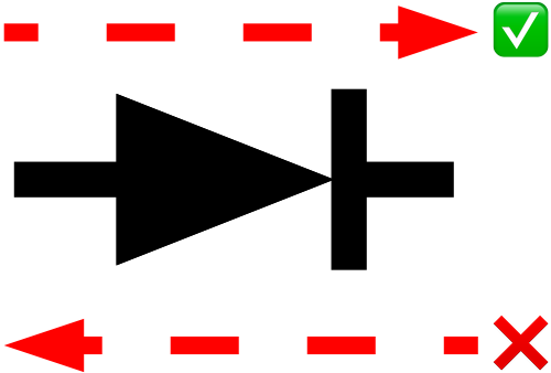
Diodes are super cool one-way valves for electricity. In one direction they will let current flow, but in the other direction the current is stopped. Excellent for ensuring that you don’t inadvertantly provide extra power that you don’t want to.
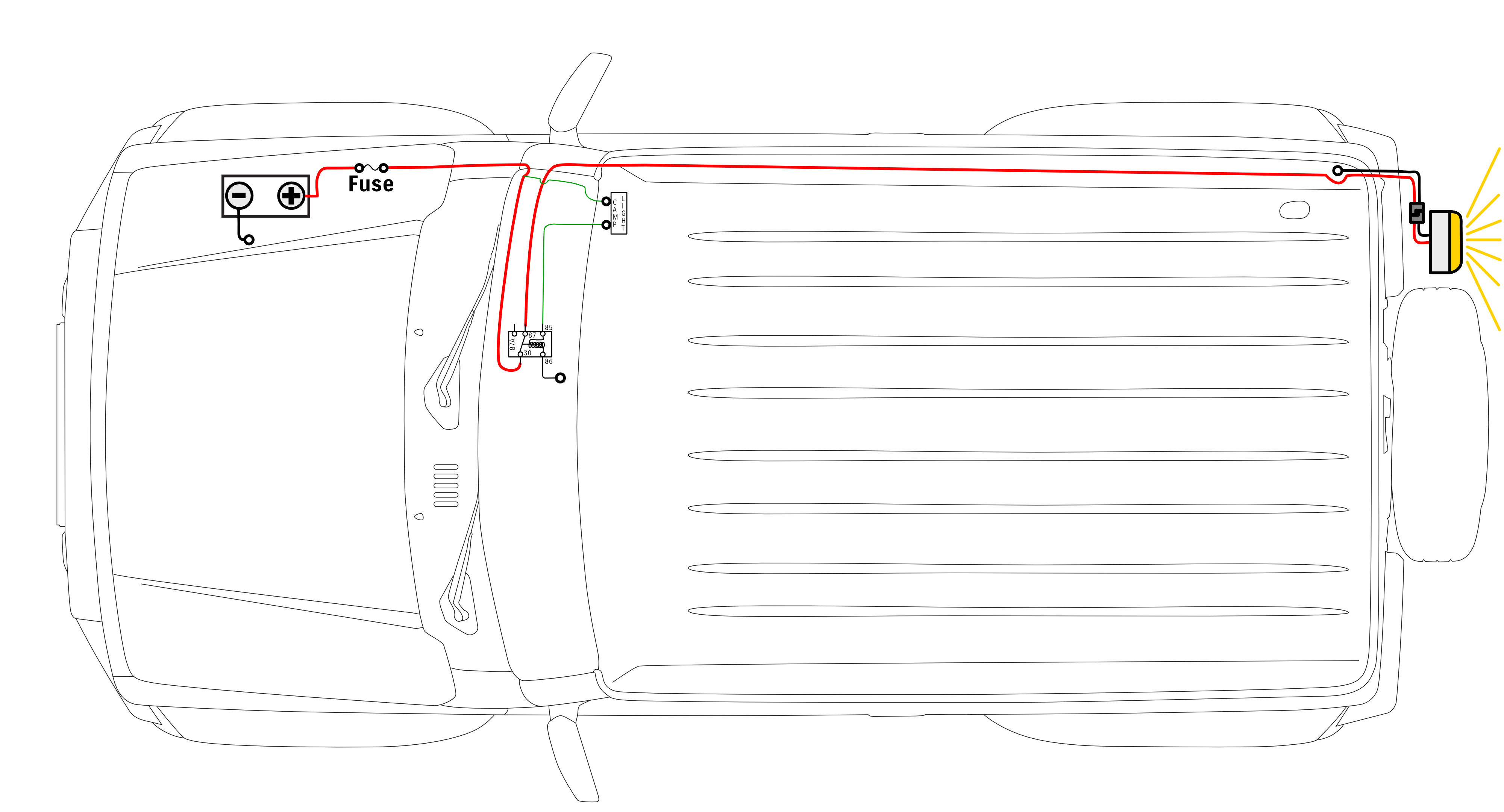
Worked example 1: rear camp light
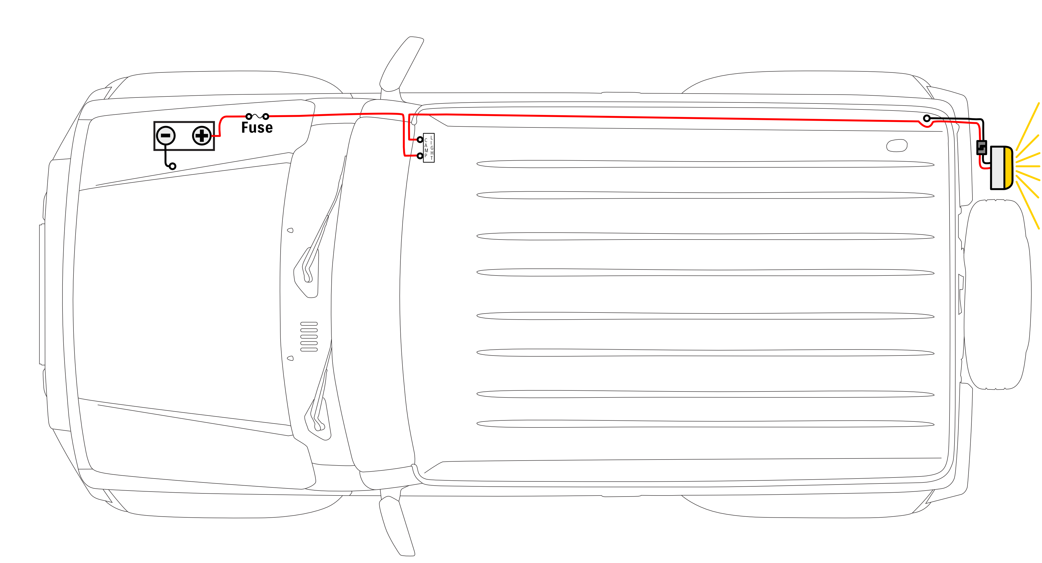
For my first hypothetical, let’s say you want to connect a rear spotlight to work as an ultra bright camp light on the back of the Jimny. It comes with its own connector for the back of the car, so you just throw some appropriately thick wire for its current rating along the car from the battery. The wires run back inside the back door and connect to an earth point just on the inside of the rear trim, completing the circuit. Because of how you’ve run the wiring, there is a connector on the outside of the car with the wiring coming from the battery via the inside of the car.
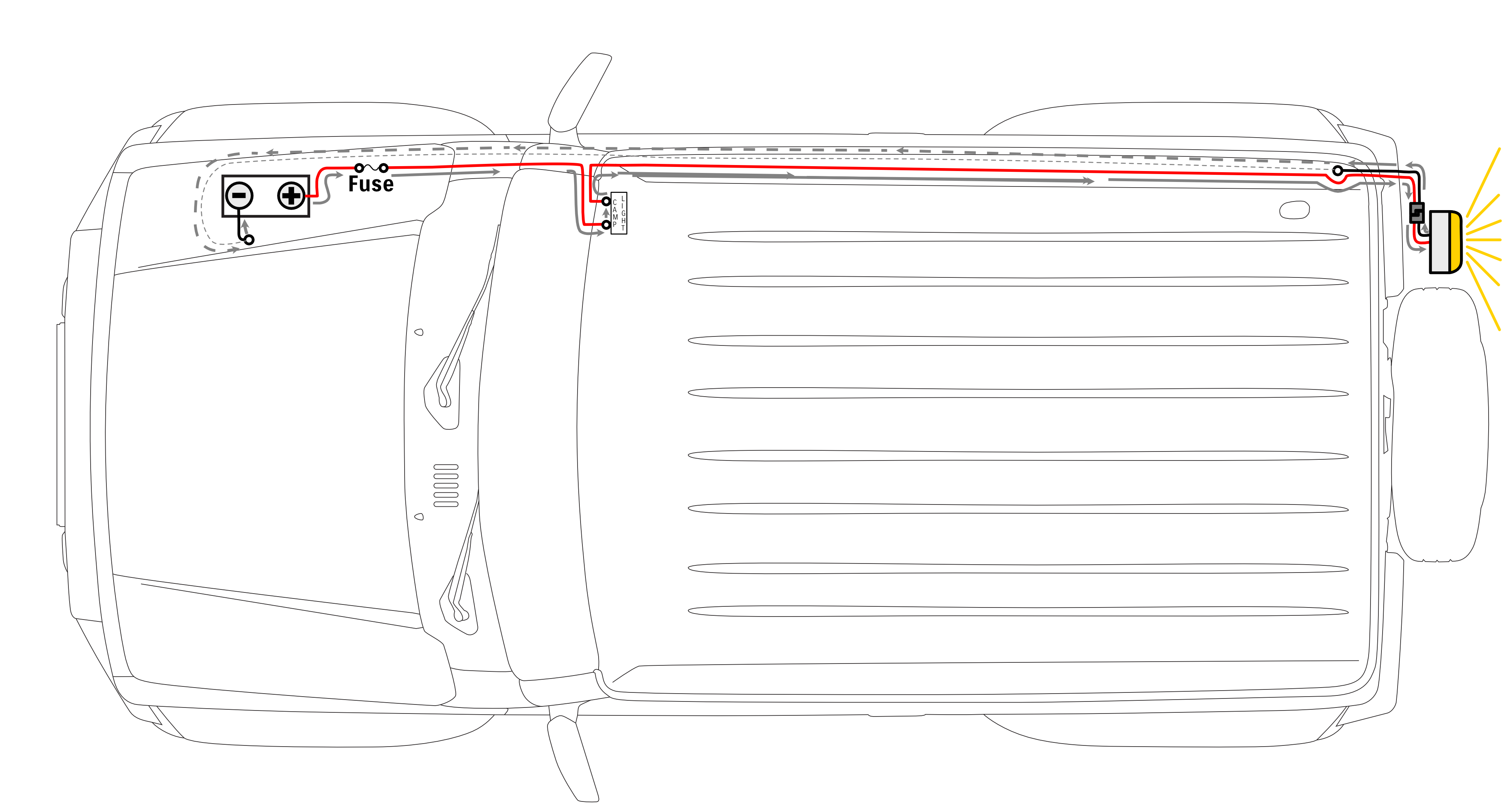
Direct connection
As mentioned, if you just plug the wiring connector in at the back of the car then the light will light up. The grey arrows show the current flow from the battery, through the light and back to the battery. I have drawn them as dashed grey arrows when the current is flowing along the chassis as part of the entire chassis/body being earthed to negative.
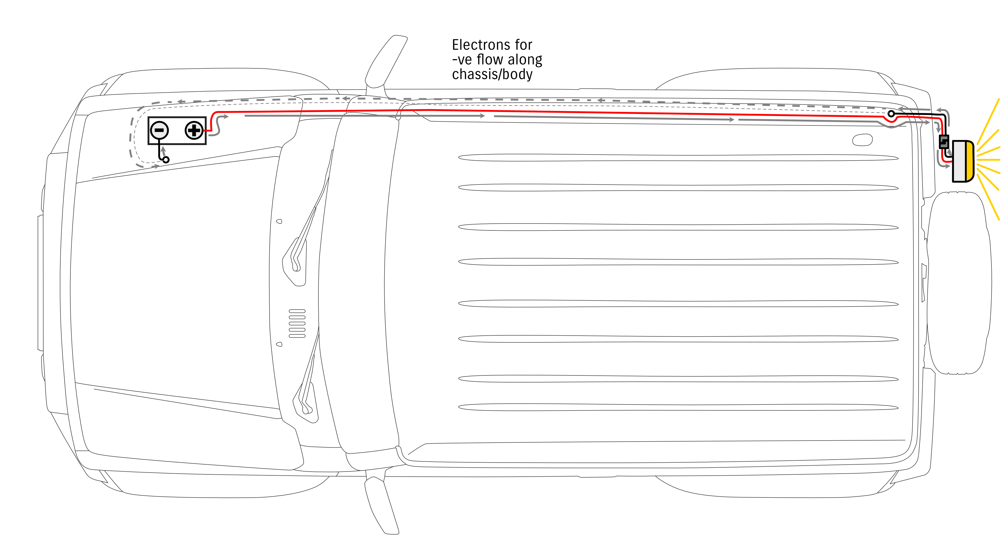
If you unplug the connector then the light turns off. While there is still current all the way along the red wire to the connector, the circuit is not completed and so the light doesn’t light up and current doesn’t return to the battery via the ground wiring.
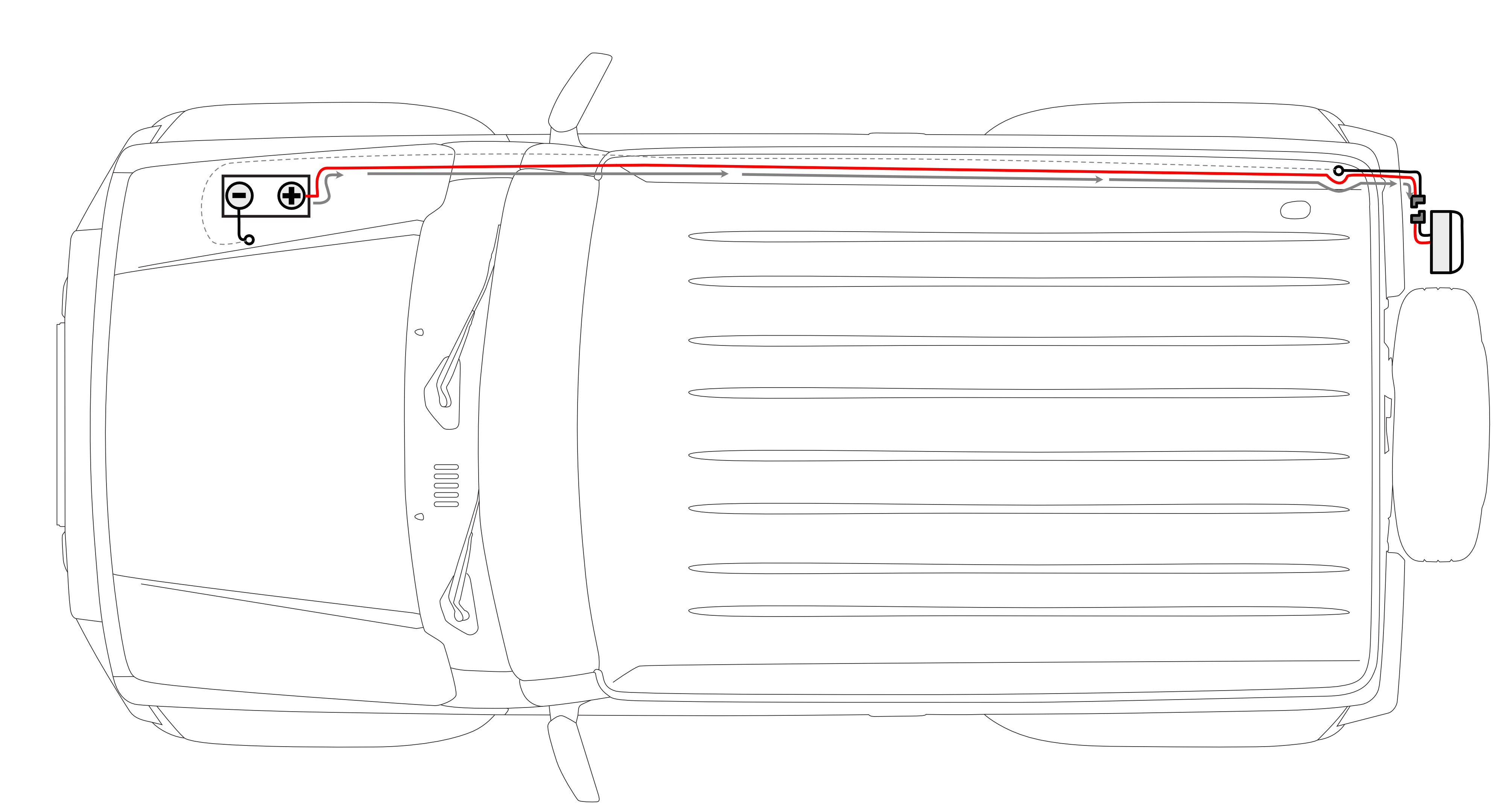
Something’s missing from how most wiring should be done, though, noting that the red wire has battery positive voltage available all along it until it reaches the connector.
Adding a fuse
What’s missing is a fuse, which will protect the wiring from ‘shorting’ out against the body of the car or the chassis all the way along the run from the fuse. When this happens it is called a short circuit as the power would bypass the device it is meant to power and would return straight to the battery, pulling large amounts of current along the wiring and melting it.
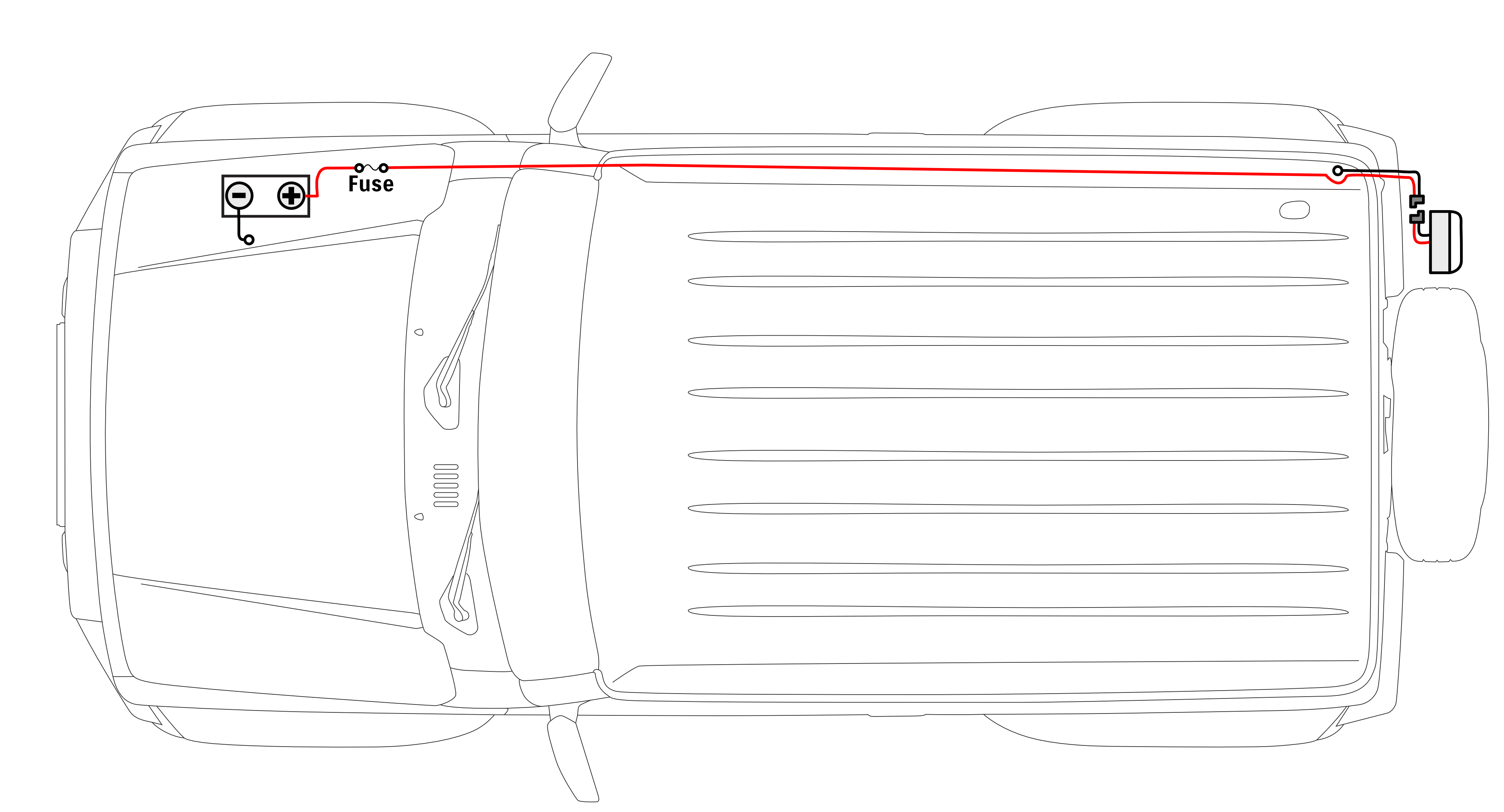
We now can still plug the connector in and have the light switch on, there’s no difference there.
The difference with this layout is the wiring is protected from shorting out and melting because of the fuse. (This fuse needs to be of sufficient capacity for the device, and the wiring needs to be thick enough to support that current too. We’ll get to the current capacity needed in a bit). Obviously it gets a bit annoying to manually plug and unplug the connector like this to turn it off or on as required, so most people would want this to be wired up via a switch.
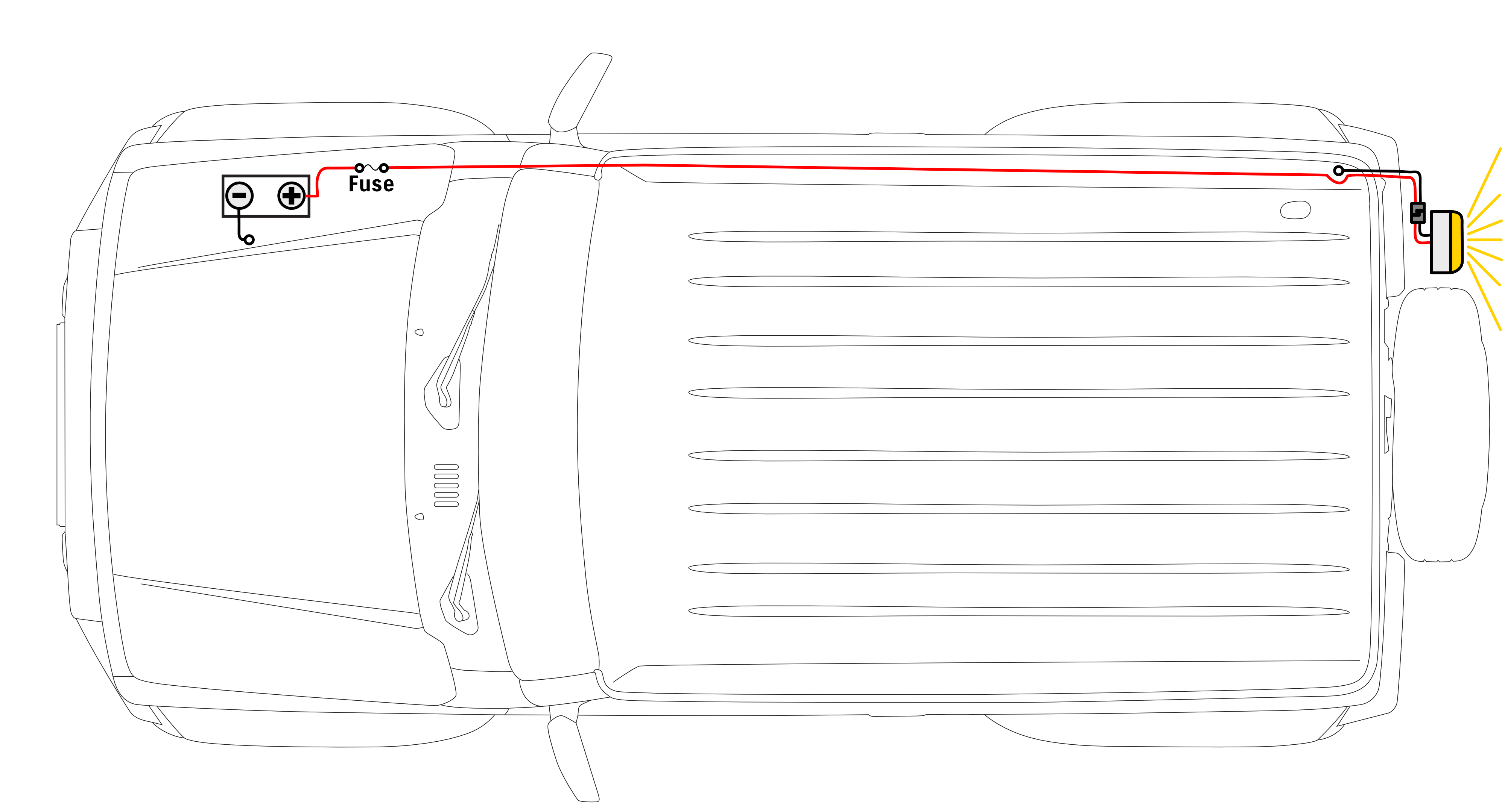
Switching it with a dashboard switch
The next stage would be to switch it via a switch somewhere in or outside the car so you don’t have to manually plug and unplug it each time. A common place would be the dashboard cutouts for accessory switches. Here you’d put some power from the permanent power line into the switch, and then the output from the switch would connect to the wiring going to the back of the car and the light. I’ve drawn this all in red to help illustrate that connection, but note your switch probably uses different colours for its input and output wiring.
Note that the light isn’t on, that’s because the switch isn’t pressed. If you press the switch on it links together the input and the output wiring inside the switch body.
We can also look at the current flow. Note that this arrangement means the current through the switch is equal to the current that the light needs when you have it wired like this.
The current flow aspect brings us neatly to a limitation with this arrangement. Let’s say for some reason you wanted a high powered spotlight as your camp light and it draws 10A from the battery as it is a 120W spot light (120W = 10A * 12V). Most of the small dash switches are rated for 3-5A maximum current draw (36 – 60W maximum power). Clearly the switch cannot handle the power of this spot light so you need to combine it with a relay to not overload the switch.
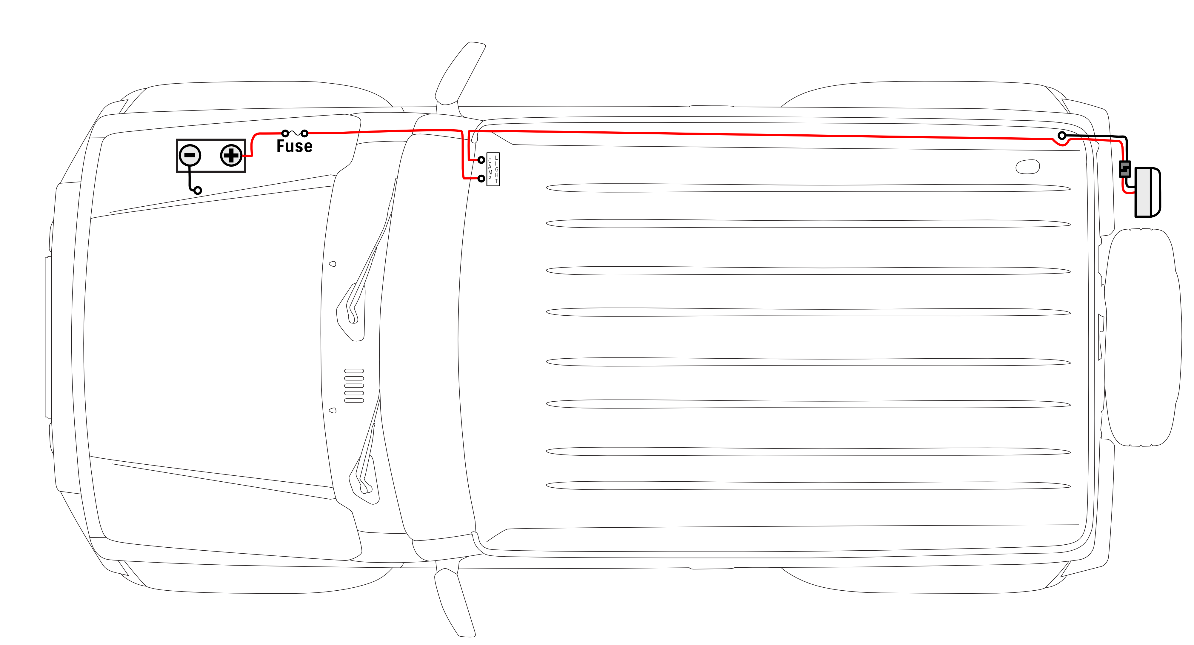
Switching it via a relay
Relays definitely cause a lot of confusion about how to wire them or even what they do, so hopefully building up a wiring diagram helps build up your understanding from first principles. As per the description of a relay above I’ve used the standard relay wiring pin numbers.
With the wiring arranged so battery positive goes to the relay on pin 30, the light positive feed comes from pin 87, and the switch takes a battery positive input and gives an output to pin 86, with pin 85 connected to ground, we end up with something like this.
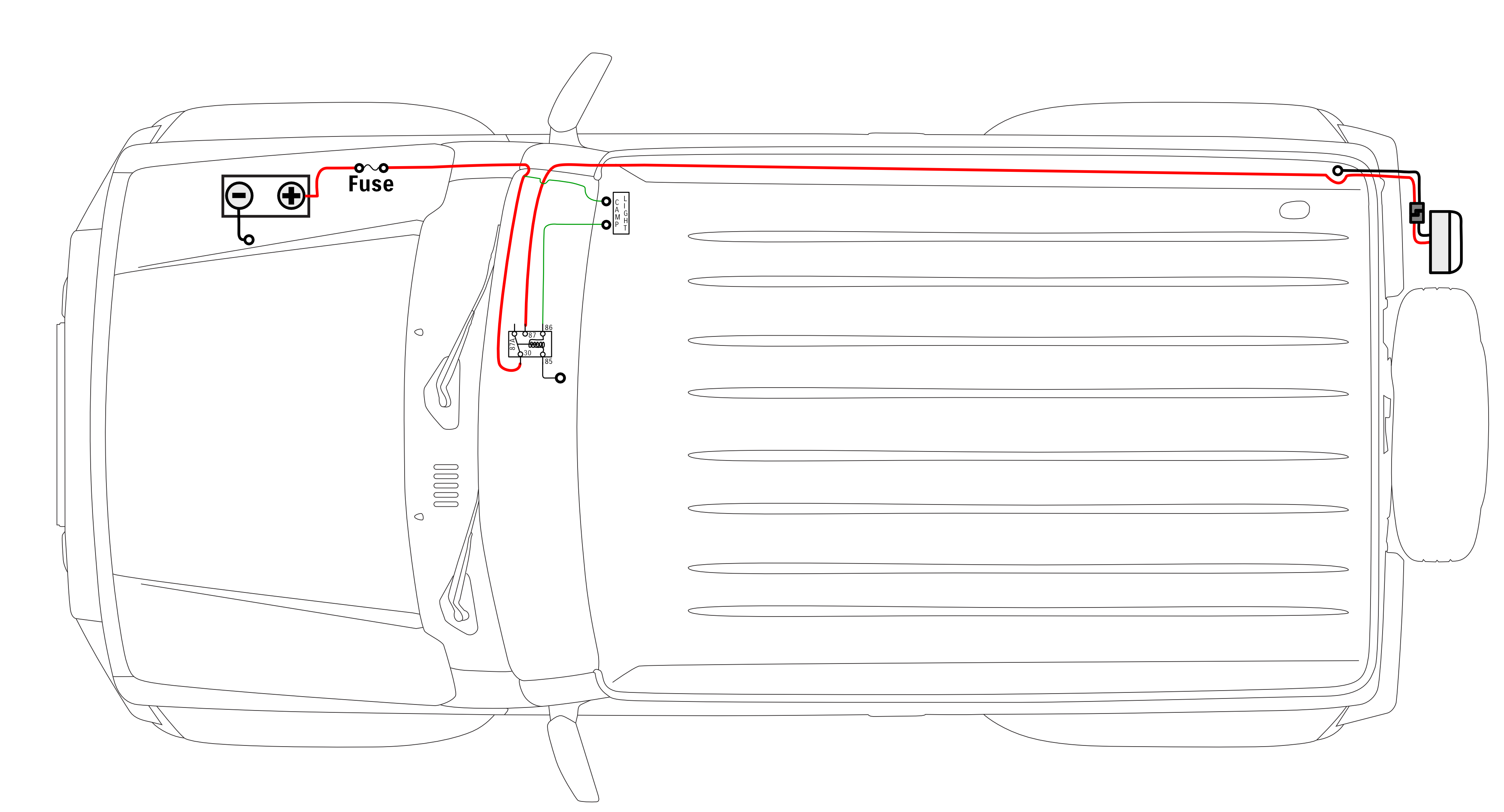
Note that I have drawn the switch with thinner wire than before. This is deliberate: the switch requires much thinner wiring now that it is transmitting only a tiny amount of current to the switching side of the relay. That switching side as I have drawn goes to a little electromagnetic coil; when the dashboard switch is pressed and current flows to the relay, that energy pulls the switched side of the relay to direct power from pin 30 through to pin 87. Note that when the relay is not energised, power has the possibility to flow from pin 30 to pin 87a, though nothing is connected to that pin in this scenario.
I’ve also drawn the current paths on this so you can understand how electricity is flowing; the thinner arrows for the switching side of the relay and the dash switch indicates the lower current flow through that circuit.
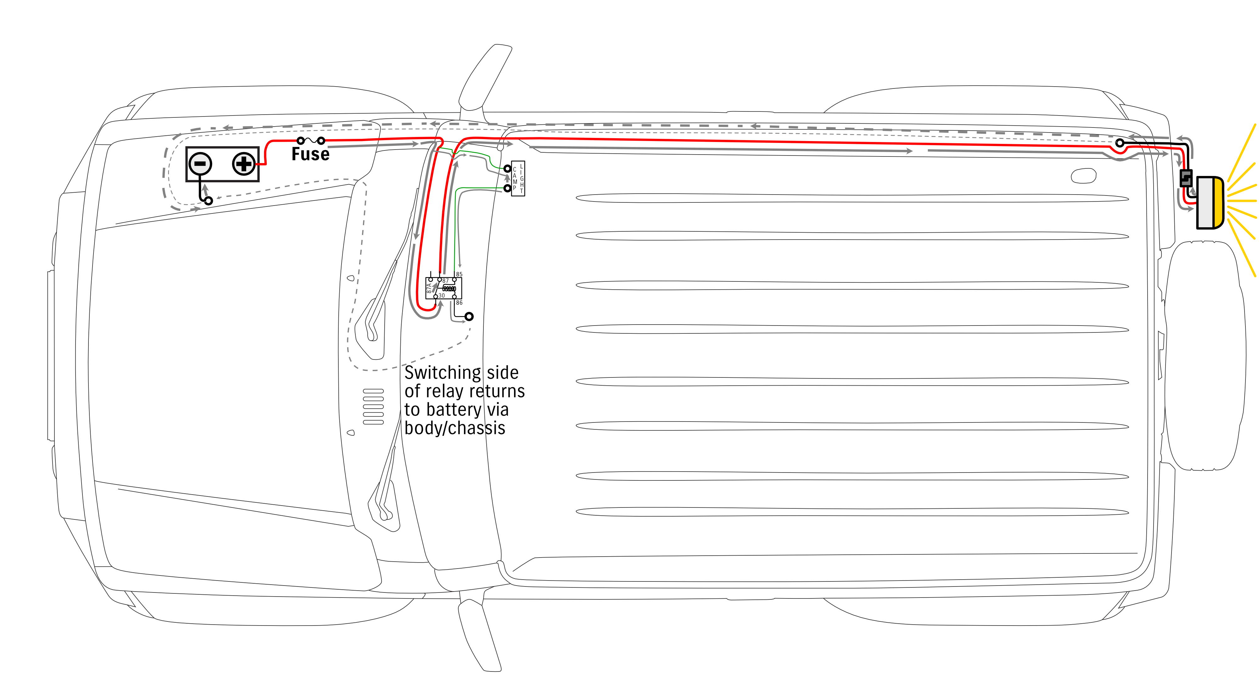
Starts to get super messy if you keep drawing the current paths so I’ll also show you what that looks like without all the grey arrows.
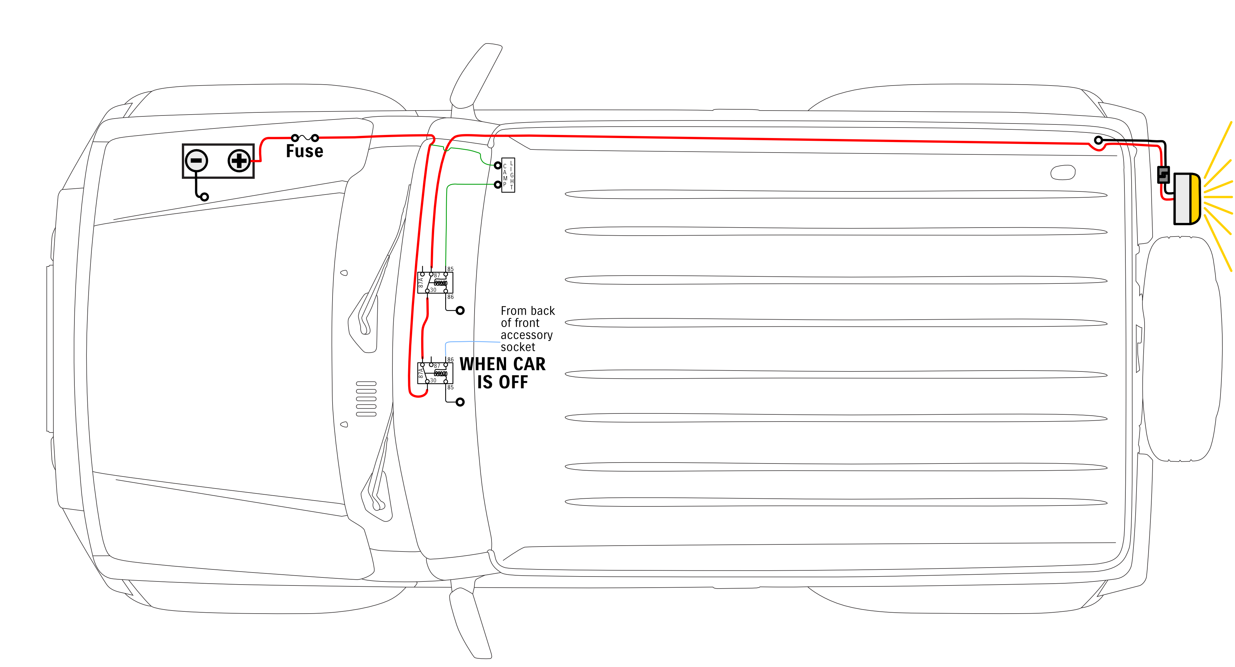
Now that’s all well and good, however, let’s say you want to make it foolproof so you cannot have these lights on when driving. There’s a few ways you can achieve this, even with just a single relay, but I’m going to illustrate how to use a 2nd relay to provide power to the light only if the ignition of the car is off. I’m doing it this way as it will give you more versatility if it was more than just this light you wanted to isolate as only able to come on when the car was not running.
Switching it via a relay, but only when the car is turned off
Remember I said how a 5 pin relay has a pin that is connected when the relay is not energised? Well, that would be one route to provide power into the light’s relay only when the car is not on. This is what that wiring would look like, with the car turned off but the dash switch not pressed.
The light blue wire I have going into the car on/off relay is just from the back of the cigarette lighter socket. This wire receives power when the car is put into the accessories or the on position, so we want the light to only be on when this wire does not have power.

See how the wiring out of the first relay is connected to pin 87a on that relay, and following through that path while it provides power into the 2nd relay, the switch not being pressed means the 2nd relay is not energised and so there’s no way for battery power to make it all the way to the light at the back of the car.
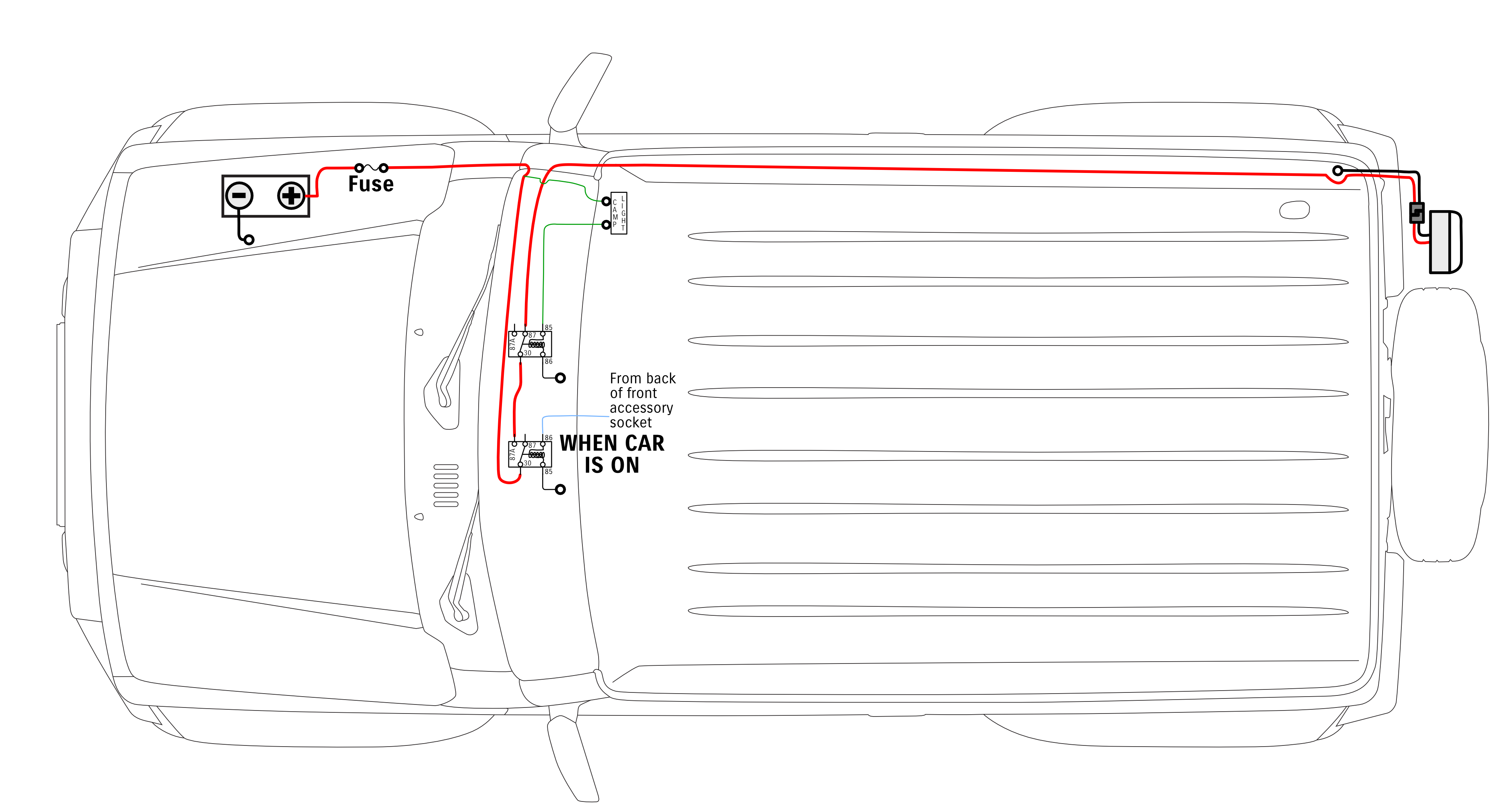
If, on the other hand, we press the dashboard switch and energise this 2nd relay then now current can flow from its input pin 30 out to its pin 87 and out to the light, turning it on all while the car’s ignition is on.
Now if we turn the car on then now there will be now connection between pin 30 and pin 87a on the first relay. With no power feeding into the 2nd relay, even with the switch pushed the light will not be on and you won’t be at risk of blinding someone behind you while you drive.
Worked example 2: switchable high current auxiliary power connection to rear
A common issue for people in the Jimny is how the front and rear auxiliary power connectors are joined together. Both these sockets are rated for 10A (=120W of power draw) spread across both sockets.
If you want a bunch of power available in the back of your Jimny, say for an elaborate camping 12V setup, then you’ll want to do something else to provide you power.
Direct connection
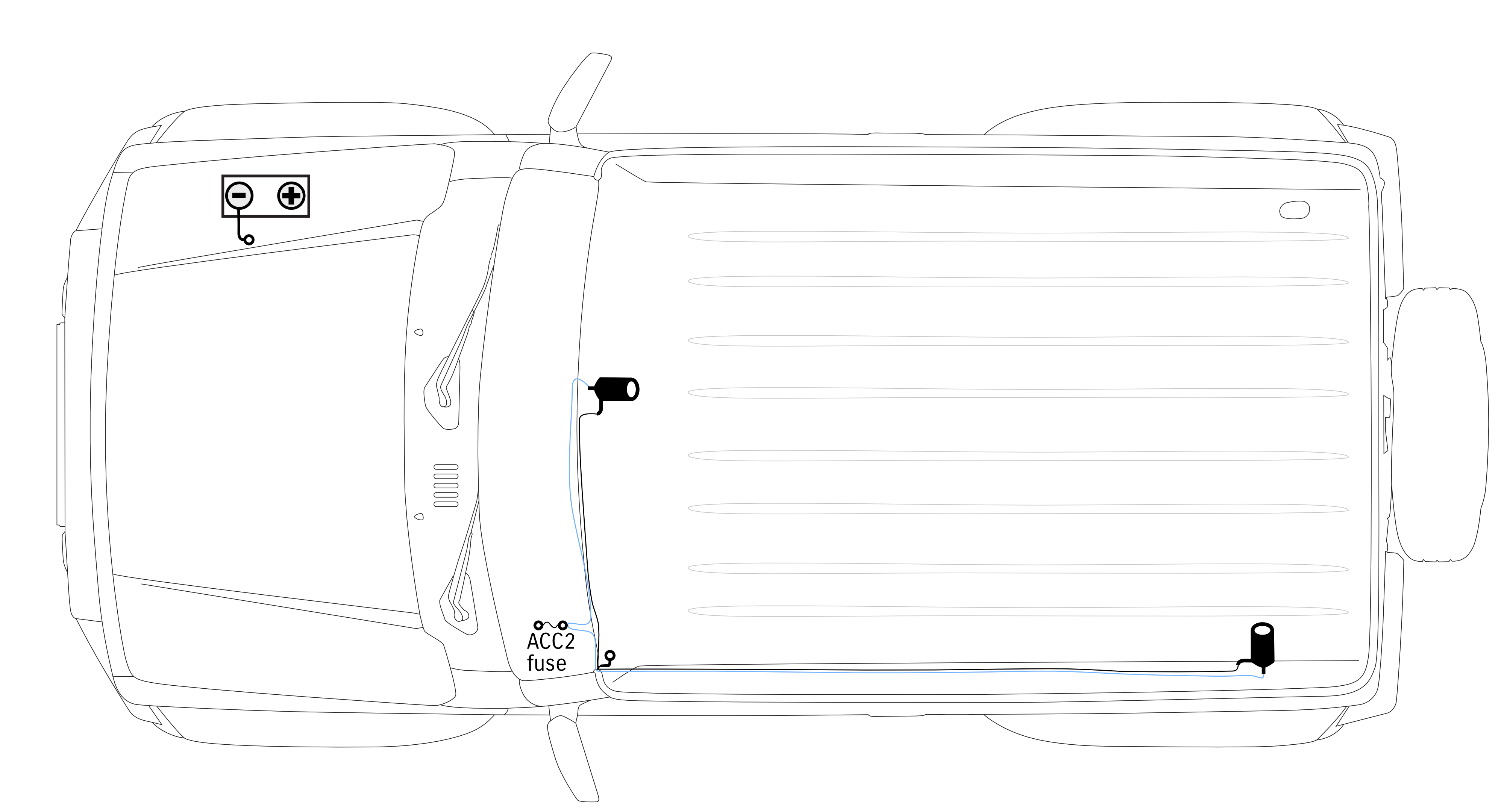
You could just run a big fat cable (e.g. an 8AWG cable = 50-70A current available) to the back and hook it up to a power panel with a couple of Anderson connectors & some USB ports on it. At this point it’s totally separate to the rear accessory sockets with how this is wired.
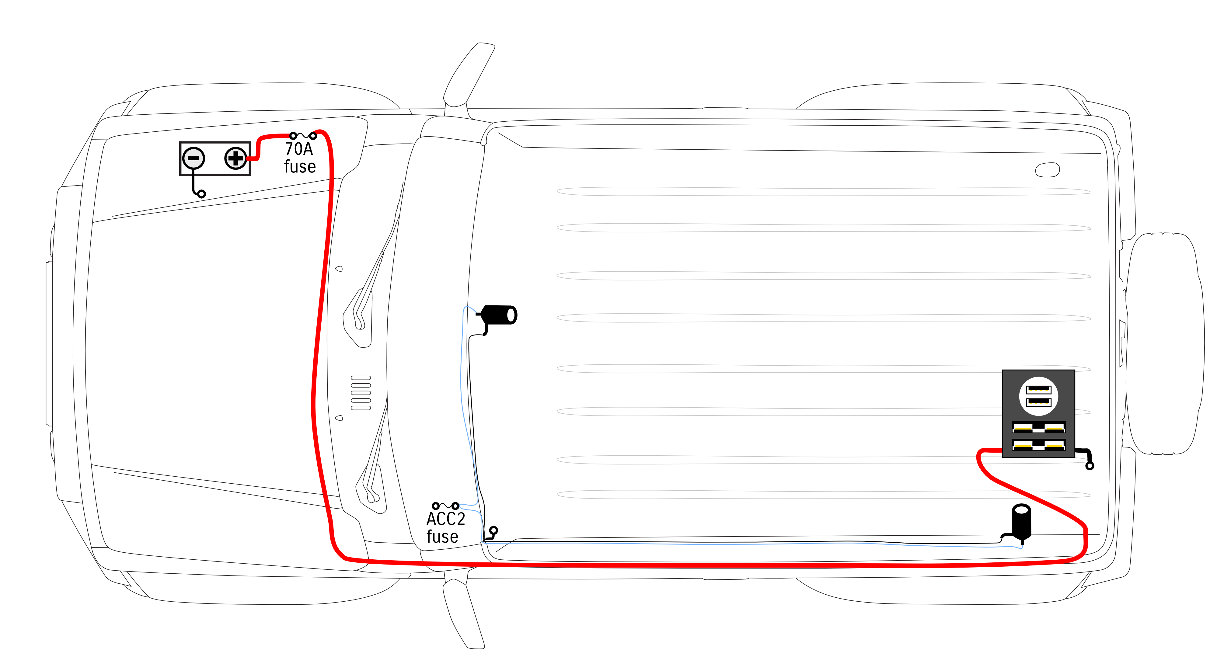
Let’s say, however, you want to make this emulate how the factory rear socket works so it only has power when the key is on.
Using a relay to switch a rear accessory panel
50-70A current draw is well beyond any switch you can put in let alone the car’s ignition switch, so this is a perfect job for a relay. The input to this relay would be the standard cigarette lighter socket wiring as it’s a) got sufficient rating to do the job and b) provides power only when the car is on. You just need to get some triggering power for the relay out of the +ve side of the rear accessory socket, and you can use the -ve side to the rear accessory socket to provide the earth path for the negative side of the switching part of the relay.
With the car off it looks like this:
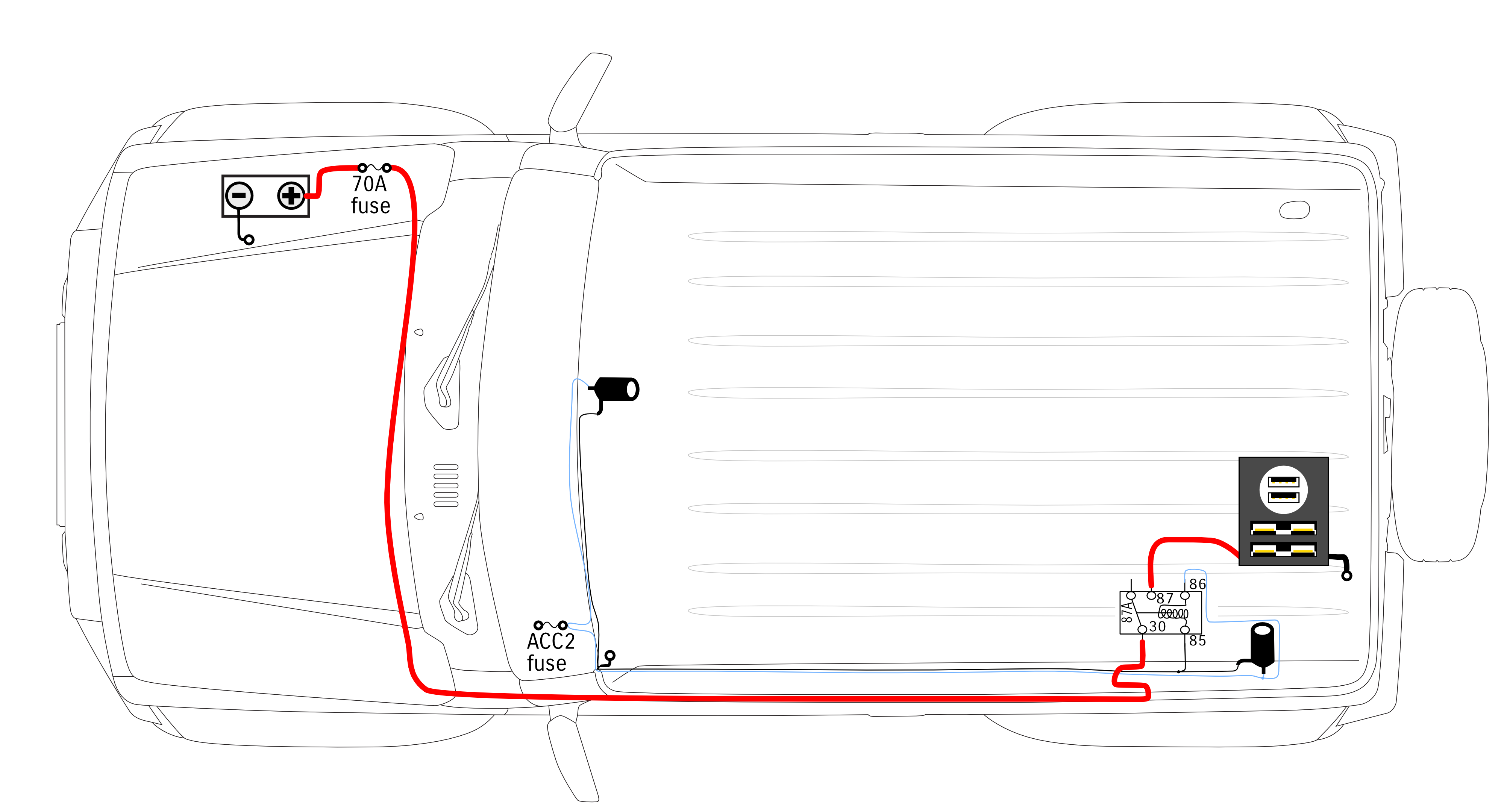
This is great for ensuring that you can’t drain the battery because it’ll only have power at the back when the car is on, but it can also draw a big amount of power if needed.
Once the car is turned on, the relay will be energised on the switching side and this will connect the accessory panel power input to the high current/switched side of the relay, making your new accessory panel work just like the standard accessory socket does.

You’ll also not be overloading the accessory socket wiring either, and they’ll continue to function as normal. Now what about an option that gives you the ability to switch the power on or off at will?
Triggering the relay via a switch or the car being on
The above version works like standard now we’ve added the relay: i.e. the auxiliary power we’ve added at the back only has power when the car is on. It would also be possible to add a switch to the dashboard which, if its input is given permanent power, will allow you to energise the relay at the back and turn on your high power accessory panel whenever you want. If you tap this into the input wire of the switching side of the relay alongside the power from the factory accessory socket then it’ll still come on when the car is on, or when you have pressed the dashboard switch.
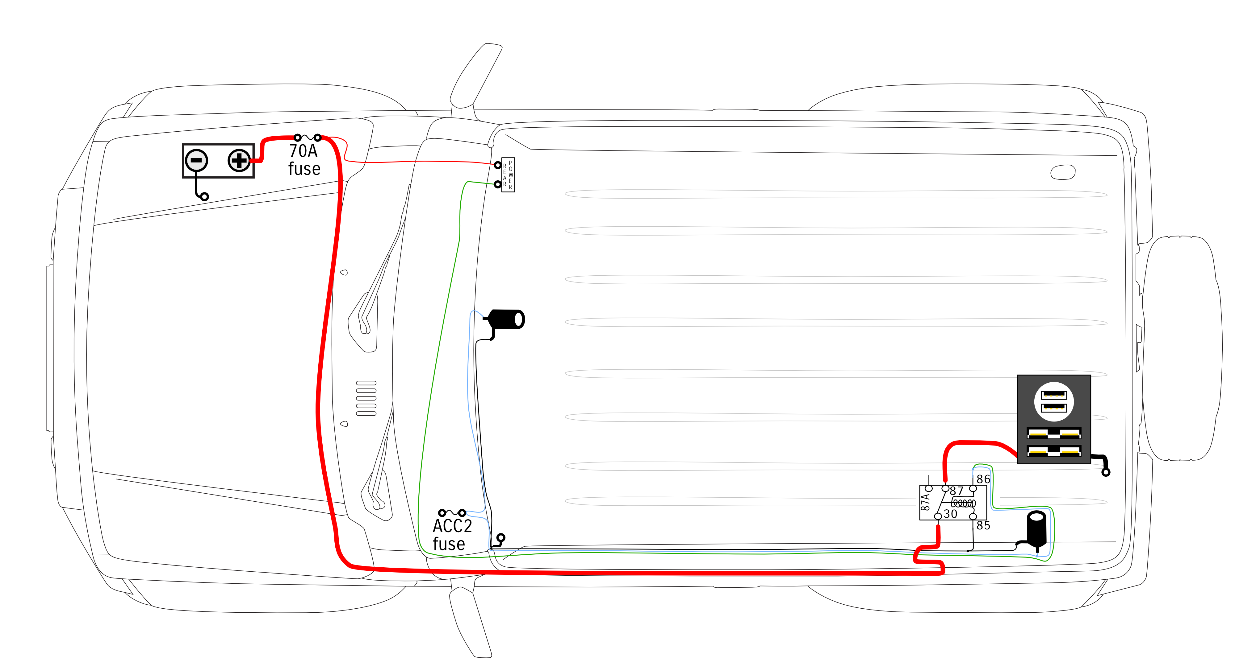
There is a drawback to wiring up the system like this. Now, when you press the switch look at what happens to the current through the switch: it also energises other stuff on the light blue wire to the car’s wiring harness. Because the ACC2 fuse is also connected to the switched power input to the stereo, this will also turn the stereo on when you press the switch and the car is on. Probably not what you were after…
There’s nothing particularly bad here, electrically, mind you. However note that if you have 10A of draw off the front (or rear) factory accessory socket(s) then all of that 10A will be coming through the switch’s wiring when the car is off. Not good given most switches for the dash won’t be rated for that current. What you really need is a way to tell the wire from the switch to only put power into the relay and not to energise the rest of the car’s wiring.
Using diodes to avoid backfeeding
Enter our magical one-way valve for electrons: the diode. If you fit a diode to the line coming from the standard auxiliary socket’s wiring so power can flow from that wire, but not back to it, when you energise the switch no power will go to the front auxiliary socket. The simple addition of a diode will stop current going all the way back down the entire light blue accessory 12v wiring in the car.

It’s that simple: quick use of a diode and now we can have the rear accessories either permanently powered if we press a switch or only turned on when the car is on. This is an excellent way to have higher powered 12V accessories just using your factory battery and allow you to only be on either with the car or when you want them to be.
Worked example 3: Independent power sources depending on car state
This example is for someone who wants to use a cheap 2nd battery of relatively low capacity, potentially without the complexity of adding an expensive DC-DC charge controller.
What you want to do is not have accessories draw off the 2nd battery when the car is running but instead draw directly from the car’s charging system/1st battery, and when the car is stopped you’re happy for accessories to draw off your 2nd battery which you might do something like only charge via solar or something to help top it up.
Triggering power source changeover when car is turned on
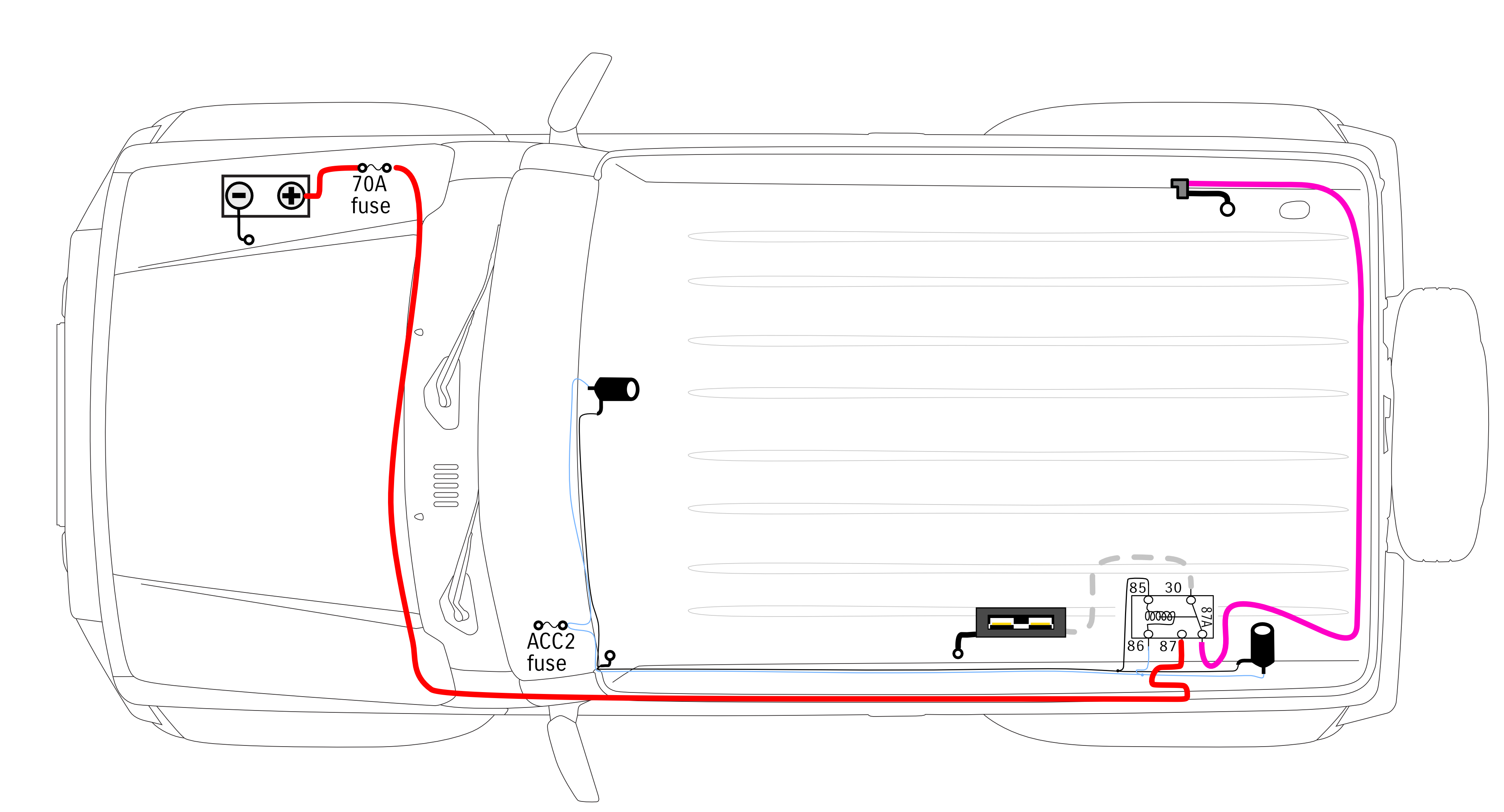
To do this you need a 5 pin relay, and you make your accessory power come out of pin 30 on the relay. The car’s main battery would provide power into pin 87, and the 2nd battery +ve would go into pin 87a on the relay. Taking a key-switched input to the switching side of the relay this will mean it switches over power source according to if the key is on or off.
If the car is off, then the power will get sourced from the second battery. I’ve shown this here by changing the colours of the wiring from the different power sources & colouring the power into an accessory panel with the colour of the source powered. Also note I’ve flipped the relay around from the way it’s been depicted before, this is purely to make my job drawing the wiring easier!
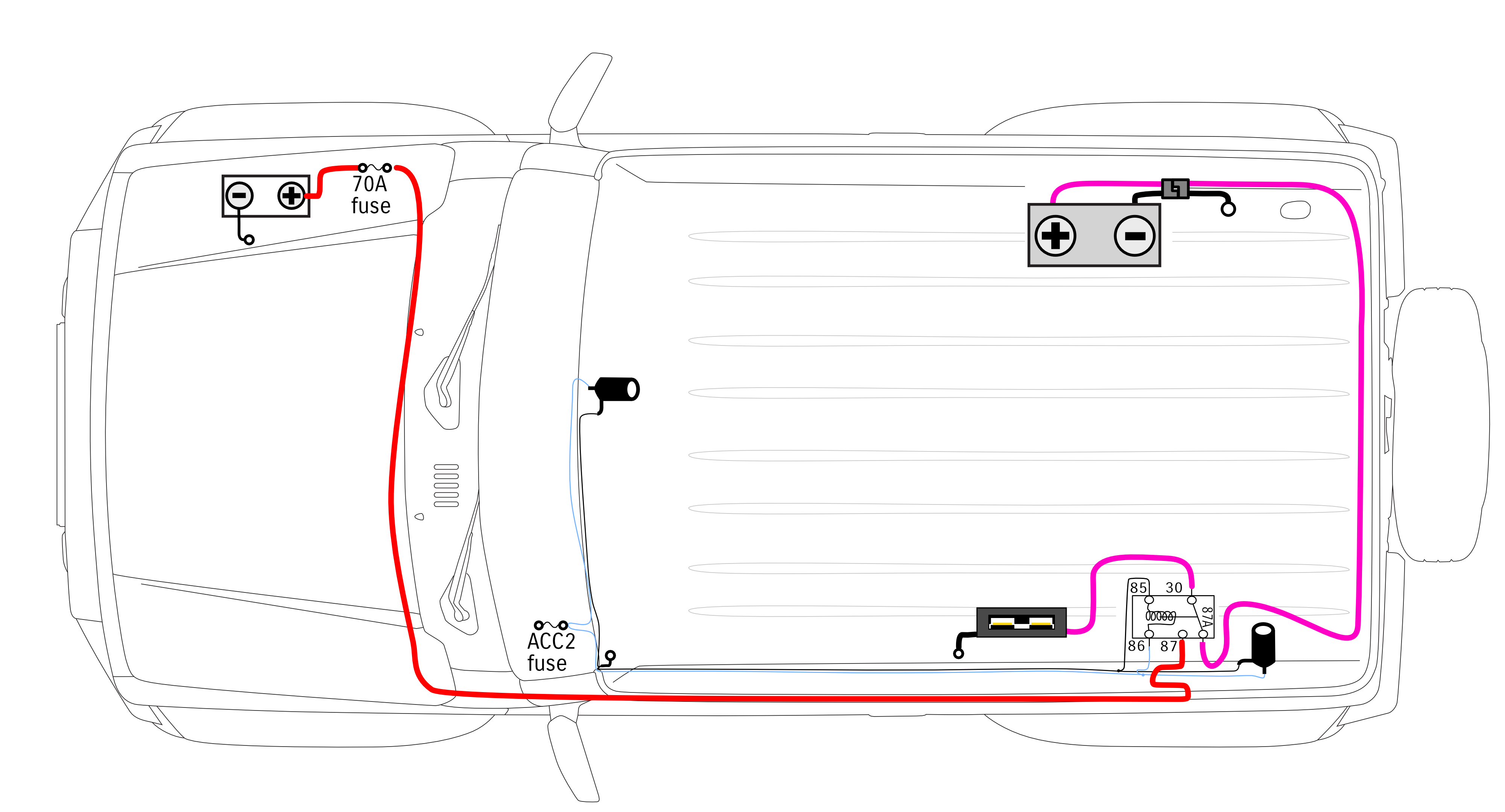
If we turn the car on then the power will be sourced from the car’s battery, as the relay will get energised by the factory accessory socket circuit.
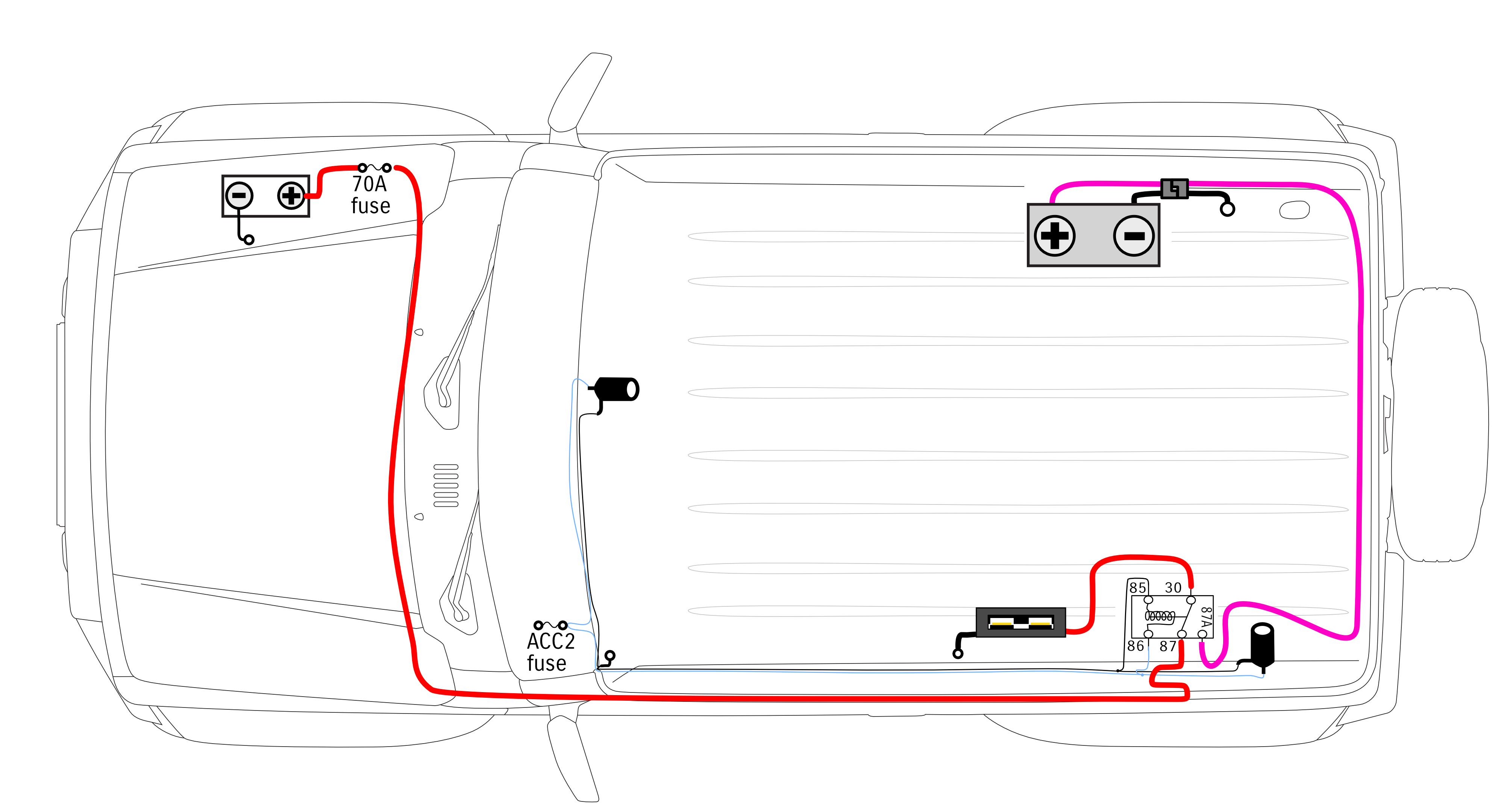
Such an arrangement means you only need one connector to your accessories – they are not aware they’re seeing different power sources when the relay switches over – and you just need to make sure that both the 2nd battery and the car’s battery share earth points to simplify the wiring (or you need a double throwing relay i.e. you do changeover for both +ve and -ve terminals on the 2nd battery).
If you don’t have the 2nd battery in the car and you turn the car off then there’s no power that will flow to the added accessory panel here, so they can’t draw off the car’s main battery with the car off.
This sort of arrangement is common especially for using standalone batteries or where people want to just charge simply via solar. It saves the auxiliary battery getting too drained, which means you never fully drain the auxiliary battery, so long as you drive enough. It also limits the strain on the car’s charging system which is not having to fully recharge an almost discharged 2nd battery once you start the car, and, if you’re on a budget this would be how you can avoid needing to do a charge controller at all.