
Understanding Jimny hyperflashing indicators
One of the issues that crops up with people replacing indicator bulbs in generation 4 Jimnys is the ‘hyperflashing of the indicators’. This page is a bit of a deep dive as I document trying to understand it, and actually give useful advice on it.
Part of the difficulty is that people don’t really understand electrical theory; I’m not necessarily saying people have to, but this page might increase your understanding of Ohms law and how it works with lighting upgrades.
Why it arises
Hyperflashing is essentially a former symptom of failure that has now become a feature to alert drivers to a failure in the indicator circuit.
In Australia, indicators are governed by Australian Design Rule 13/00. For standard operation, the frequency is required to be between once a second (60 times a minute) and twice a second (120 times a minute):
The light shall be a flashing light flashing 90 ± 30 times per minute.
However, failure is also specified:
In the event of failure, other than short circuit, of one direction-indicator lamp, the others shall continue to flash, but the frequency in this condition may be different from that prescribed.
You might well ask why this is specified: well, older cars used a separate ‘flasher relay’. These flasher relays built up current, then released it, and continued to do this to provide a steady flash. Because of how those relays work, they would change frequency based on load: not normally an issue, but if you blew a globe in a circuit then they would flash faster (with lower load). Related to this: indicators click because they used to be a physical clicking relay, and now the audible click of indicators is required!
The behaviour of a change in flash rate, effectively originally a side effect, is now a requirement to alert you to an issue with the indicators:
Operating tell-tale mandatory for direction-indicator lamps of categories 1, 1a, 1b, 2a and 2b. It may be visual or auditory or both. If it is visual, it shall be a flashing light which, at least in the event of the malfunction of any of these direction-indicator lamps, is either extinguished, or remains alight without flashing, or shows a marked change of frequency. If it is entirely auditory it shall be clearly audible and shall show a marked change of frequency, at least in the event of the malfunction of any of these direction-indicator lamps.
More modern vehicles do not use a flasher relay, and the 4th generation Jimny is no exception. Instead of a traditional flasher relay, the body control module does the indicator flashing itself using solid state relays/switching devices. Solid state flashers are great as they do not change frequency due to load: this is why you might have heard of ‘LED flasher relays’ before for indicators.
To emulate the behaviour of the older style relays to alert drivers to failures of globes in the indicator circuit, the Jimny (and indeed most cars using a BCM based indicator system, or solid state relays) monitors the current drawn by the indicator circuit.
Essentially, the different power drawn by the various indicator globes is a known design choice: this current, minus some tolerance to allow for differences in wire resistances and globe tolerances, is looked at. If everything is normal then flash at the normal speed; if there is less current being drawn then we can assume a globe is blown and flash faster to alert the driver that people might not know what direction they are intending to go in.
This is all well and good for using the standard globes, but LED replacement globes exist. They draw significantly less power for the same light output, so they produce less load on the indicator circuit. Go too far below the expected current draw and the car will assume there is a blown globe and flash the indicators too fast.
Standard Jimny indicator load and resistance
We first start off by understanding the Jimny’s indicator load. There are 3 globes in play per side:
- Front indicator globe: 21W
- Side indicator repeater: 5W
- Rear indicator globe: 21W
The front and rear indicators hook into different parts of the BCM: something I’m yet to fully determine is if they are internally linked together or separately monitored. This will become important when we work out how to emulate the load of the factory globes.
Here’s the wiring of the indicator circuits, with the related connectors indicated. Note that the front and rear indicators come out of different connectors of the BCM. Both are in the front facing part of the BCM, the rears come out of the lower 32 pin connector and the middle 24 pin connector has the connections for the front and side indicators.
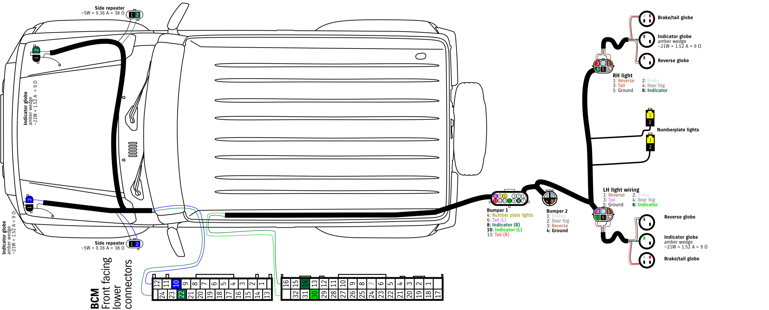
To calculate the current drawn by these globes, we can use the fact the current drawn is the power divided by the voltage. A car is nominally 12V, but when running is more like 13.8V, so for precision, theoretically:
- Front or rear indicator bulbs each draw 21 / 13.8 = 1.52 A
- Side indicator bulb per side draws 5 / 13.8 = 0.36 A
Another way to look at this is the resistance that each bulb presents to the circuit. We’ll actually cover what resistors are in a minute, but for now just trust me a bit. Using Ohms Law where resistance = voltage / current, we get:
- Front or rear indicator bulbs each are 13.8 / 1.52 = 9.08 Ω
- Side indicator bulb per side draws 13.8 / 0.36 = 38.3 Ω
That isn’t quite good enough for me though, I also went through and measured by stock bulbs in terms of the current drawn & hence implied resistances with the bulb lit up, and I got:
- Front or rear indicator bulbs each draw ~1.84 A i.e. their illuminated resistances are 7.5 Ω
- Side indicator bulbs each 0.30 A i.e. illuminated resistance is 46 Ω
Basically this means the combined draw for the front is somewhere between ~1.8 A and 2.2 A and rear is 1.5 to 1.8 A give or take a bit. As a circuit, showing the current flows, it looks a bit like this:
Before someone gives me grief, I’ve drawn the current flows the way people think of it, i.e. from positive to negatively. Physics tells us that it’s electrons flowing from the negative to the positive so this current flow is, effectively, backwards but for our purposes this doesn’t matter so much.
This current draw is the target to emulate with LED bulbs.
What about the draw from LED bulbs?
I tested a couple of different LED options:
- Replacement front indicator assemblies drew 0.25 A at 13.8V, so are 55.2 Ω resistance
- Side indicator LED replacement units drew 0.07 A at 13.8 V, i.e. 197 Ω
- Replacement rear taillight assemblies without integrated resistors drew TBA
In addition, my car has an ARB bullbar with additional front indicators in the bullbar:
- ARB bullbar indicator current draw 0.28 A at 13.8V, i.e. 49.3 Ω
This matches the 4.7 W marked on the light
Finally, I also have a factory Suzuki towbar wiring assembly. I have to assume its relays draw negligible amounts if a trailer is not hooked up to it, they would be rather crap relays if they did. Part of the point of these trailer wiring harnesses is to separate the trailer load from the car’s indicator circuit load, too, so it does not really need to be considered further.
How to mitigate against hyperflashing if you’re upgrading to LED indicators?
The standard way of doing this is to integrate resistors into the circuit. Resistors in parallel with a load act as ‘current dividers’. The inverse total resistance that the circuit sees is the sum of the inverse resistances for all resistors in parallel, so you can’t just simply add up resistance values to calculate what is needed.
Resistance is (not totally) futile
First off, what is an electrical resistor? It’s something that resists the flow of electricity. No resistance between positive and negative in an electrical circuit is called a short circuit: without a fuse to stop the flow of current, in theory a short circuit can flow up to infinite current. The higher the resistance on a circuit, the less current flows through it: that’s (sort of) the idea that electricity ‘follows the path of least resistance’. (It’s a bit more complicated than that: electricity flows proportional to resistance, so if you have multiple paths more will go via the path with lower resistance, but some will flow on the path with higher resistance, too).
There are two ways to connect up a resistor into a circuit: you can connect it in series, or you can connect it in parallel. In series just means that the resistor is ‘along’ a path of current flow. Parallel means it is across the path instead. If you connect resistors in series then they divide voltage along that path, in parallel they divide current instead.
For hooking up a resistor to an LED light, you want them in parallel. One side connects to the positive side into the LED, and the other side to the negative side out from the LED. In this way the ‘effective’ resistance becomes lower, and hence more current is drawn, emulating a normal bulb. If the car has a blown globe then it would have infinite resistance and no current would flow at all, hence it induces hyperflashing.
The key element here is to understand how much resistance is needed, and where it is needed. I tested this using a fairly typical Chinese replacement front indicator assembly. In my testing, it appears that front and rear circuits are independent: having more current flowing to the rear circuit than needed did not stop the front circuit needing resistance added.
Note this test was done with my ARB indicator repeaters installed, though I also have LED side indicators (though even the standard repeaters do not draw much current).
| Load resistor (Ω) | Current through resistor (A) | Power through resistor (W) | Total current, resistor and indicators (A) | Effective resistance (Ω) | Effective bulb wattage (W) | Hyperflash? |
|---|---|---|---|---|---|---|
| 3 | 4.6 | 64 | 5.3 | 2.6 | 73 | Blew the 5A HAZ fuse, dash hyperflashed |
| 6 | 2.3 | 32 | 2.9 | 4.8 | 40 | No |
| 12 | 1.15 | 16 | 1.8 | 7.3 | 26 | No |
| 18 | 0.8 | 11 | 1.4 | 9.9 | 19 | No |
| 24 | 0.6 | 8 | 1.2 | 12 | 17 | No |
| 30 | 0.46 | 6.4 | 1.06 | 13 | 15 | Yes |
| ∞ (none) | 0 | 0 | 0.6 | 23 | 8 | Yes |
| STANDARD, THEORY | 0 | 0 | 1.88 | 7.3 | 26 | No |
| STANDARD, MEASURED | 0 | 0 | 2.14 | 6.5 | 30 | No |
As you can see from this test, you can get away with a lot higher a resistance value than most LED indicator suppliers give you. Going too much on it will produce hyperflash, but, the higher the resistance value the less power it is effectively dissipating & therefore the less heat it produces. We’ll touch on that in a bit around recommendations.
The closest to replicating stock is somewhere between a 12 Ω and little lower resistance like 9 Ω.
I repeated the test without the ARB indicator repeater hooked up, and the regular side indicator to see if there was a difference i.e. is it more or less sensitive.