
Runva 9.5XS winch install
Sections
- Intro and thoughts
- Installing into ARB bar
- Accessing the winch aperture
- Design winch adapter plate (if needed)
- Fabricate adapter plate (if needed)
- Prep and make plate look fancy (if needed)
- Installation of winch
- Hinged number plate mount
- Electrical stuff
- Control unit installation
- Switches – in-cab islolation and winch control
- In-cab winch control
- Adapting wireless controls
Intro and thoughts
With a Jimny being a relatively light car, a lightish winch is acceptable and you don’t need a 12,000 lb pull or similar. There’s a couple of options here, namely you can go ATV or very small winches (3000 – 4500 lb; 1300 – 2050 kg) or you can go some of the mid pull winches (usually under 10,000 lb; 4500 kg).
One disadvantage of the really small winches is that, for short pulls, you might find yourself with more rope on the drum which lessens the pull you can do. Additionally if you do a double line pull to increase the pulling force you benefit from having less rope on the drum and also the 2:1 pull increase of the double pull however the small winches also have less rope on their drums… so you can lose out.
If you are looking at getting a winch, I would recommend watching videos on winch use and safety first as it will help you understand what you may or may not want in a winch. There’s lots of force involved and it is worth thinking about those forces and how you’ll use the winch before committing to buy one.
The winch I chose
Runva winches have been around for a while and work quite well. One of the things that are very nice about them is the design of the seals and things and also the ease of servicing them. Another benefit is that they have some not quite normal options e.g. they make the 9.5XS which is a compact and lighter weight but still full 9500 lb winch. Weighing in at only 22 kg installed, it’s a very good option for a lighter car and where space is at a bit of a premium.
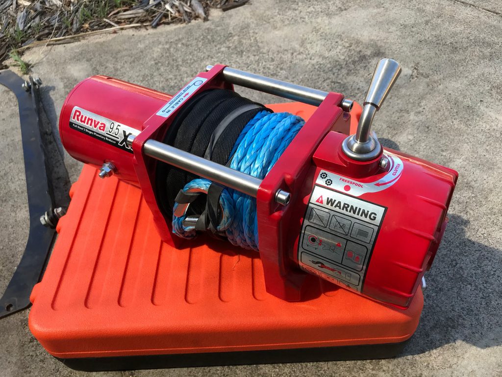
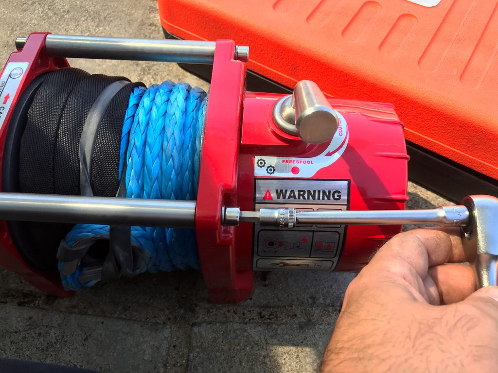
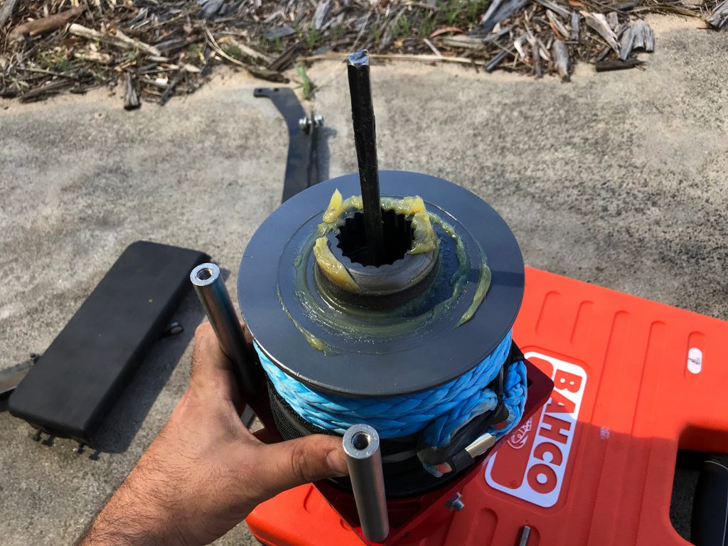
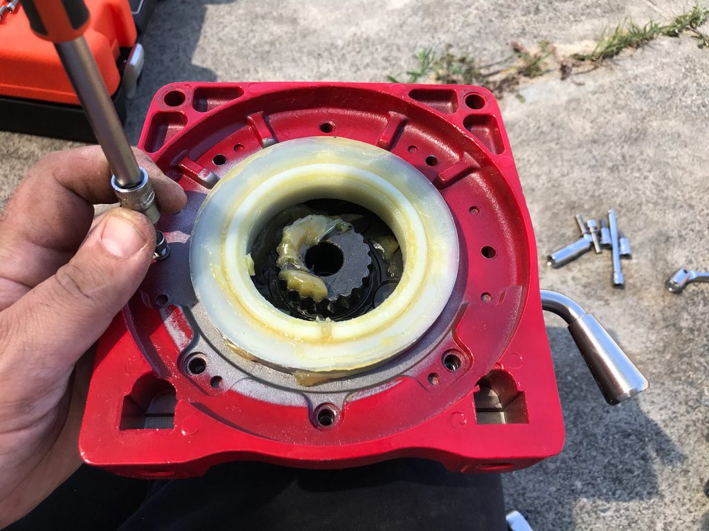
A huge benefit for this application is they can be mounted either feet down or forwards (not all winches can) and there’s a relatively simple way to rotate the gearbox assembly to correctly position the freewheel lever. Some winch manufacturers want you to get them to do the rotation to not void the warranty which is a bit sucky.
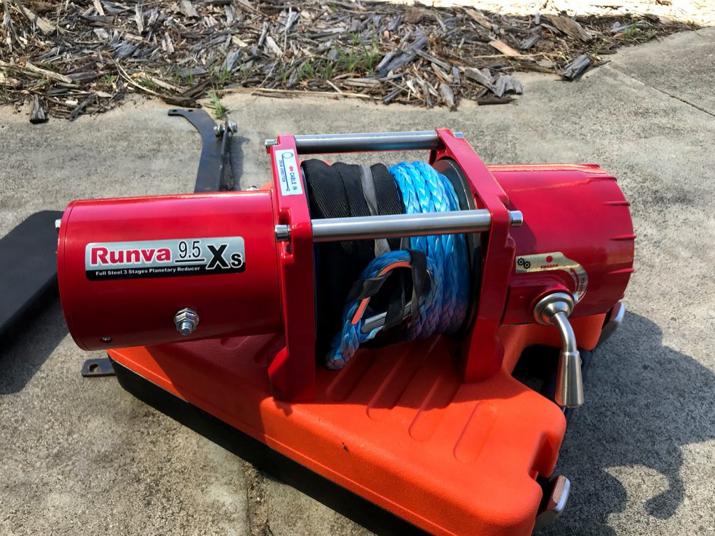
The one downside to this winch is specific to this use on the ARB bar: the ARB features a full-footprint winch size, but the winch itself uses is it uses a slightly non-standard narrow footprint of 5.9 x 4.5″ for the bolts: more typical seems to be 6.0 x 4.5″ or even just 4.5 x 4.5″ bolt patterns for the ATV winches. This means there’s no commercial adapter plate to bolt it up to a ‘standard’ full footprint and the preexisting cutouts of the ARB bar.
Other options that seem popular is to go the Carbon winches, either in 6000 lb guise (same weight as the Runva 9.5XS) or 4500 lb (~12 kg!). I can’t speak for their reliability or similar but it’s worth exploring options here.
Winch specs and considerations
Something to consider with a winch is its performance in terms of power comes down a lot to leverage. The more winch rope you have on the drum the less leverage it has and thus the less pulling it can do. By doing some maths at the maximum it can pull at various amounts of rope left on the winch, these are the specs for this winch. I have translated these into kg from the lb specified by Runva
| Drum layer (#) | 4 | 3 | 2 | 1 | |
| Amount of rope out of drum (m) | 0 – 2 | 2 – 7.5 | 7.5 – 12 | 12 – 15 | |
| Load compared to max (%) | Current draw (A) | ||||
| 0% | 80 | 0 | 0 | 0 | 0 |
| 32% | 170 | 803 | 930 | 1106 | 1364 |
| 63% | 260 | 1606 | 1861 | 2212 | 2727 |
| 100% | 380 | 2542 | 2946 | 3503 | 4318 |
You can see just how easily you can exceed a winch’s rating f you don’t have most of the rope out, even with a light car. Not that this should stop people buying smaller winches, but helpful to understand how the amount of rope and then the load compared to what the winch can theoretically do relates to the current that the winch will draw.
Installation into an ARB bar
A key element to the ARB bar is that it is winch compatible; however, there are a couple of caveats:
- The bar requires a small/mid frame winch (i.e. full sized winches might not fit)
- The bar also has a standard winch footprint (10″ x 4.5″ bolt spacing – 254.0 x 114.3 mm)
- You will need to sort out a winch control unit mounting system; the ARB installation kit is just a bracket specific for the control box for the winch they sell for the bar.
ARB designed the aperture to fit the mid-frame Warn M8000 winch but at 32 kg I’m less keen on running it. Additionally it is much more expensive than the Runva winch and still runs steel cable; respooling it with synthetic rope adds to the expense.
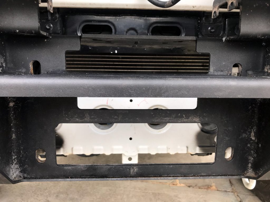
Getting access to the winch aperture
Although it is easier (and with heavier winches advisable!) to do this with the bar off the car, you can do the installation with the bullbar still on the car. This is good for me as I wanted to use the car while I work around doing the installation.
You start by removing the splash guard at the bottom of the bullbar. This comes off with just a few 10mm headed bolts. Below this is is a stiffening plate which goes onto the crash structure of the car, and you need to remove this too. This stiffening plate has some 17mm headed bolts with 15mm nuts at the back in the crash structure. These nuts are plain nuts and I found I could hold them with a spanner carefully and then spin them off. It’s actually a bit sucky that ARB haven’t done something like installed rivnuts in here but anyway, it is what it is.
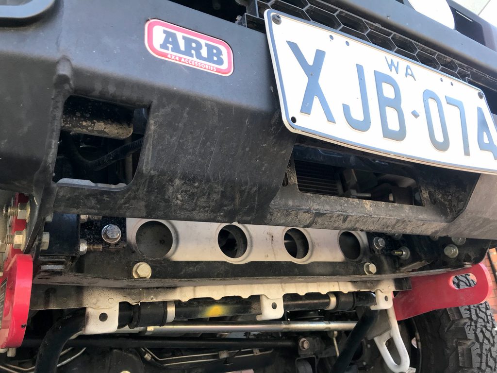
Note that with the mounting plate removed from the crash structure you have a fair bit of room to push a winch up from underneath. Nevertheless, really big winches might need the bar removed as there is more space once you’re up and in there with the winch.
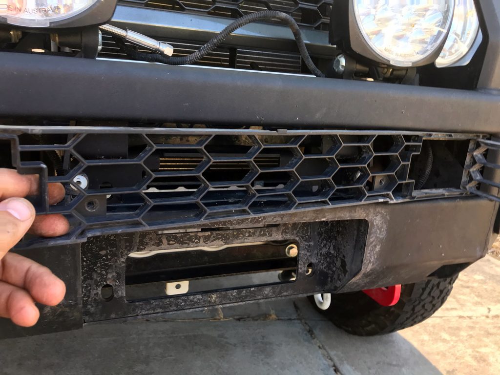
To get access to the front part of the winch aperture, start by removing your numberplate from the mount. You can now get access to the 3 x 10mm headed bolts that hold the plate mount on. There are 10mm nuts up in the plastic trim area that you hold with a spanner to start undoing them.
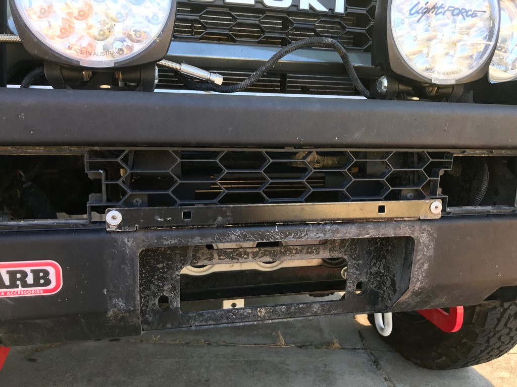
With the plate mount removed the next step is removing the plastic trim. There are two screws to remove here as shown in the previous picture just above the numberplate mount.
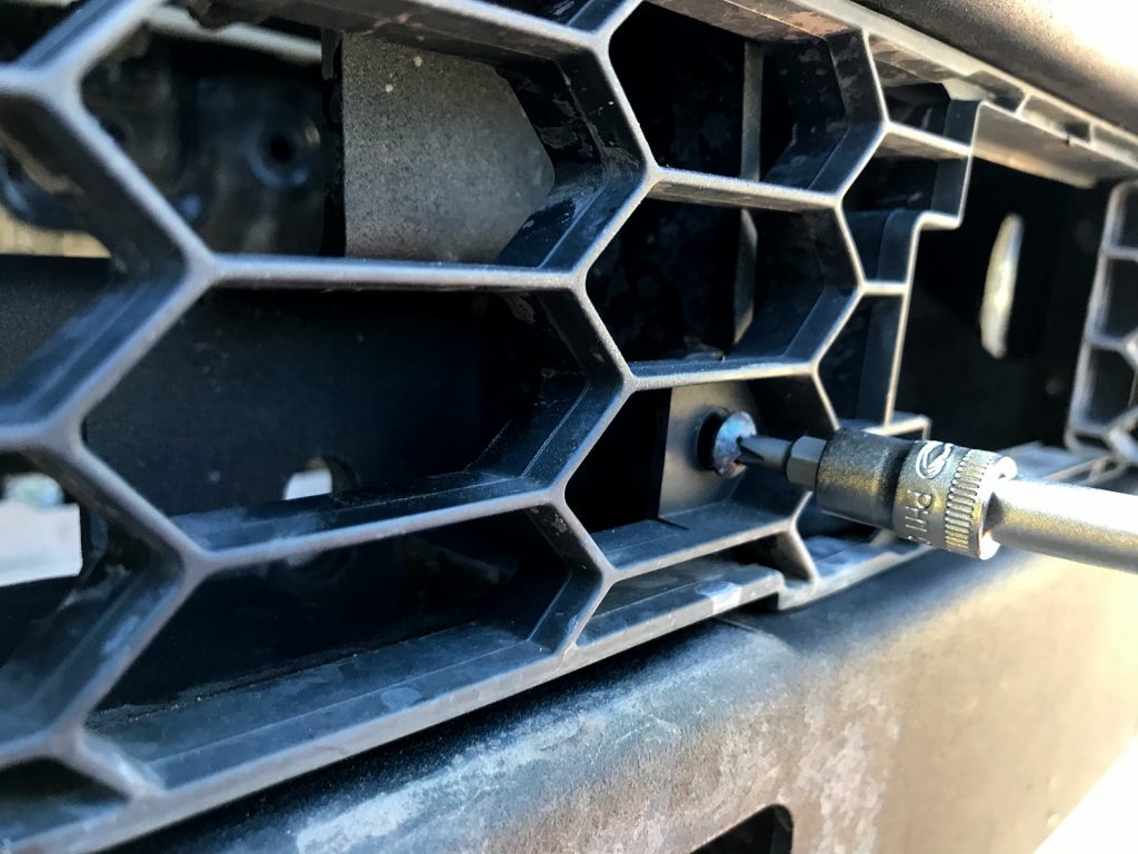
Once those screws are removed you bend the ARB grille out a bit in the middle which pops one of the ends out, and then just slide sideways to remove the other end.
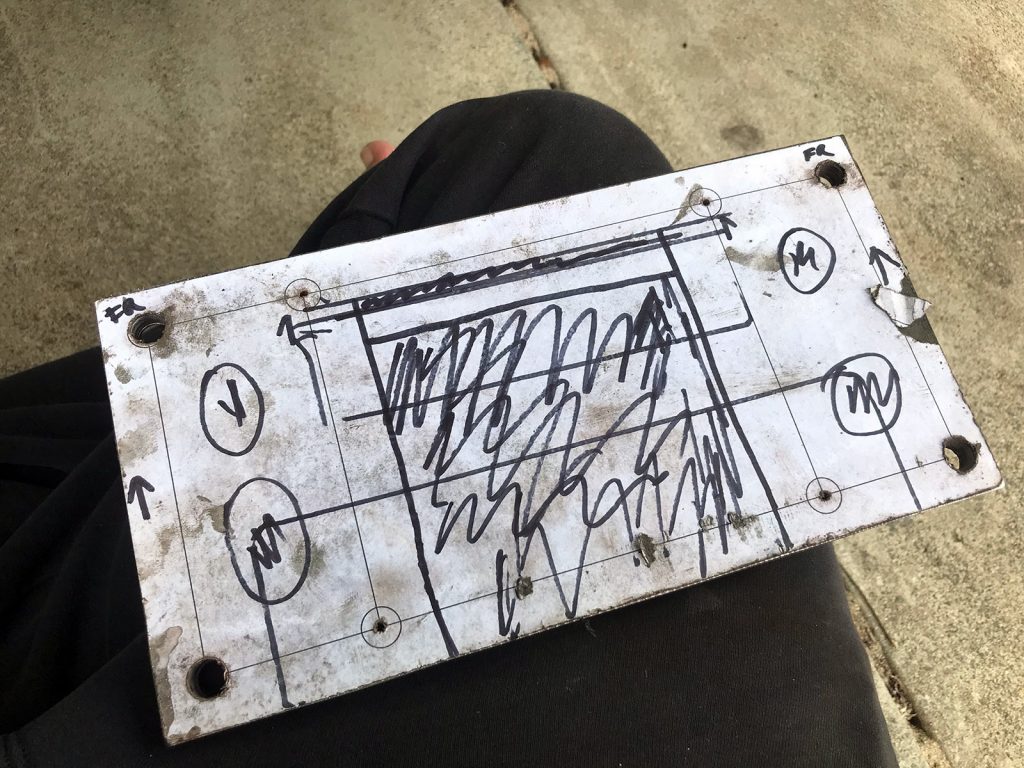
Designing up winch plate
As stated above, the downside to this winch is the smaller footprint of it. Fortunately it’s quite easy to make up a winch plate and you don’t need fancy CAD software to design it up… just use powerpoint or something you can draw in. You need to be able to draw something about 270mm wide and a bit over 160 mm tall so landscape orientation A4 paper with zero margins is perfect.
Now create two rectangles on this blank drawing: one is to be 10 x 4.5″ or 254 x 114.3 mm high and wide; the other 5.9 x 4.5″ (149.9 x 114.3 mm). The corner of these rectangles represent the bolt centres for each of the holes. You can select the two rectangles and align them around their centres and everything will line up ok.
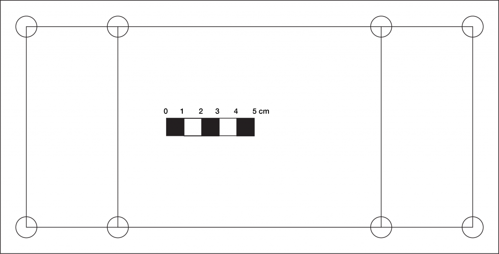
There’s also a need to cut out some material in the middle for where the rope will actually exit the winch. Measure this on your own winch and position it according to where the bolts are.
You can also design in some extra cutouts to remove more material to make the adapter plate lighter. I actually didn’t do this and didn’t consider where to mount my fairlead so I had to make up little plates to make up the difference which you’ll see as I cut it out.
Print it out and then stick it to the chosen bit of steel to make up the plate. You’ll now have easy to lay out marks to drill and cut various parts to make the plate up.
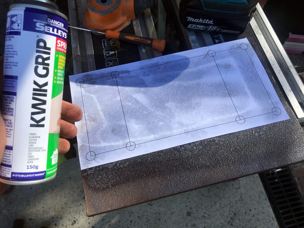
Regarding the steel it doesn’t need to be extraordinarily thick, it will be stiffened by being bolted to the bullbar. You don’t need anything fancy here and you don’t really need the thickest steel, just enough to be able to carry the weight of the winch as it bounces around. Consider that the ARB bar is mostly 4mm thick steel and if it was a full frame winch that’s all it would be bolted to… unfortunately in my pile of scrap metal I only had a 9.5 mm (3/8″) steel plate so that’s what I used. It did mean I had to remove as much material as possible to not make the winch excessively heavy… I ended up with a plate that weighs a bit under 2 kg which is ok: without any cutouts it would be nearly 3.6 kg though!
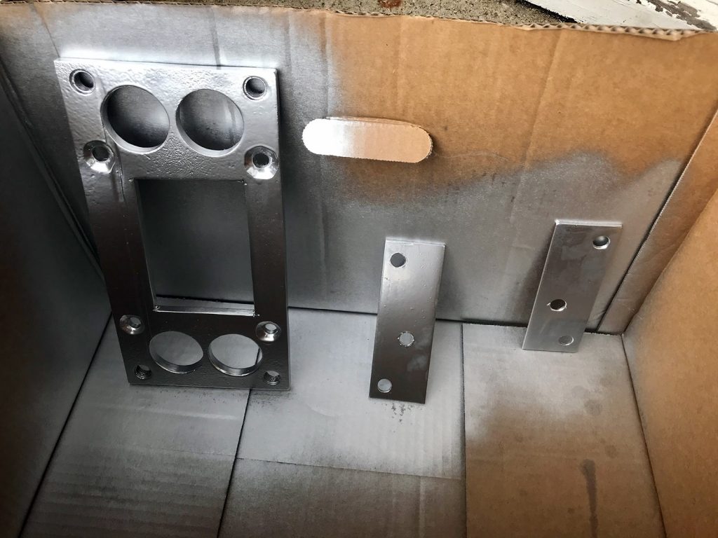
Fabricating winch plate
With the plate prepared I started drilling out the mounting holes. These went out to 10.5 mm in diameter to accommodate M10 fasteners to suit the winch.
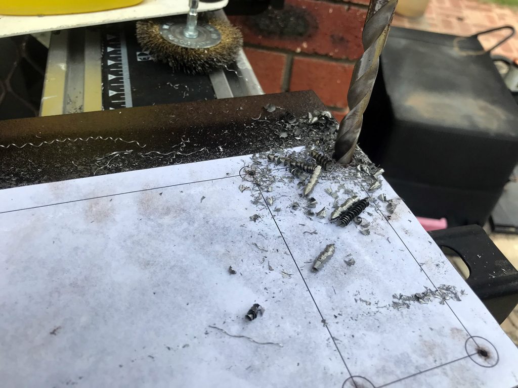
You then need to start thinking about how to accommodate the cutouts to suit both the bar and the winch for the rope to go through.
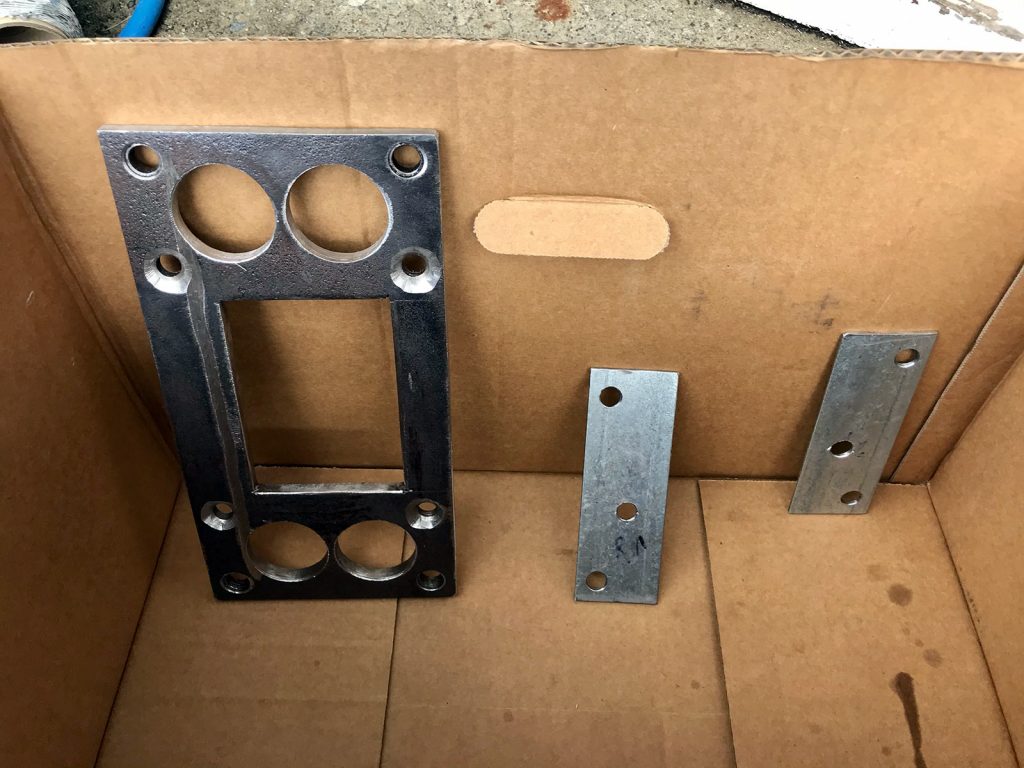
I did some quick eyeballing and freehanded the cuts with an angle grinder, using a drill bit to get the corners niceish and then cleaned them up with a file. I did these cutouts without finalising the winch mounting holes due to needing to source some less-crap drillbits. Came up ok, and I added some holes on the side to remove a bit more material to make the plate a little lighter.
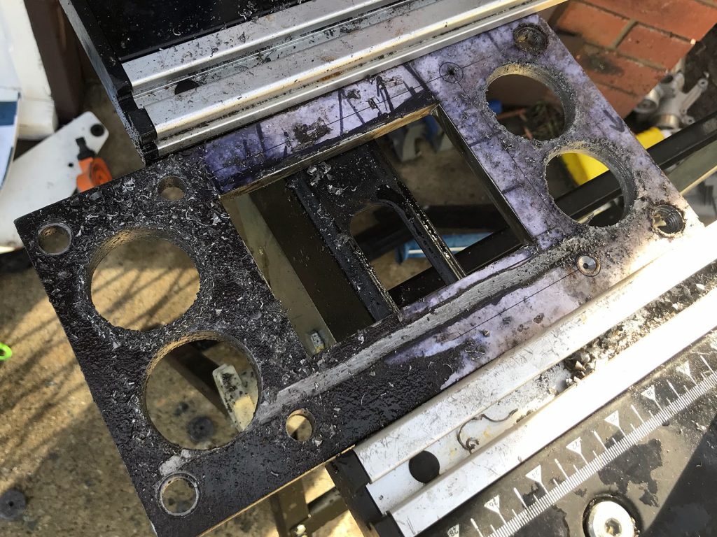
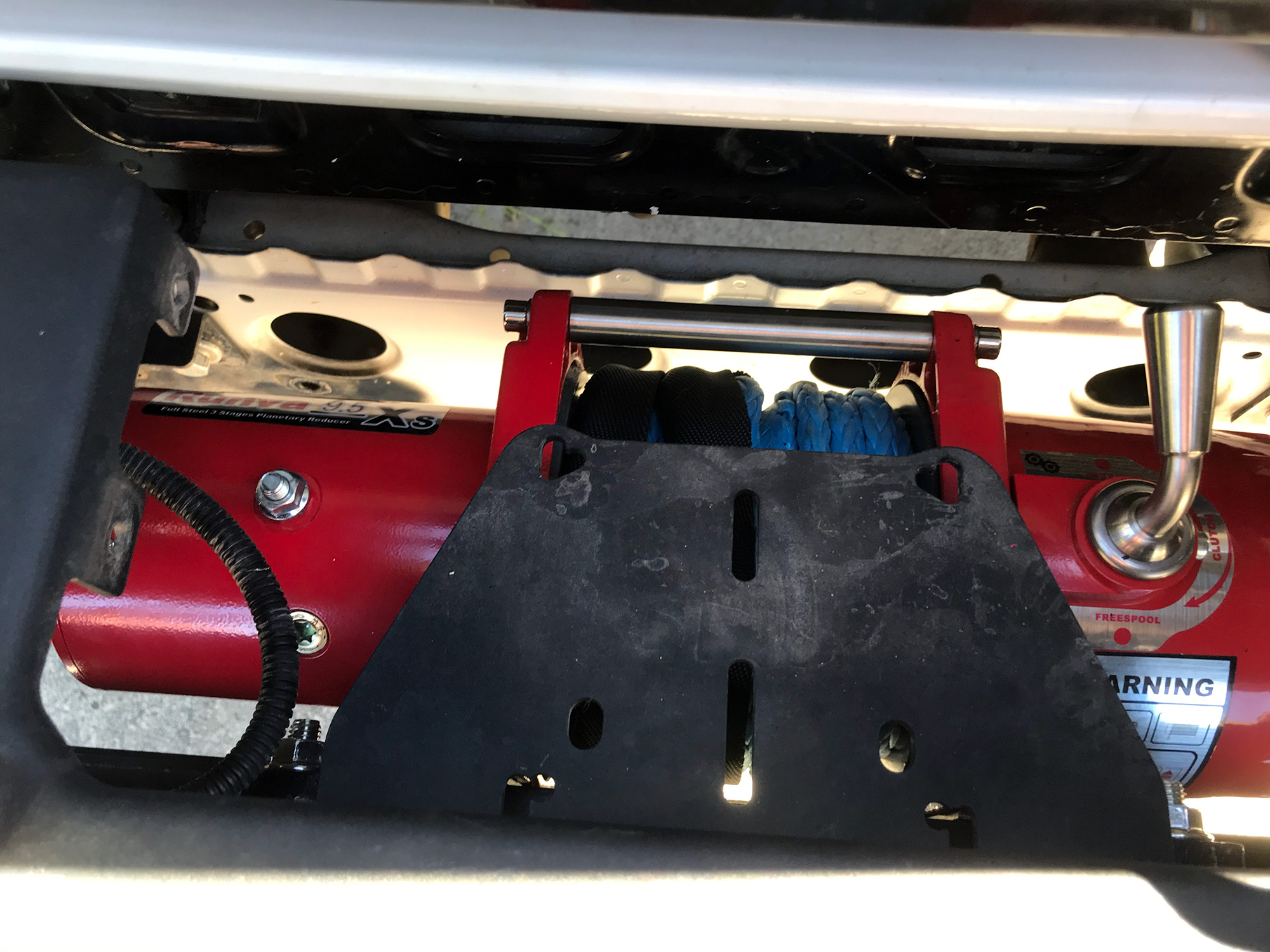
Chucking the plate on indicated that everything looked pretty good…
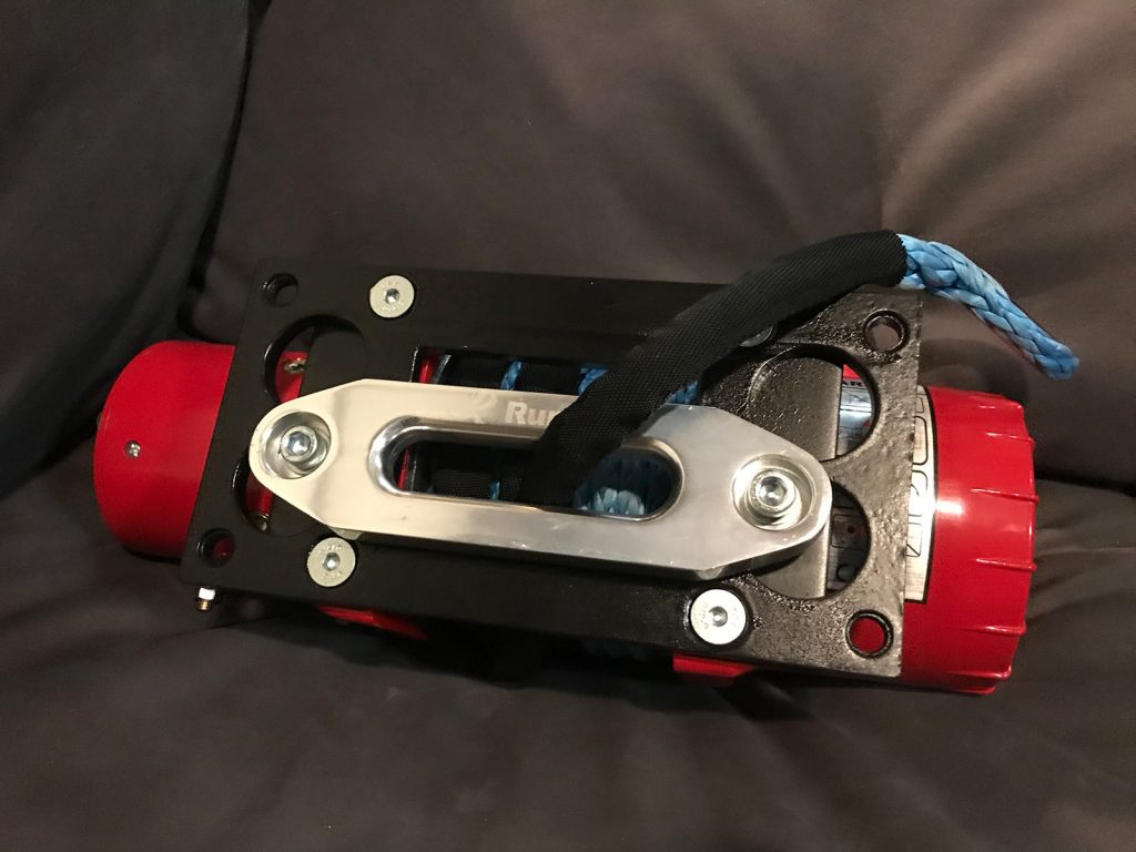
… except my awesome holes to make the plate lighter meant I couldn’t easily attach the fairlead. The ground-away line at the top of the winch area is to accommodate a rib in the ARB bar.
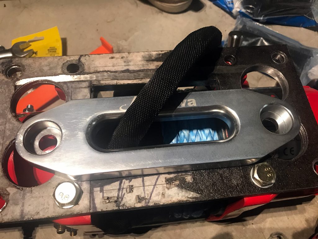
The problem is you can’t have the fairlead right at the bottom because it will rub on the plate as it exists, and you want to keep the stiffness to keep the frame stiff against the bullbar. It turns out it was a blessing to need to mount the fairlead some other way as I could use thin steel, some spacers, and this gives me adjustability in height positioning of the fairlead independently of the plate.
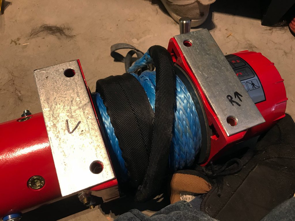
The two holes keep the fairlead mounting plates from moving with respect to the winch plate, and then it’s a case of just having some extra holes at the right height/spacing for the fairlead and all will be good.
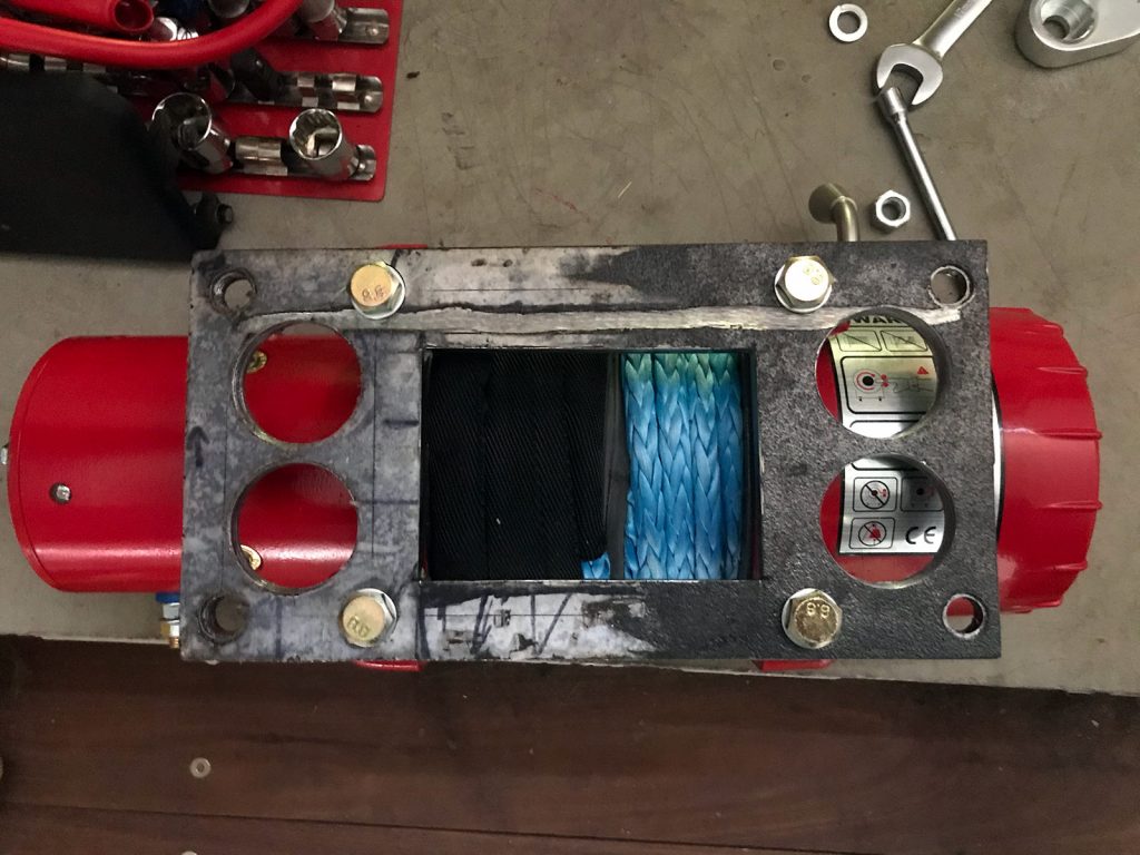
At this point it’s a case of selecting the right height and testing the layout. Note the use of nice countersunk fasteners: these are needed as the plate will be hard up against the bar, and you need to be able to have it all together on the winch as you offer it up to the bullbar.
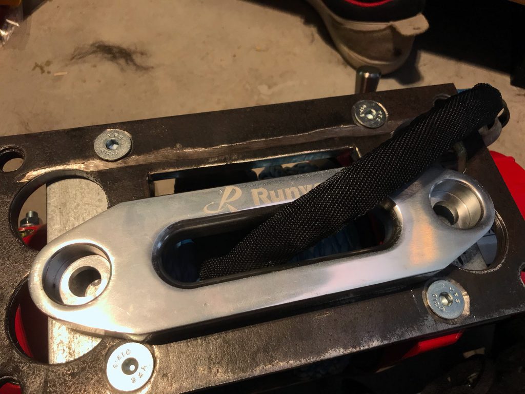
Once the geometry is all finalised then it’s off to the paint booth for an undercoat and then some top coat. I only got a pic after the first coat of black paint but you want to get good coverage here to make sure it’ll remain rust free.
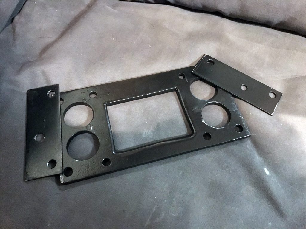
At that point you can do final assembly and lay everything out on the winch to see how it looks.
Fitting a hinged plate mount
Another part of prep you’ll need to do is to think about what you’ll do with your numberplate. Some people mount it up a bit higher to accommodate the winch rope coming out, but I prefer flip mounts.
To make reinstallation easier and also to make mounting the flip plate easier, I chose to install rivnuts in the ARB plate mounting bracket so it was easier to bolt to the bullbar and also for the flip mount itself.
Wiring and related control
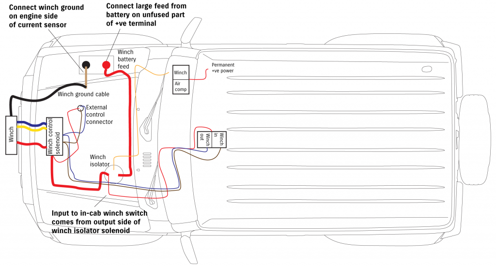
I’ll start off with my overview of the wiring plan which will help explain what I’m after here.
A few things about this before we get into the how and some more pictures.
I wanted in cabin winch control, and I don’t rate the Runva wireless controller. It works out but it is not waterproof and stripping it out of the main controller housing means it all fits underneath the bullbar winch plate. The solenoid itself is waterproof though so it’s fine down there.
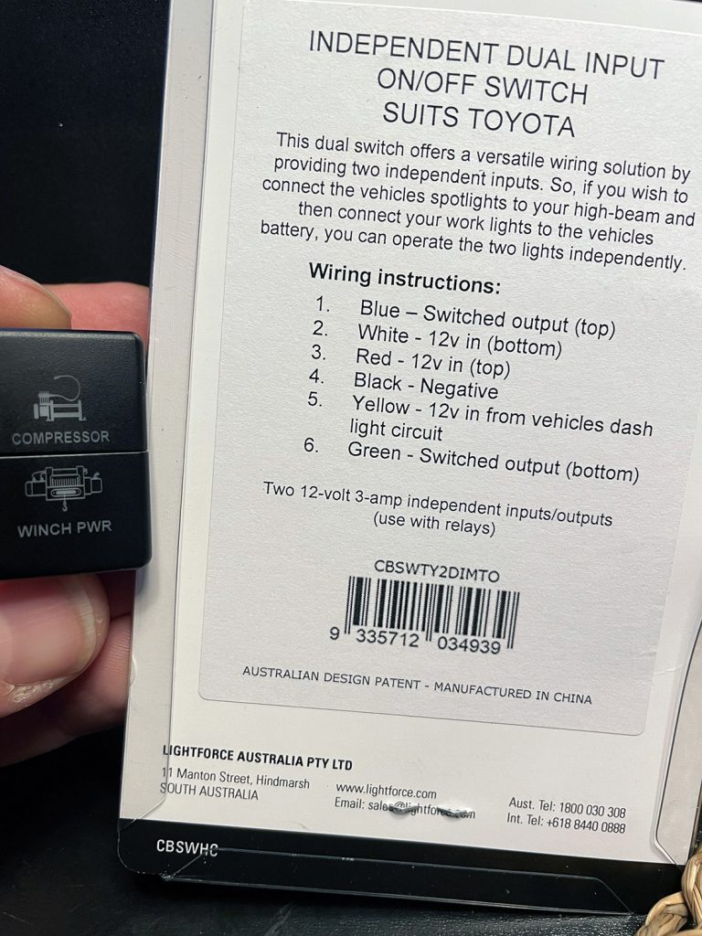
To isolate the winch when I don’t want to use it I used a 500A isolator relay. Pre covid these were cheap, now they aren’t. I opted for a Stinger 500A relay. You trigger this with 12V on the low power side, which I supply via a custom two part switch from Lightforce, with the other part of the switch powering the onboard compressor relay.
I used a generic two-way toggle switch for the winch direction controller. Not hard to wire it up, you just need to supply 12V either side of the winch solenoid.
I made up much thicker power cables for the winch than were supplied, and some of these cable lugs were made up with 90 degree lugs to make wire access easier. This isn’t essential but it minimises voltage drop which helps out weedy electrical systems like the Jimny has.
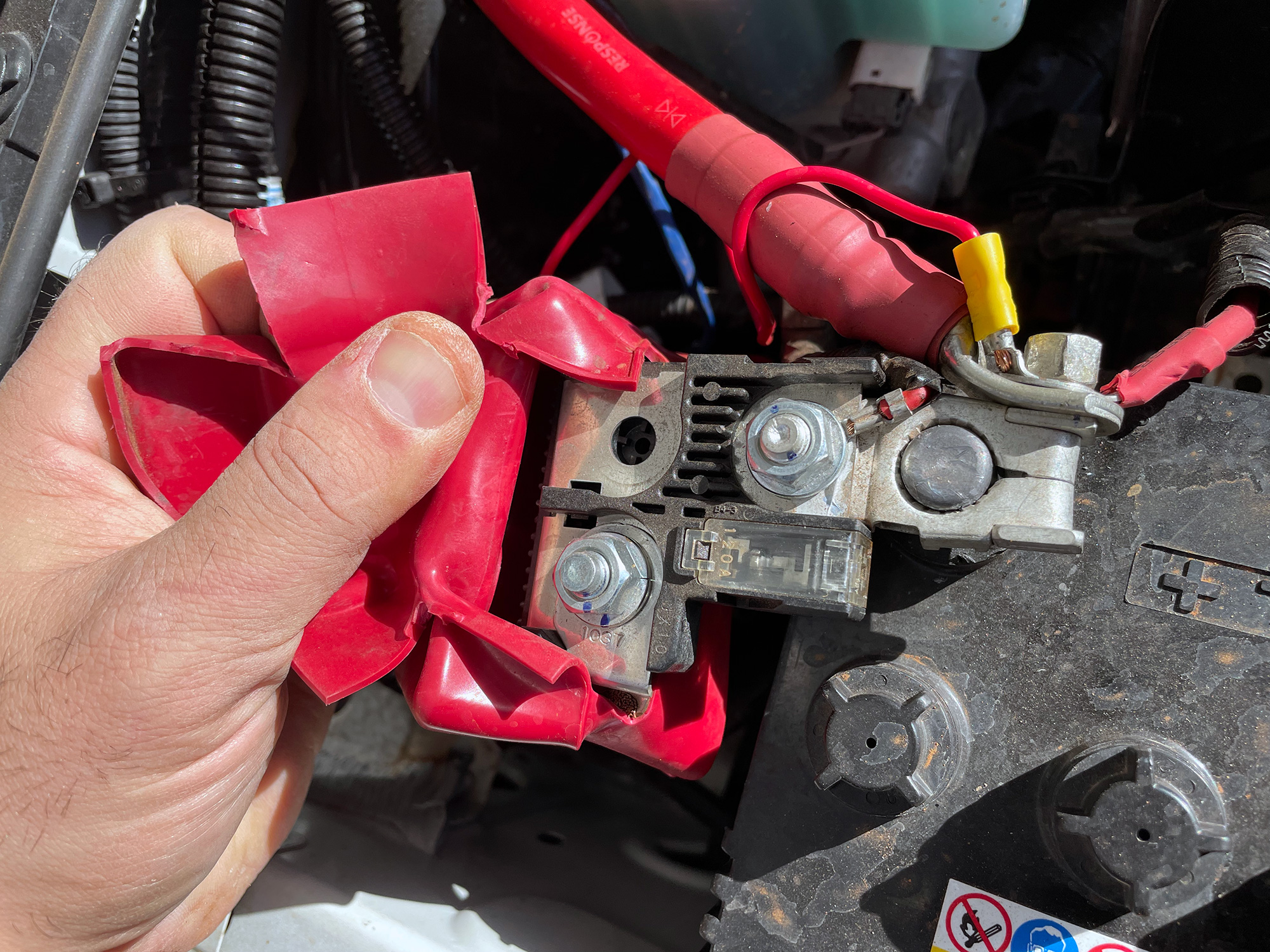
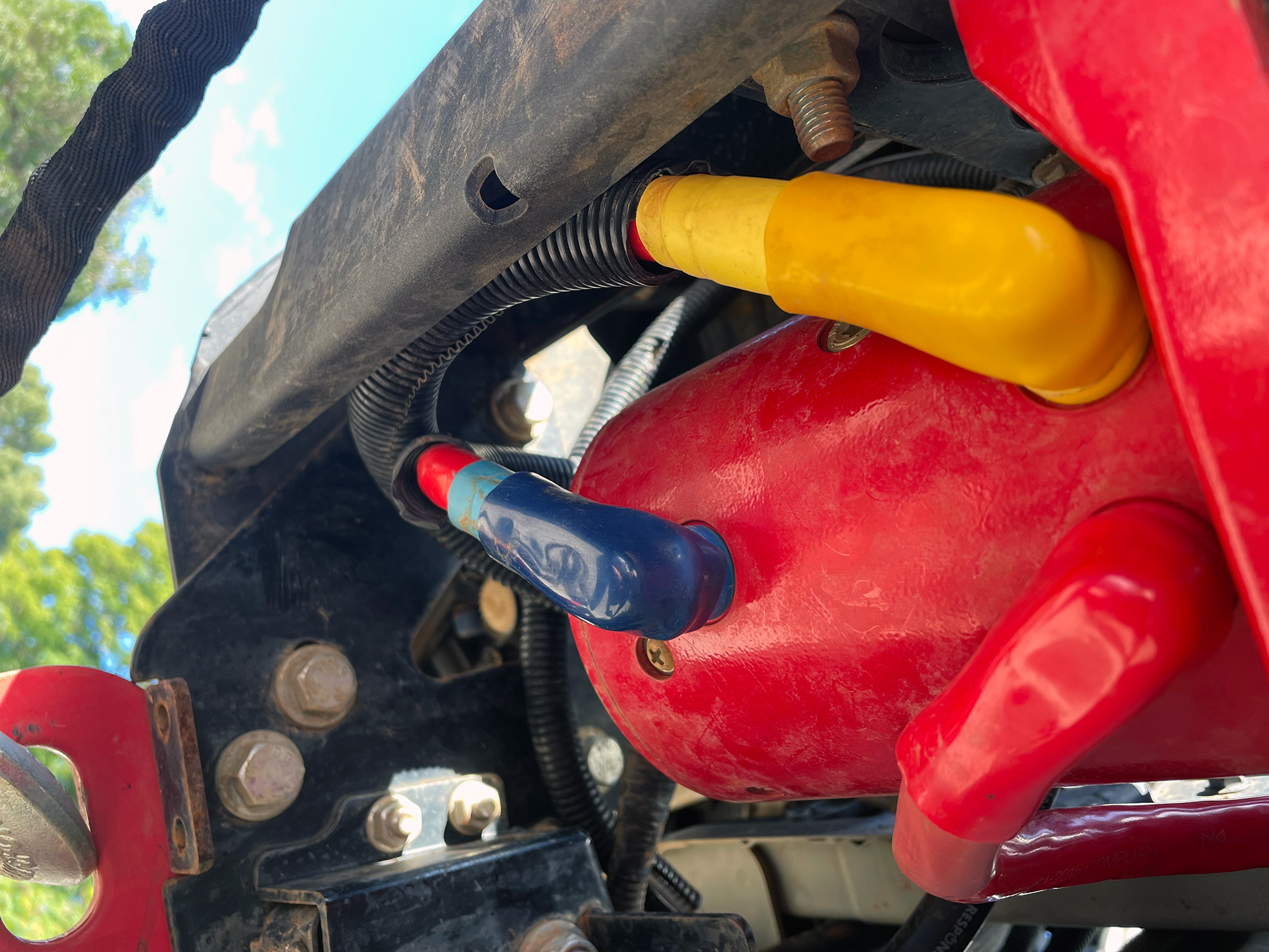
To correctly power the winch, you need to source power from an unfused side of the positive battery terminal. If you hook it up on the fused side then when you do a big pull with the winch it will blow the car’s main fuse. Instead, hook the fat power cable like here: to the bolt directly onto the clamp.
You also want to make sure it is earthed on the negative terminal through a way where the current draw sensor can detect it. I illustrate that requirement here on how to external the earth through the current draw sensor for the smart alternator.
Mounting control unit, power isolator and external controller port
There’s multiple options here. Usually people keep the winch control unit within the factory case with the wired control connection, however this is bulky and harder to accommodate nicely with how I want the winch. By dismantling the winch solenoid box you can extract the relevant control solenoid and discard the giant box it sits in.
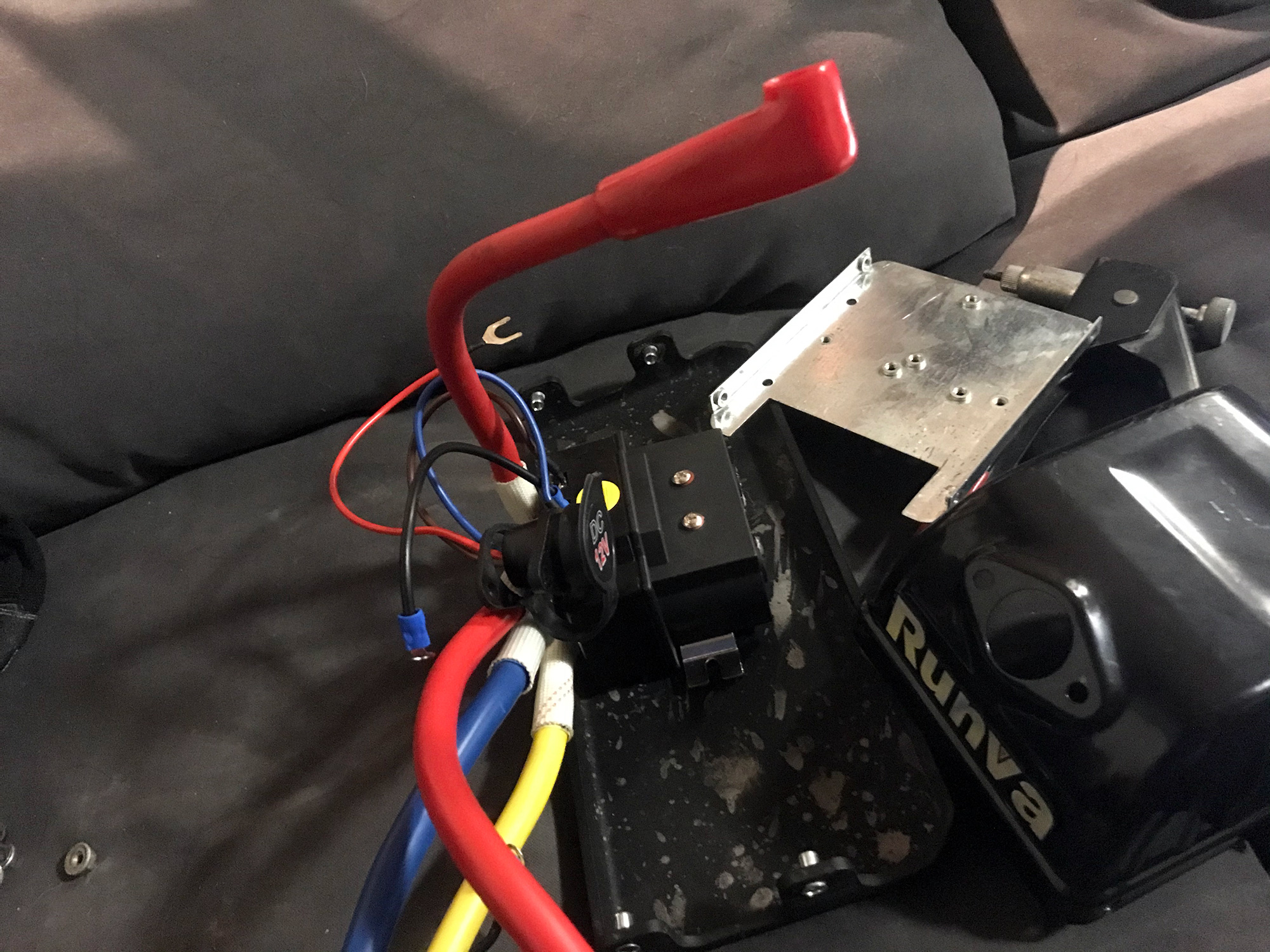
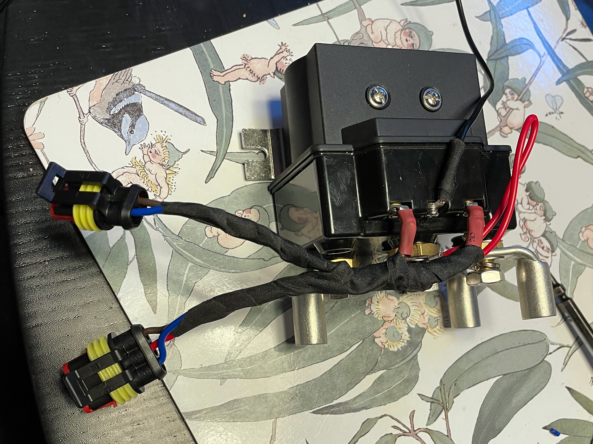
The solenoid itself is waterproof and quite small, so I chose to mount it on the plate above the winch itself, with the removable panel in the bullbar modified to accommodate the external winch control lead.
I originally mounted the control solenoid to the upper part of the bullbar on the removable panel but it made accessing the top of the winch too annoying.
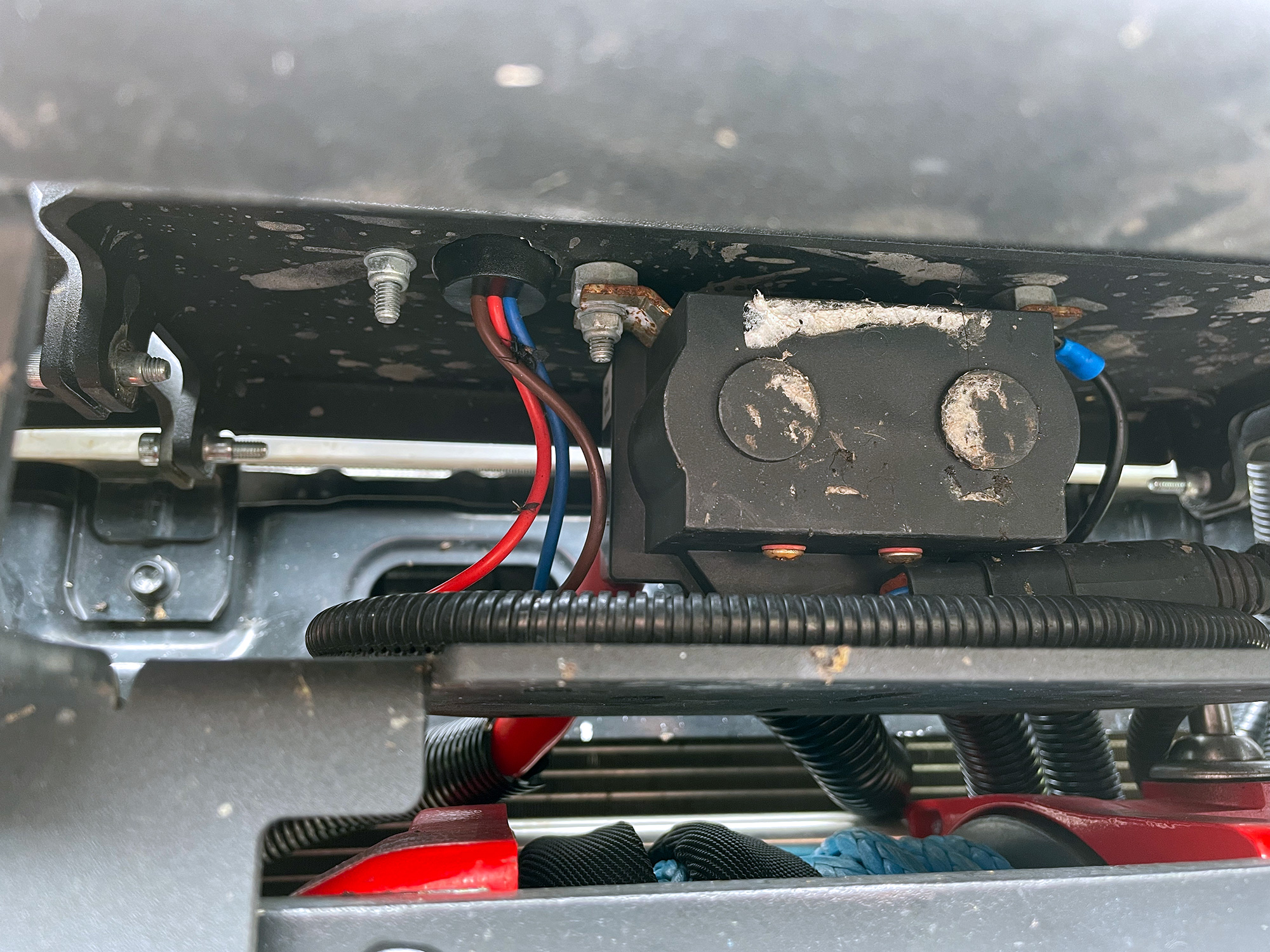
I have now mounted it on the mounting plate above the winch. None of the holes line up with the mounting bracket on the control solenoid but easily fixed with some rivnuts to bolt it down.
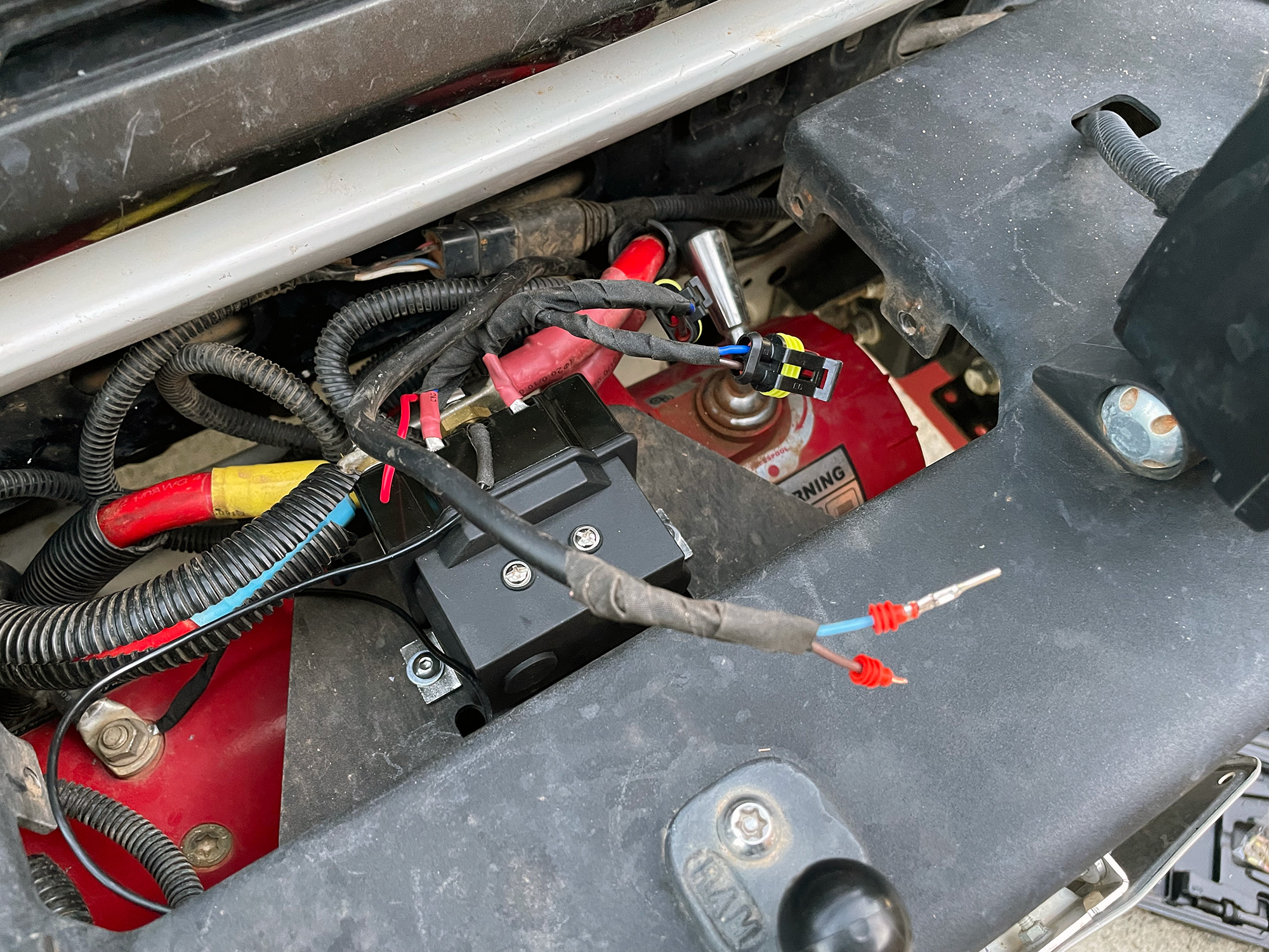
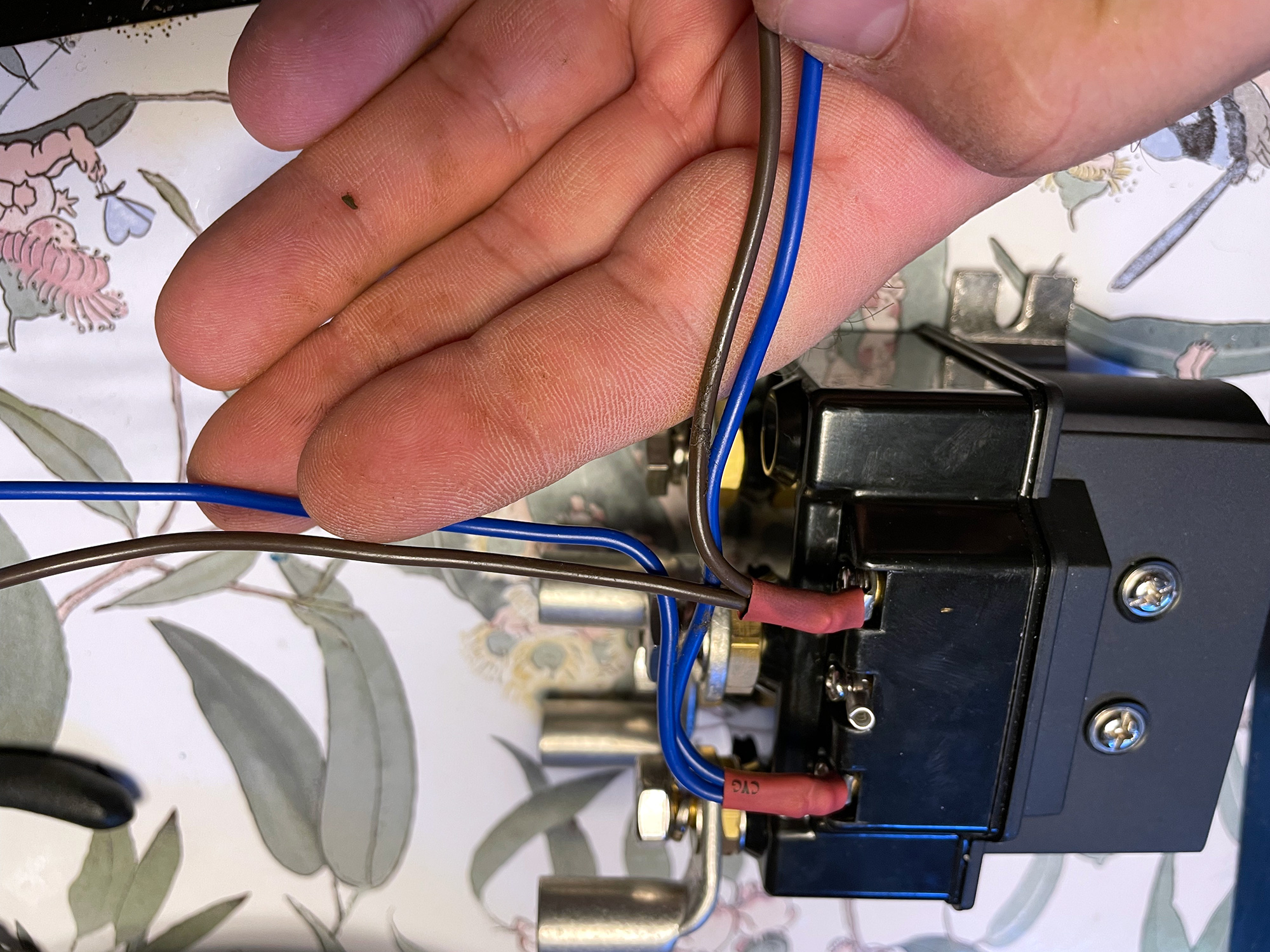
Here’s prepping those wires before putting the solenoid in the car. Applying 12v to the blue wire makes the winch go one direction; it goes the other way with 12v applied to the brown wire. The middle of the small terminal is fixed to ground.
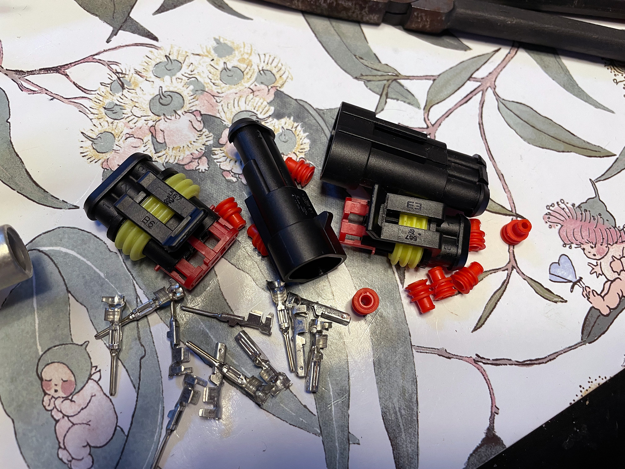
External controller port is easily mounted too, just a big hole and 2 smaller ones and bolt it in. I made up this to be on a waterproof connector to the solenoid to make it a little easier to take the upper plate off. Note the external controller connector needs 3 wires: power in, and then 2 leads back to the solenoid. Grab the power in from the control solenoid input power lead, which ensures it only has power when the winch is energised through the isolator. I used AMP Superseal connectors to make the cover plate and also the bullbar itself removable: the 3-way connector is just able to fit through the hole needed for the external wired controller connection so it all is easily fitted. A 2 way fitting goes back to the engine bay for connecting to my in-cab controls.
You need the control unit and isolator mounted to work out cable lengths so making up custom power cables for the winch is next!
Making up power cables
Making up cables is pretty easy but you will need heavy duty crimpers. They don’t have to be fancy hydraulic ones to get this done though it is a lot easier to use them than long handles. I use high leverage plier style crimpers but hydraulic ones are coming down in price.
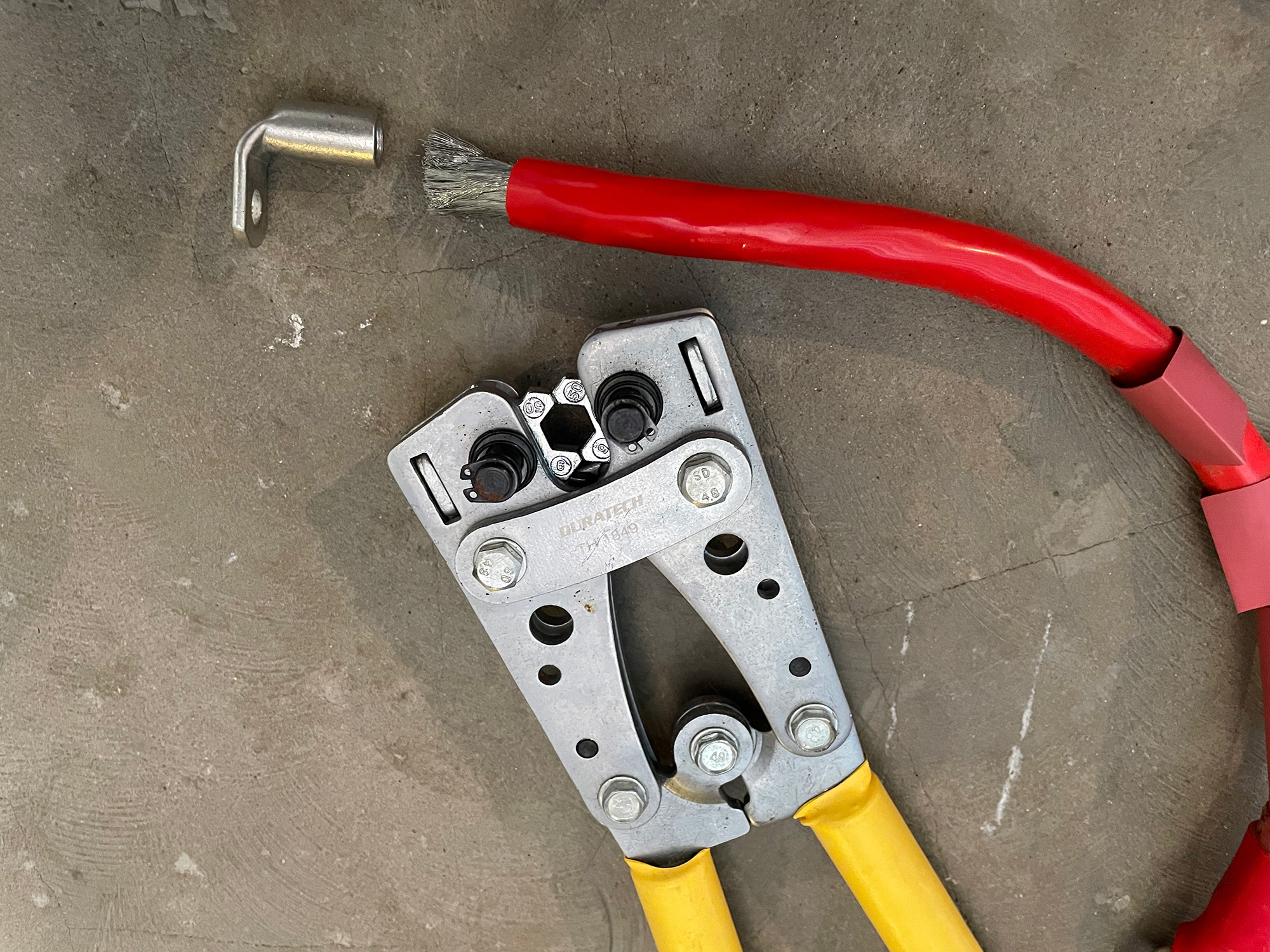
I used 50mm2 cable which is probably overkill for the cable runs but it wasn’t much more expensive than smaller cable. I couldn’t source appropriate colours for the winch cables from the solenoid so I elected to use heatshrink to keep track of cables.
It’s always painful to get the terminals on thick multistrand cables but you’ll get there.
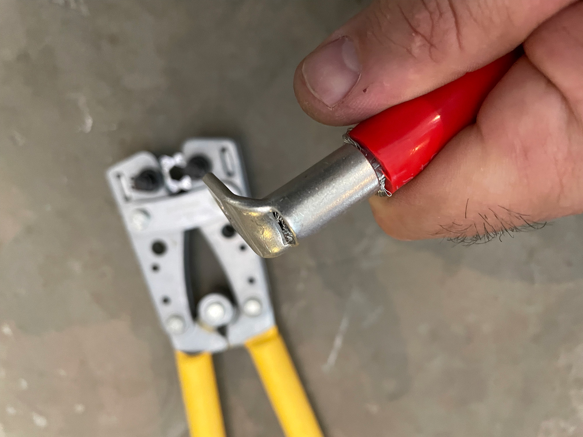
Then just give it a squeeze in a couple of spots and you’re sorted.
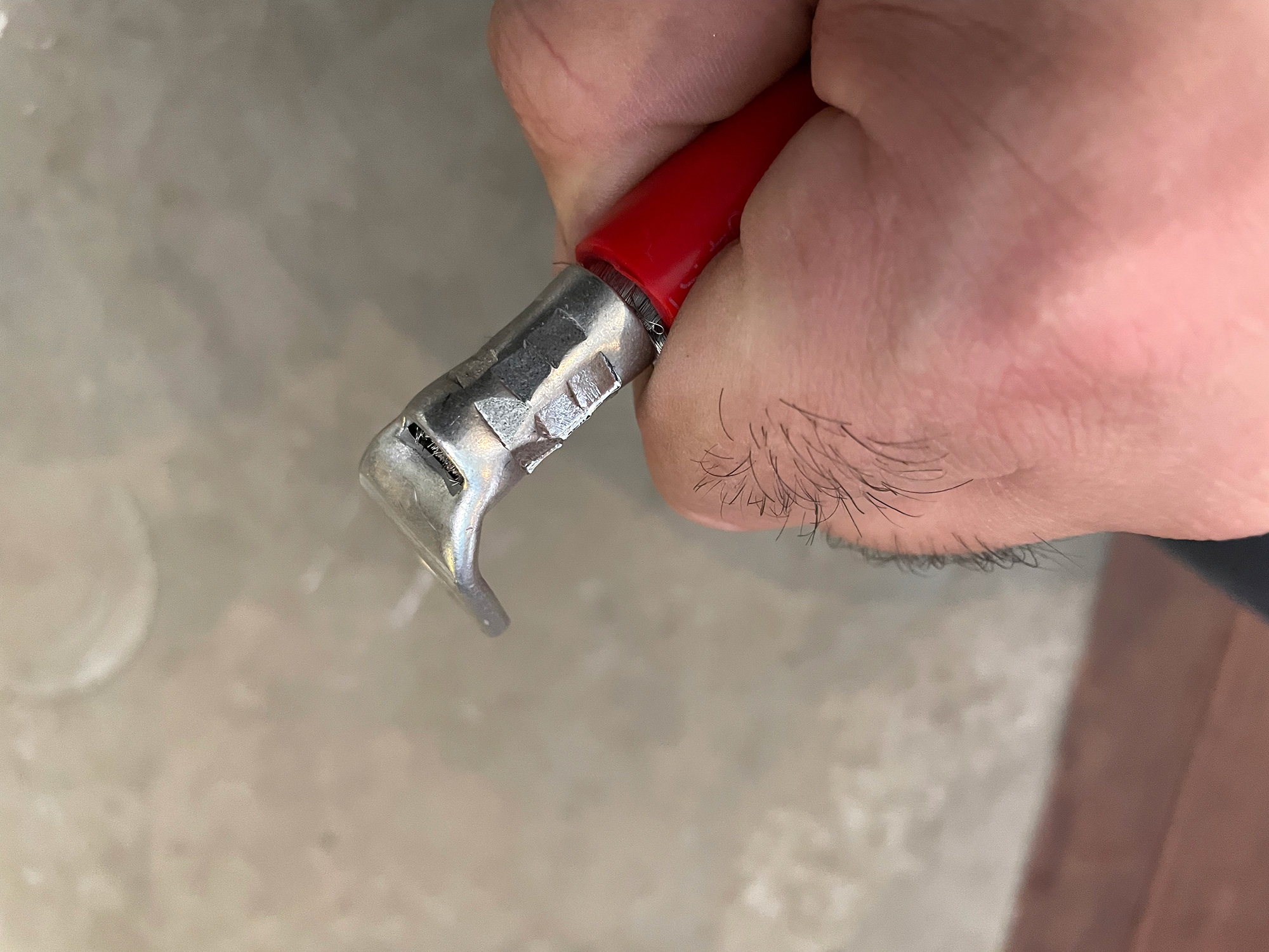
With a good crimp using a correctly sized terminal you will find no need to add solder or anything. Solder tends to make a spot ready to fatigue in the wire so I prefer avoiding it.
I use heatshrink to both support the end of the cable and also to keep things insulated. With big terminals I usually use two pieces to ensure good coverage over the terminal and also good support for the wire into the terminal.
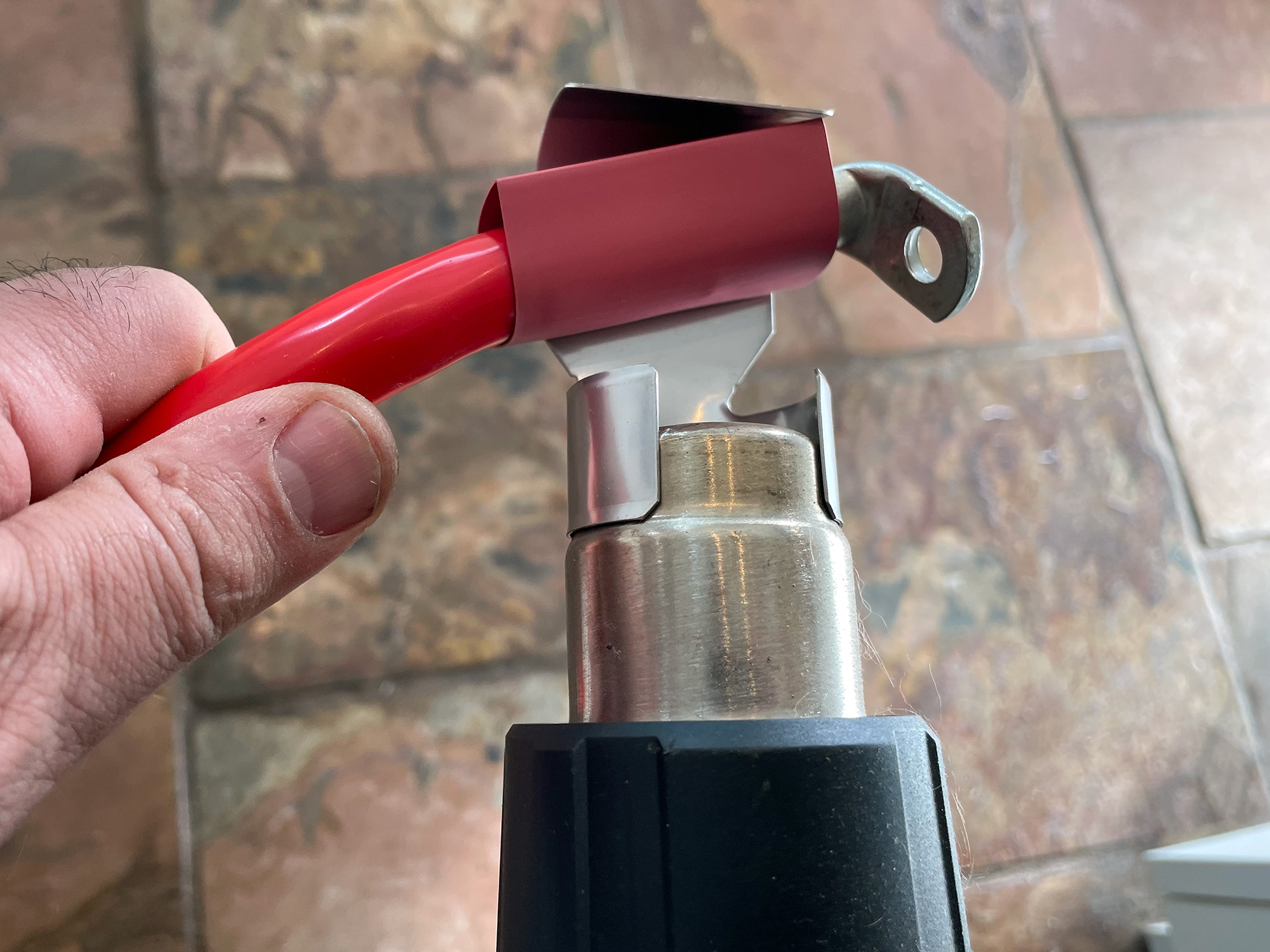
Not that you can tell easily but here it is with all heatshrink done.

It’s also important to put on a terminal boot to ensure things can’t short out. You can pick this up at various electronics components retailers; sometimes places that specialise in winch components will have them for sale, too.
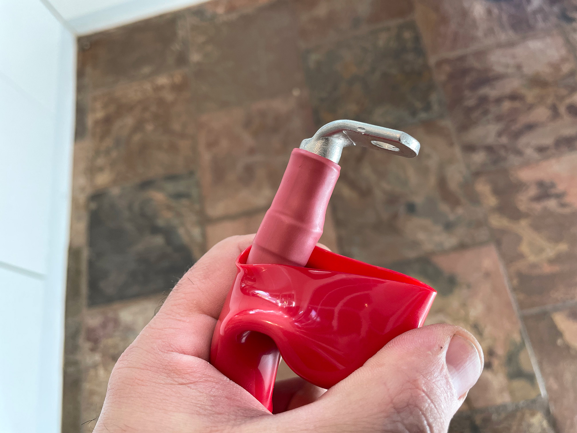
For the winch end and the colourful boots I usually reuse manufacturer’s boots off the piddly wires they provide as these are harder to source. You will also see in this shot I protect the wires with plastic split loom covers too. This is because it’s really common for vibrations to rub wires around near winches, and when the insulation is covered with dirt it becomes like sandpaper. Adding an extra layer of protection makes a big difference to wire longevity.
Switches
Nothing fancy here. Short Toyota switch in the dash for the winch isolator and then slight enlarging of the switch cutouts in the centre console for the Carlin/ARB style dual action momentary switch for the in-out control.
I have the winch with permanent power as it gives me more options should the engine not be running cause I’ve drowned the motor or something.
For future upgrade potential I actually ran multi-core cable from the engine bay to the centre console. Because of the arrangement of how I have the underbonnet compressor this future proofs me if I want air lockers, but it does mean I need to join the multi core loom from the centre console to by the compressor to another cable run of multicore cable down to the winch solenoid. Easy done with some waterproof connectors.