
2019 Jimny audio upgrades
I’m still waiting on some parts, but here’s some documentation on doing audio upgrades on the JB74 Jimny – and applies to the JB64, too. Where I know them I’ll add part numbers but also make sure to check with dealerships as a lot of this is off sketchy printouts people have got in some of the Jimny groups on FB or forums.
Jump to section:
- Parts I used
- Head unit
- Installing new speakers
- Factory optional stuff part numbers
- 5 door Jimny XL info repository
Parts list
- Front speaker mounts: Suzuki 5.25″ plastic speaker brackets/spacers, part number 99197-78R00
- Rear speaker mounts: Suzuki 5.25″ metal speaker brackets, part number 99197-78R00 (possibly R10 for some markets)
- Front and rear speakers: Rockford Fosgate R1525X2. Factory speakers are Pioneer 5.25″ 2-way speakers, part number 99000-79BJ0-R00, which I believe are Pioneer TS-G1320F speakers. The Pioneers have the correct holes for the factory brackets but not too hard to modify to suit – see my install instructions.
- Underseat subwoofer: Kicker 11HS8
- Connectors to make up the speaker connectors to the wiring harness: Narva 56272BL.
A couple of notes on the parts list
- I went for the Rockford Fostgate speakers mostly cause I like them more than I like the Pioneers that Suzuki supply and that are a direct fit for the brackets. Some mods are needed to make them fit into the brackets). Potentially larger and/or fully split speakers would be better but I’m kinda into a stealth install and these will be good enough for me.
- Subwoofer wise there’s a few under-seat options but the Kicker gets good reviews
- Amplifier you could buy better, but I scored this unused 2nd hand and it will do for a car like this.
- I’d like a headunit upgrade sometime as there’s a couple of things that annoy me, but I also don’t really want one of the Android based headunits.
Head unit
Wiring details
Note: since I have a car with the Bosch 7″ infotainment system, I have gone off that. The head unit fitted to lower spec cars, and the temporarily used Australia 9″ Android based unit, probably have different wiring. I believe the car side wiring – which I am showing here – probably is the same so you might find this info useful.
5 door Jimny XLs use a Clarion sourced unit with a 24 pin connector for which I have very little info (and I don’t have a 5 door to do my own verification). At the bottom of the page is where I’ll collect info as I come across it, though note it will probably never be a focus of this site to expand too far into 5 door territory.
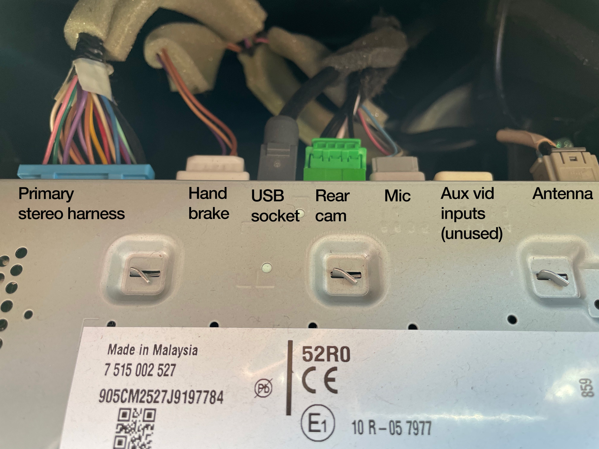
To illustrate what each connector does and its pin layout, the connectors are going to be labelled as they sit in the car, e.g. with the primary harness this has the clip part pointing down. This is upside-down to how Suzuki draw connectors, if you happen to compare it to a factory wiring diagram. I have used the numbering convention from the wiring diagram, so this is all consistent. I didn’t photograph the antenna connector as it’s not something people commonly ask for.
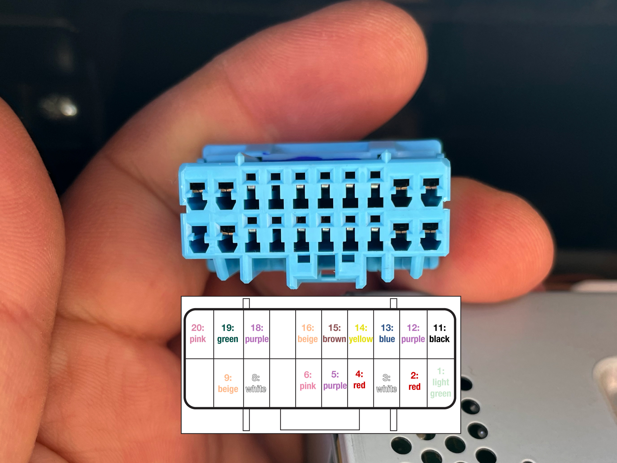
Main harness
Connector on radio is a Sumitomo TS series connector: 12×0.050″ pins, 8×0.090″ pins
| Pin number | Wire colour | Description |
|---|---|---|
| 1 | Light green | “RADIO” fuse: fuse 51, 15A, inside cabin; permanent power |
| 2 | Red | Illumination |
| 3 | White | Front left speaker +ve |
| 4 | Red | Front right speaker +ve |
| 5 | Purple | Rear left speaker +ve |
| 6 | Pink | Rear right speaker +ve |
| 7 | Unused and unknown | |
| 8 | White | Hands free switch of steering wheel controls |
| 9 | Beige | “ACC” fuse: fuse 66, 5A, accessory switched power |
| 10 | Unused – might be signal to antenna/amplifier remote turn-on | |
| 11 | Black | Ground |
| 12 | Purple | From gauges (presumably CAN) |
| 13 | Blue | Front left speaker -ve |
| 14 | Yellow | Front right speaker -ve |
| 15 | Brown | Rear left speaker -ve |
| 16 | Beige | Rear right speaker -ve |
| 17 | This appears to be used with the automatic emergency calling function for some parts of the world | |
| 18 | Purple | To BCM: vehicle speed sensor (Vss) output from BCM |
| 19 | Green | Audio switch of steering wheel controls |
| 20 | Pink | Audio switch of steering wheel controls (also links to hands-free control buttons – common for both functions?) Potentially ground for steering wheel controls based on other users’ feedback |
APP071 appears to be the Aerpro universal harness to adapt this main harness to the ISO harness arrangement.
Steering wheel harnesses are always a bit tricky as they multiplex signals, so it’s not a simple wiring arrangement for this; aerpro CHSZ6C appears to have you covered here.
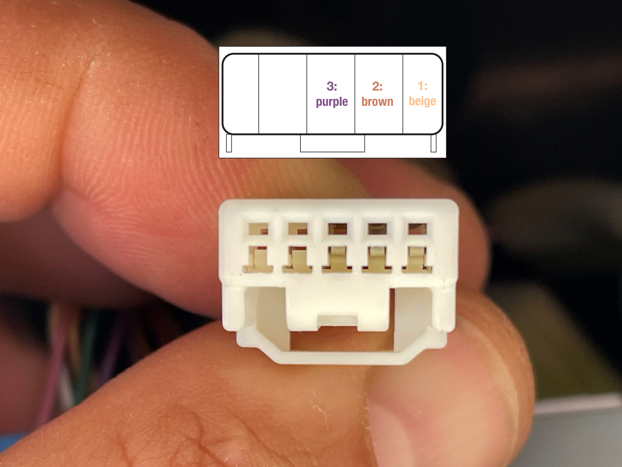
Hand brake connector
| Pin number | Wire colour | Description |
|---|---|---|
| 1 | Beige | Handbrake switch |
| 2 | Brown | Reverse signal (from junction box) |
| 3 | Purple | Vss from BCM |
| 4 | ||
| 5 |
April 2024: Looks like pin 3 (purple) is a Vss signal in some markets.
October 2024: A reader with a 2019 Swift Sport reports pin #2 (brown) is a reverse signal
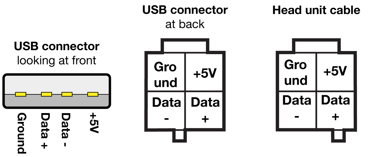
USB socket
Nothing too difficult here, though the wiring is not perfectly specified in the factory wiring diagrams. I’ve traced it through from the USB connector you plug a phone into all the way back to the head unit cable, but I would 100% verify this before making your own cables up.
Rear camera
Interestingly the car side wiring for this is not included in factory wiring diagrams, at least for Australian cars with the Bosch 7″ head unit. Note I’ll be doing any writeup from this based on the reverse camera fitted to those Australian cars: the reverse camera was only ever fitted once they arrived in Australia. This is also why the reverse cameras for Australia do not feature gridlines for parking assistance and cannot turn them on in the head unit; they are not a support function of the camera supplied.
It doesn’t help that the wires are mostly black, and noone seems to have properly documented this. I’ll keep digging and updating this as I go.
| Pin number | Wire colour | Description |
|---|---|---|
| 1 | Thin black | Video signal? |
| 2 | Unused – potentially camera video ground if using different camera? | |
| 3 | White | Video + |
| 4 | Thick black | Video – |
| 5 | Thin black | Ground? |
The commercially provided adapters are reported to not work correctly. Anecdotally, stereo installers have told me there’s a couple of pins to flip but I haven’t yet dug around to sort this out. The aerpro adapter they specify is APVSZ01, however, this is the one that I’ve not tested & may need a pin or two swapped to work correctly.
I have 4 main sources for trying to independent trace what the wiring does:
- Factory installation guide for the reverse camera to suit the 7″ Bosch units (part number 99195-78RA0-000)
- This thread on BigJimny discusses that the ‘red wire’ gets permanent power
- A Facebook comment from one of the Australian Jimny groups from the one person who showed what they did to make their factory reverse camera work with an aftermarket adapter
- Another FB comment about changes they did for compatibility with a Kenwood head unit (including steering wheel controls).
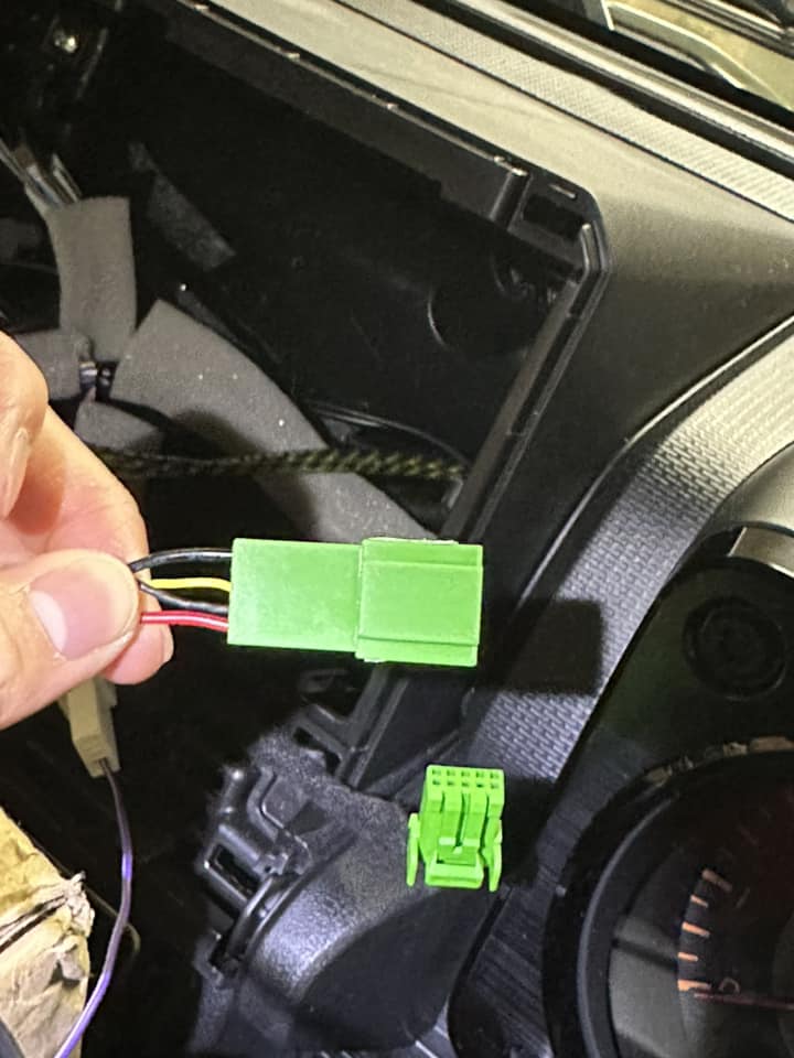
To ensure longevity in case of comment deletion, the following image is from the 3rd source, based on someone repinning the Aerpro connector and seemingly getting the factory Australian reverse camera to work:
The wiring shown on the installation notes for the factory reverse camera is as follows:
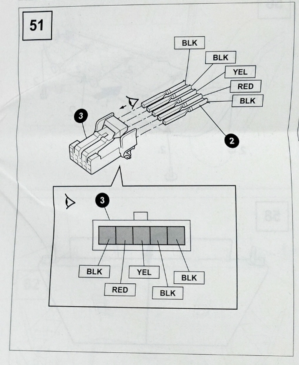
Clearly a bit more digging is needed to correctly sort out the wiring!
Microphone
9″ head units might have something different here, but I think the reason why people report poor audio quality on phone calls with the 9″ unit is because they probably have not correctly wired up the microphone preamp. The factory wiring accommodates this requirement, and it might be something you need to sort out with an aftermarket headunit, unless it comes with its own microphone.
Wiring is not properly described in any factory materials but I did find an Ignis discussion on wiring using the same pinout but different wiring colours.
The microphone connector might vary if an emergency call module is installed in Europe or other markets, without access to one of those cars I can’t verify.
| Pin number | Wire colour | Description |
|---|---|---|
| 1 | Light grey | Ground (shield) |
| 2 | Pink | Audio signal |
| 3 | Light grey | Ground |
| 4 | Light blue | Power (+5v?) |
Not much else to add to this one, I’ll pull the interior light down and inspect which wires go where at some point. Note that at the microphone only 3 wires are connected, the two grey wires join up to 1 somewhere along the harness. Phantom power can be a bit tricky; thus it is probably easiest to skip using the car’s microphone and instead just use whatever one comes with the stereo you’re installing.
Connector appears to be TE 1379658-2.
Removing the head unit
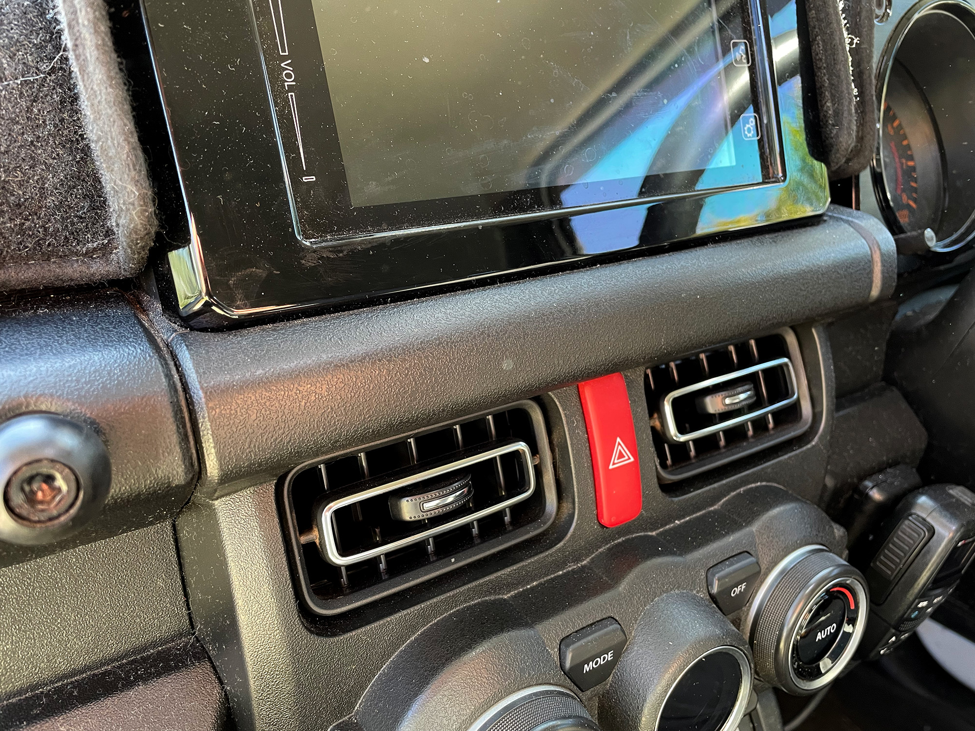
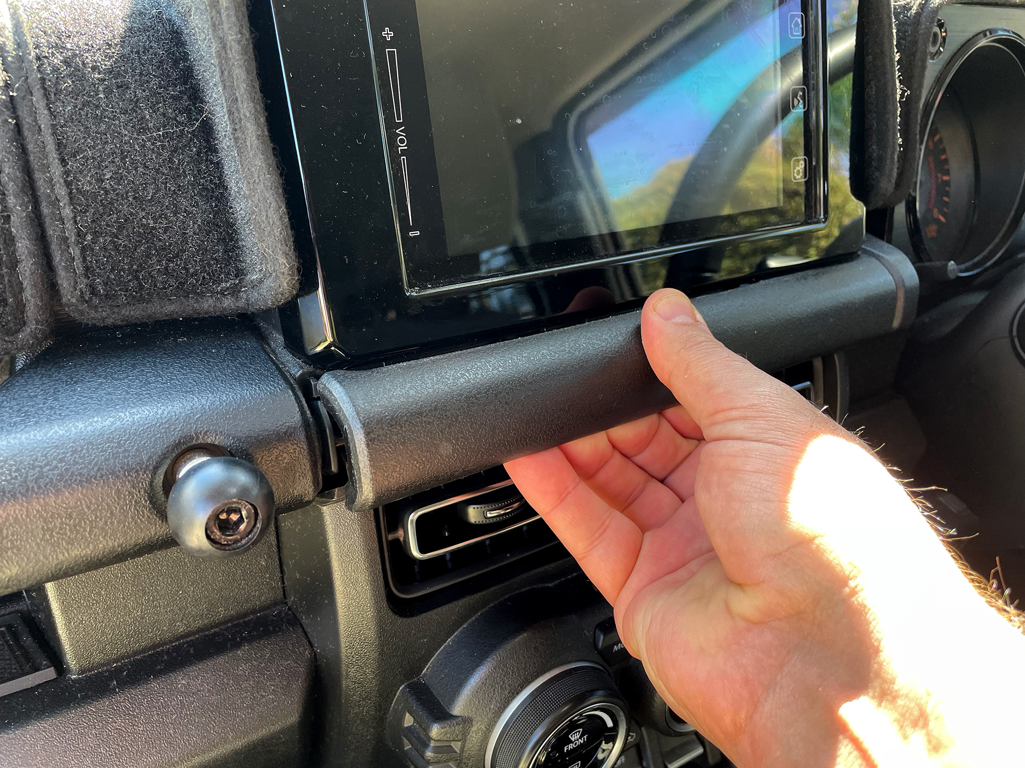
To start off with, you need to remove the lower cover just beneath the head unit itself.
The factory procedure just says to pull this out, but I found it easier to use a small trim removal tool to open up a gap from underneath on one side first.
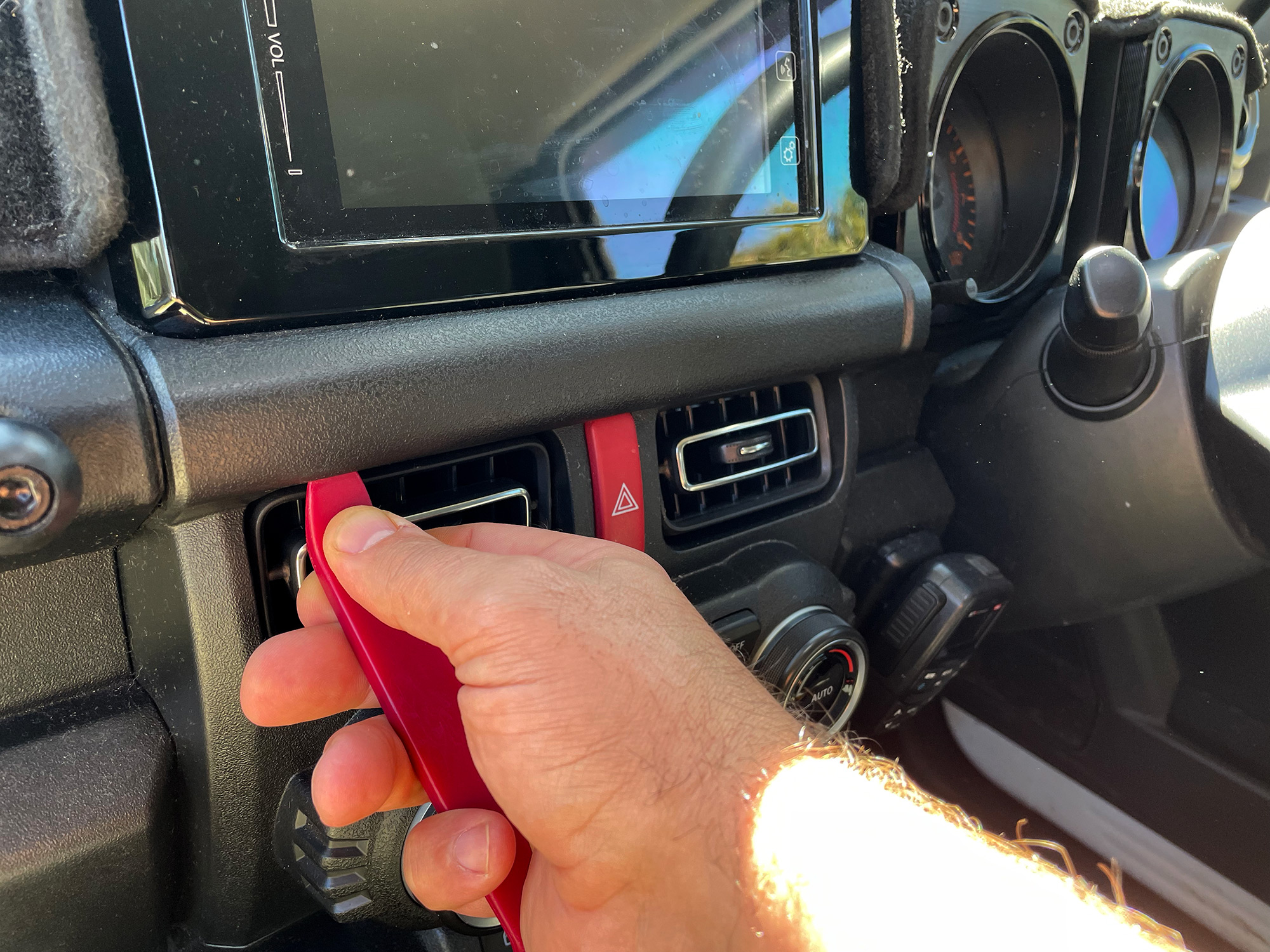
This panel then is pulled just straight out from the dashboard – not up, not down, just straight out.
There are 2 screws beneath the head unit you can now access.
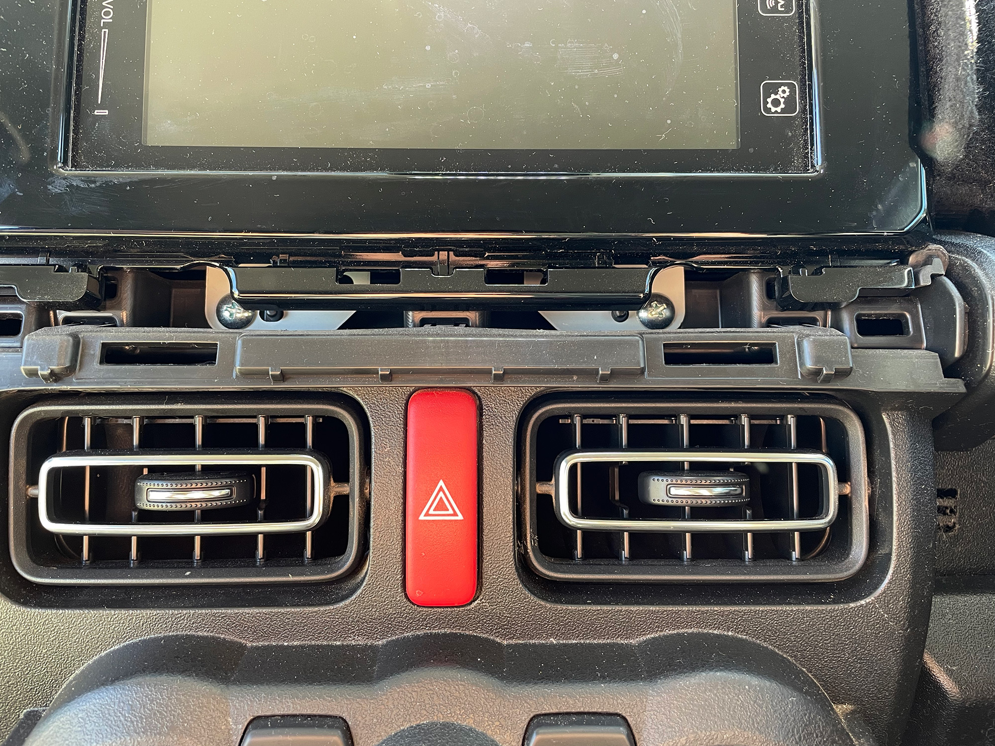
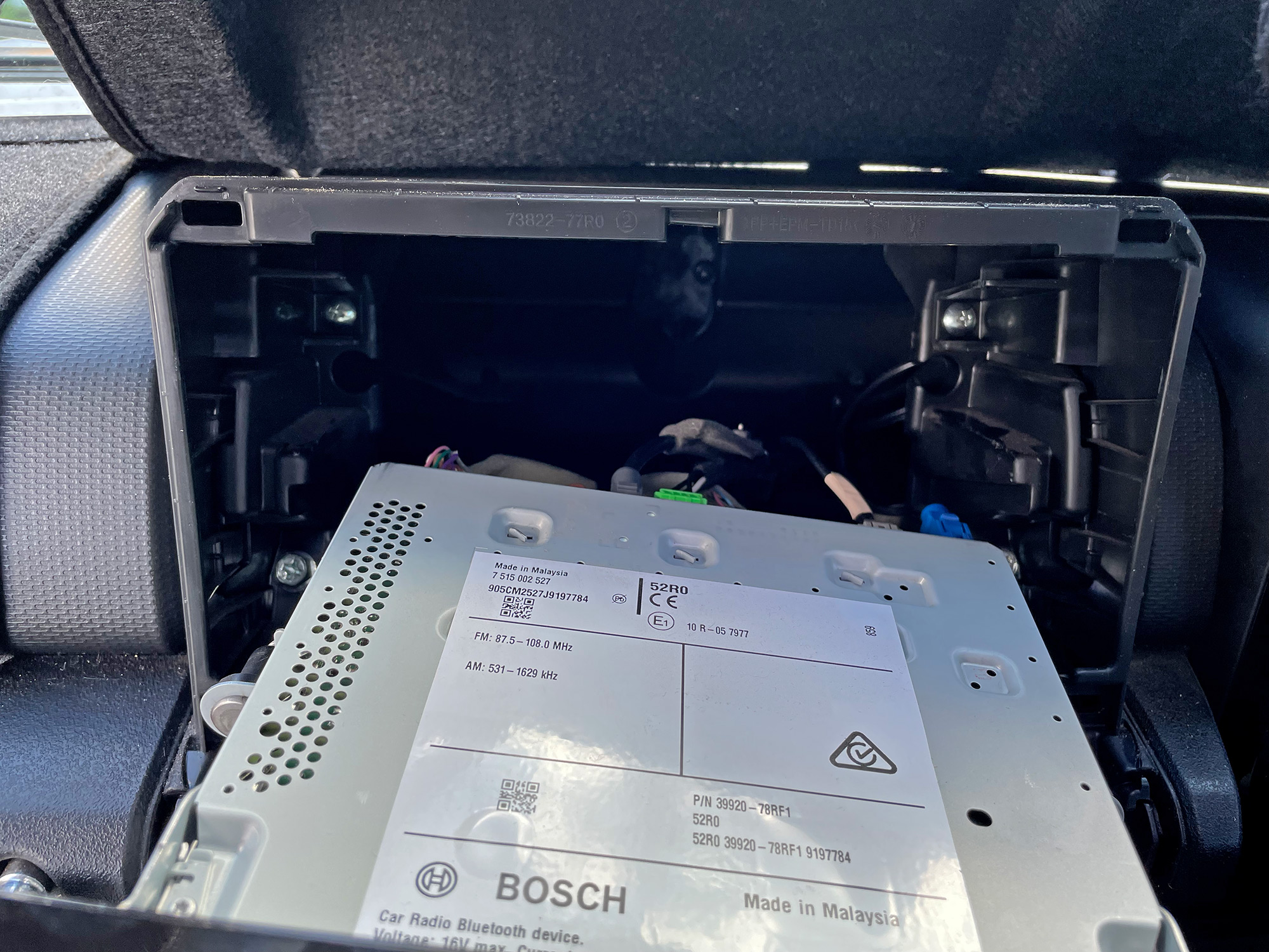
Unscrew these screws and remove them, and then the head unit just pulls out. Again, pull it straight from the dash. There are a couple of clips but it didn’t take me much force at all to get it out.
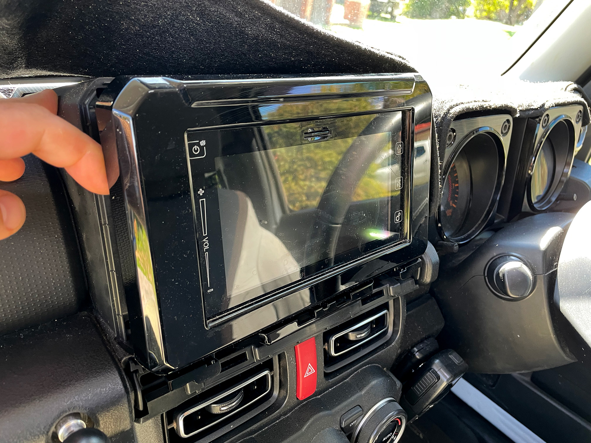
All very easy.
Note that the glossy black fascia comes out with the head unit; if you are fitting another head unit you need a fascia kit to provide you a nice looking fascia.
Aerpro do a fascia kit (which also comes with a bunch of the wiring you need): it is facia kit FP8496K
When putting the head unit back in, note that there are clips that you need to line up with holes at the top of the aperture to get the unit back in. It then just pushes back in, the screws go back in and the lower cover pressed back on.
Super easy infotainment system to deal with, really!
Speaker upgrades
Speaker terminals and wiring
This seems to be the main thing people have issue with, surprisingly enough. It’s actually relatively straightforwards to either make up your own harness to tap into the factory harness or even buy premade adapters.
The premade adapters required are Aerpro part number APS58. These provide you the appropriate connector to attach to the factory harness and then mate to your speaker. (Speaker terminals might be different to what is provided on these adapters, but that’s not hugely difficult to handle).
You can also buy a male and female connector set through Narva: part 56272BL is a 2 way connector set with terminals. You only need the female connector shell and the flat spade connectors; the male shell/ female spade connectors are what is already on the car’s wiring harness.
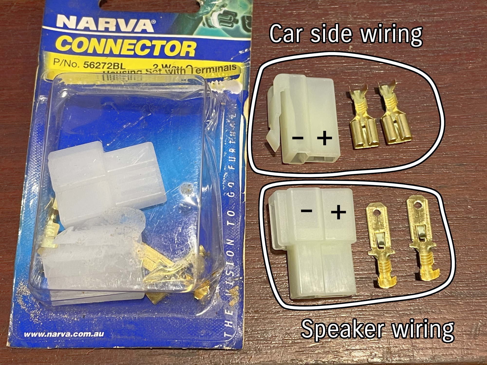
If you really want to go digging, the shell is a 2 way TE Connectivity unsealed 250 pin male connector shell and appropriate 250 pin spade connectors to latch into this housing. Eastern Beaver carry a compatible set as the Yazaki 250 unsealed connectors, 2 pin, just in a black plastic (Male 2P250-CNA is the part number to search for on that page). It is also available as Sumitomo LT series connectors are also available buit essentially discontinued (Male 2P250-LT).
Sourcing a set of genuine TE connectivity shells and terminals is a similar price as just buying the premade Aerpro speaker adapters so I recommend people go for the premade option unless you really want to make your own wiring harness.
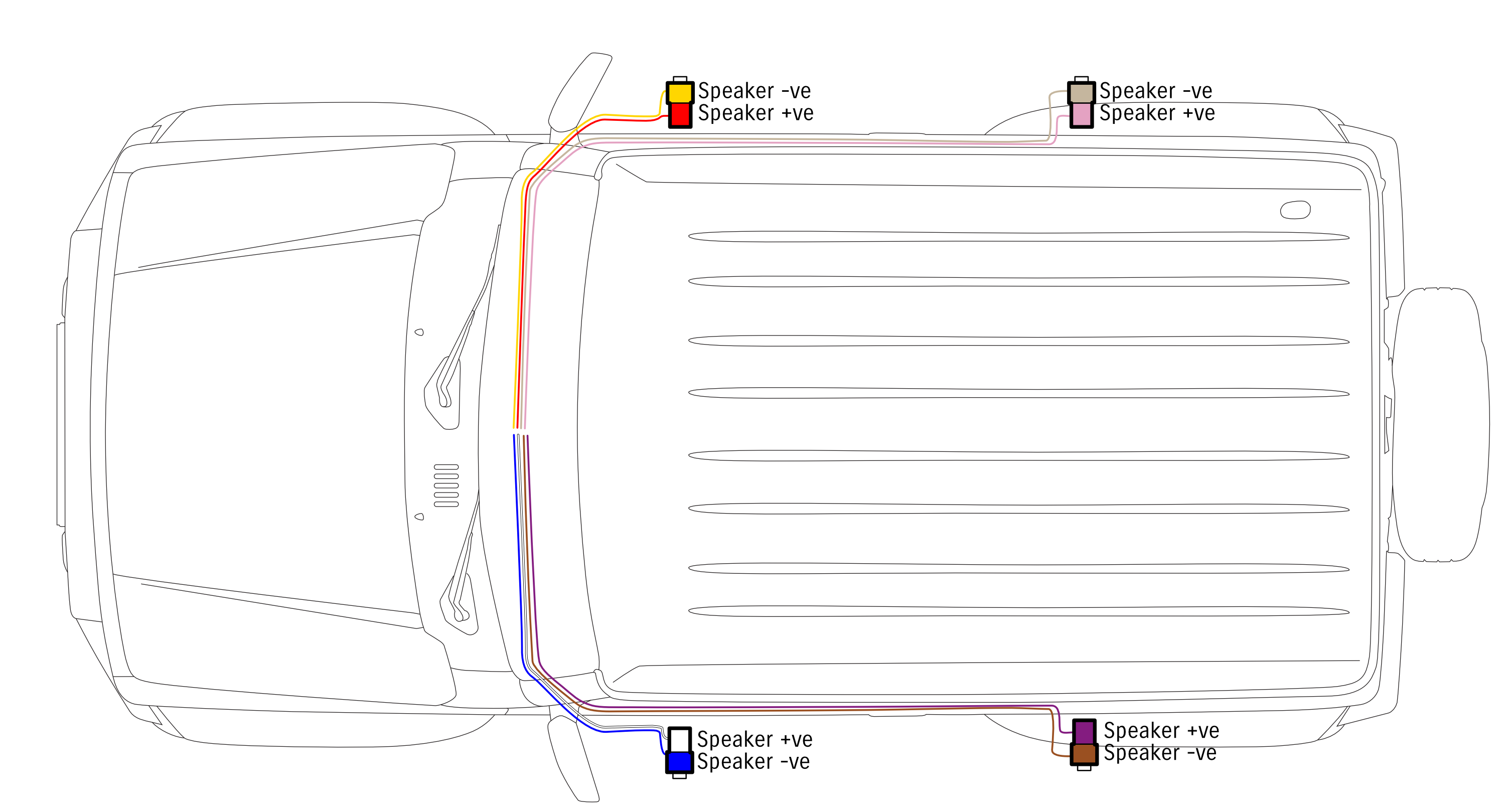
Speaker wiring, namely the phasing of the speakers, is the other thing a lot of people ask about. I’ve just isolated the speaker wiring here: note that 3 doors already have the rear speaker wiring run complete with factory T shaped connector on it, even the lites with the basic radio system.
Front speakers
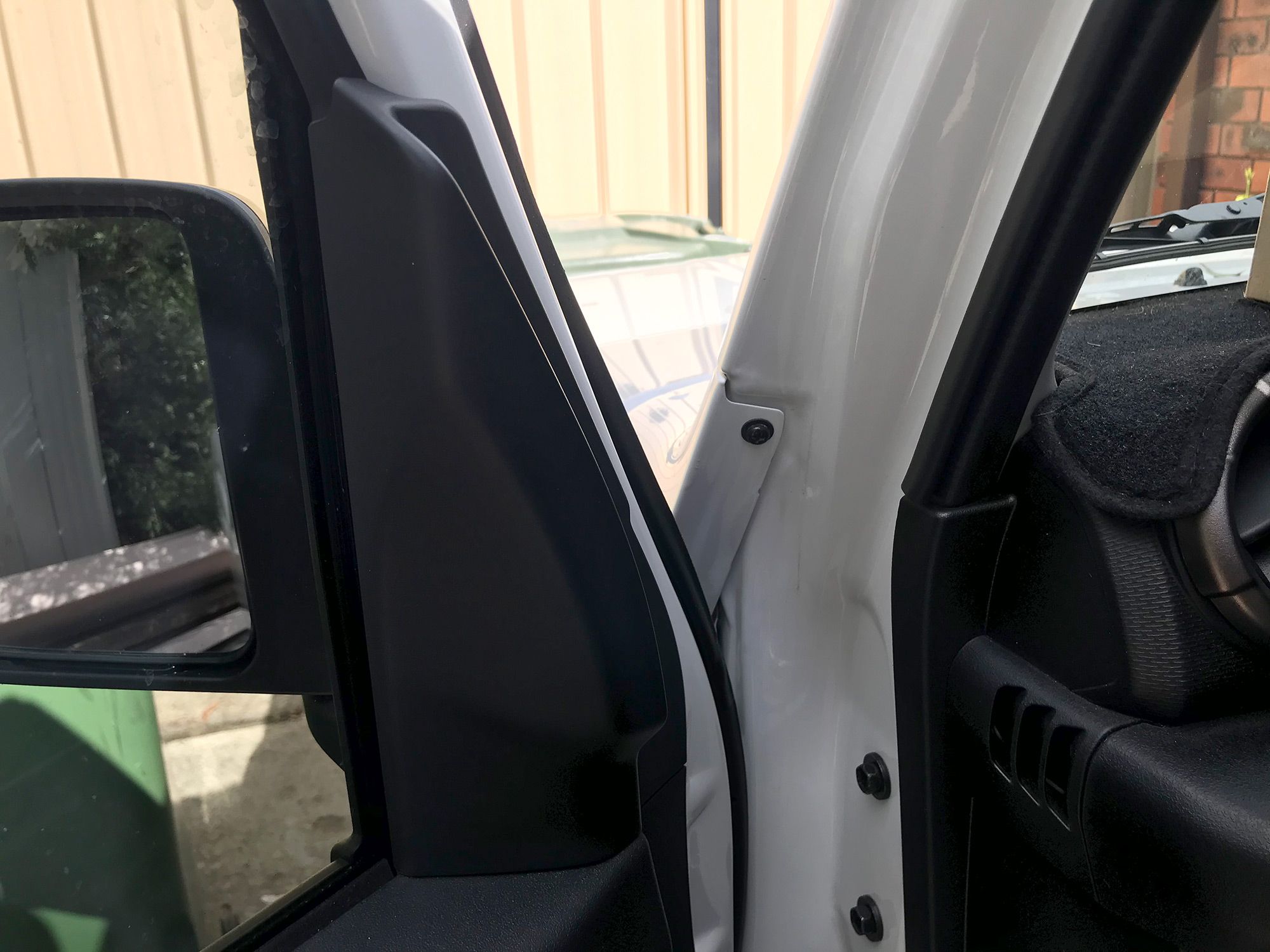
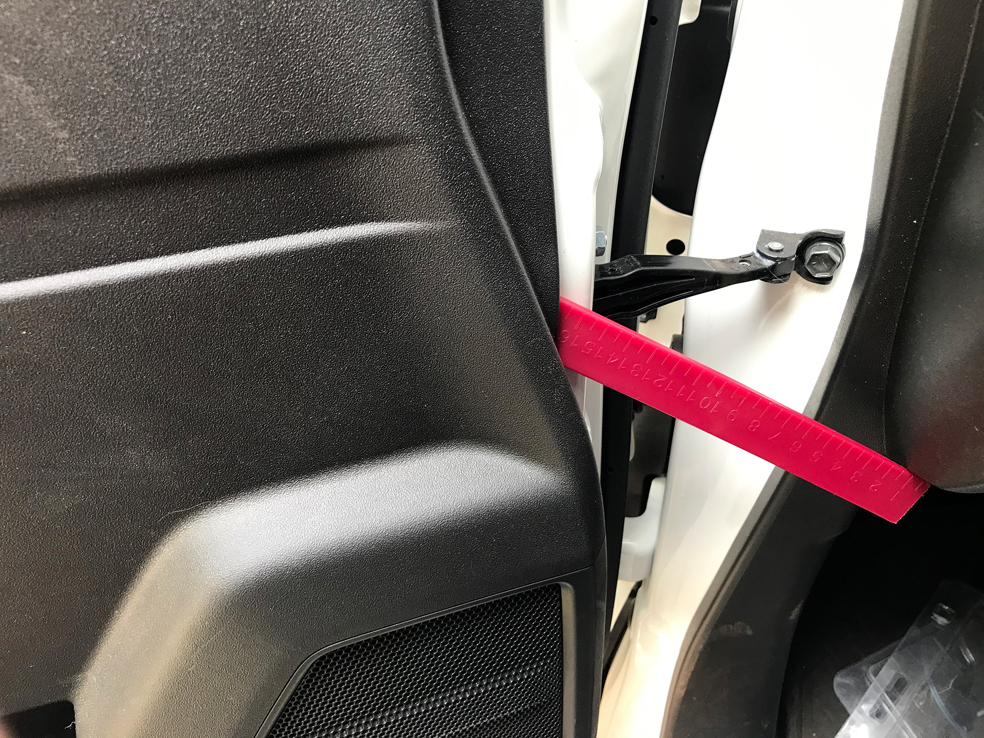
Door trim removal is where this starts. You first remove the bit of trim on the inside of the door at the top of the door trim. Just lever this away from the door with a trim removal tool, or if you have strong fingers you can just grab it and pull it straight out away from the door.

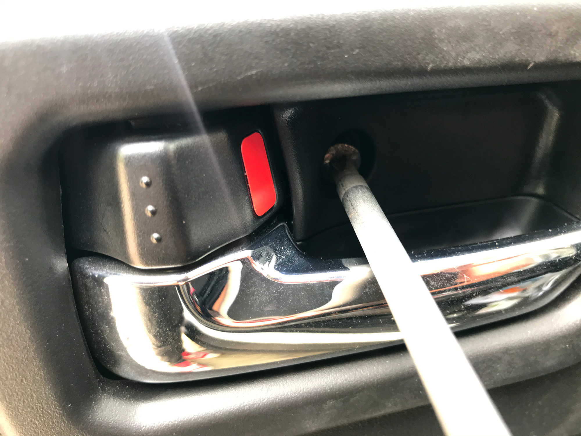
Next up there are 3 screws to remove. Two are just beneath the door pull handle, and 1 is by the door release. For some reason I didn’t take photos of the two beneath the door handle, but they are kind of obvious. The door release one is a bit sneakier for most people.
Again, just lever the trim straight away from the door using a trim removal tool.
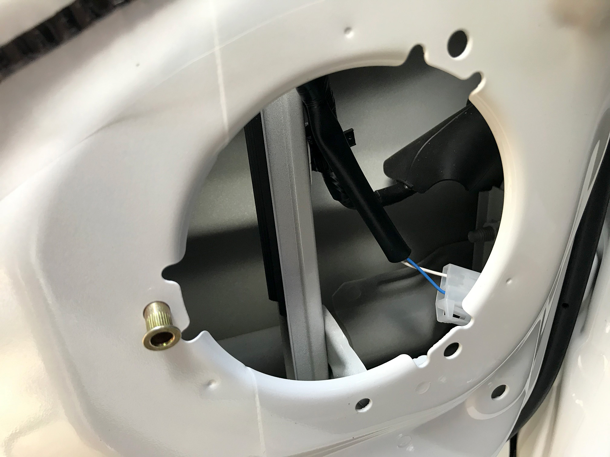
With the trim off, you will have your first look at the amazing 4″ speaker provided by the factory. If you’re very cheap and don’t care about destruction, you can actually punch the main part of the speaker out, remove it, and then you have an already installed adapter to the larger hole inside the door.
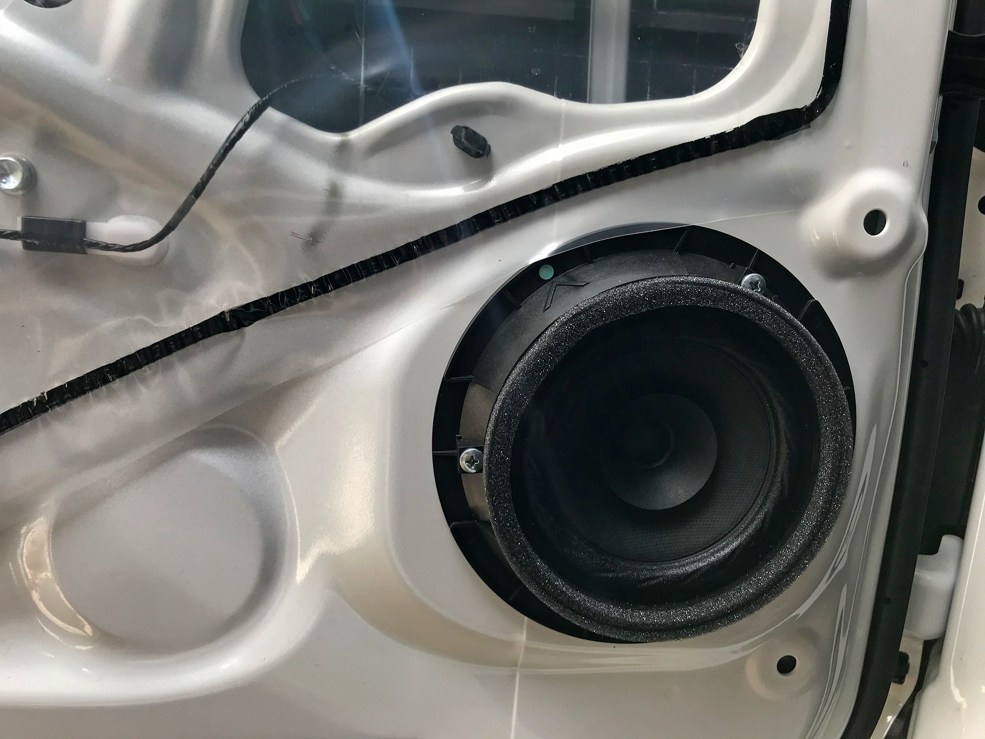
Unscrew the factory speaker with the 3 screws that you can now see, and this will reveal the wiring behind.
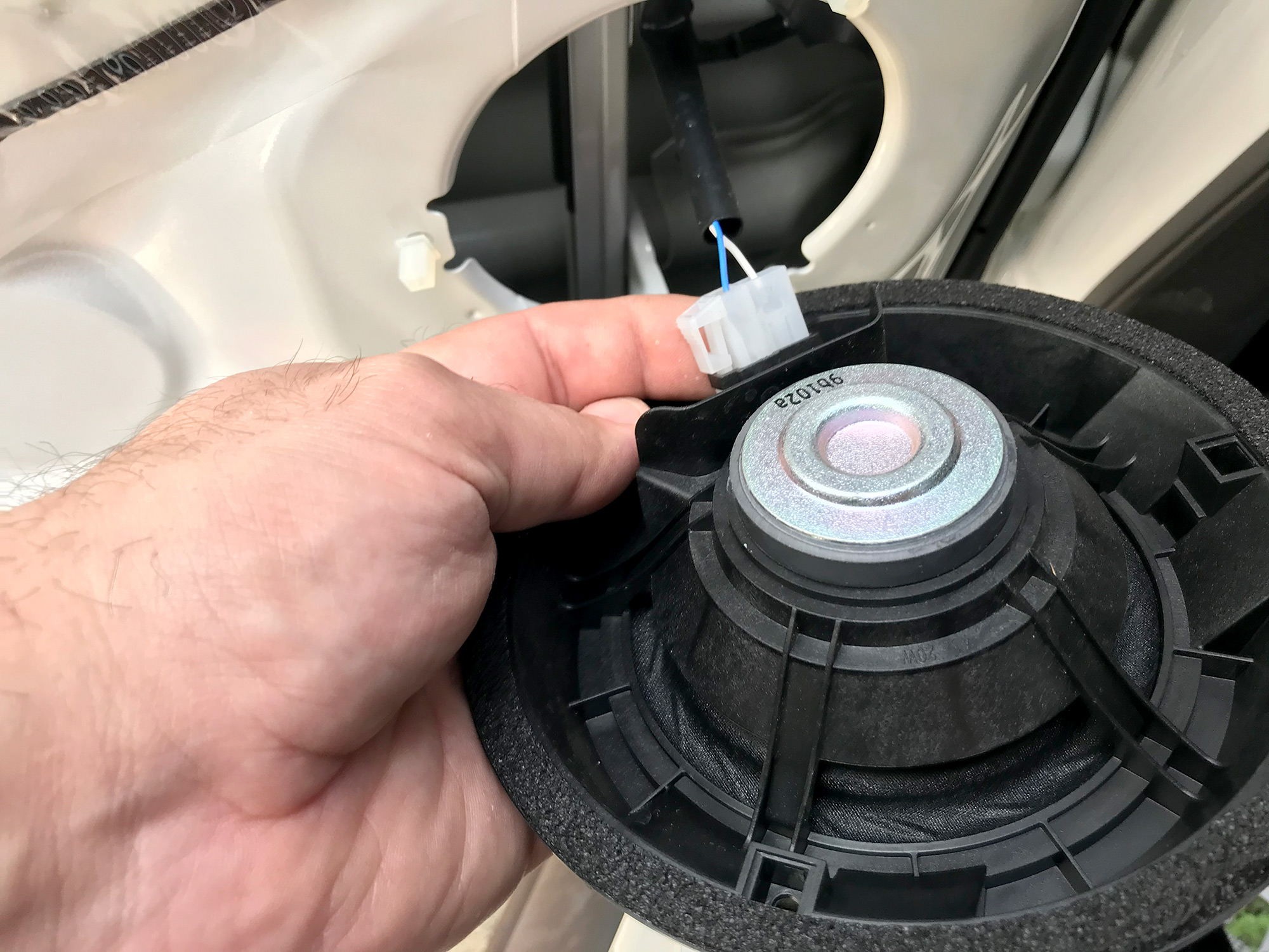
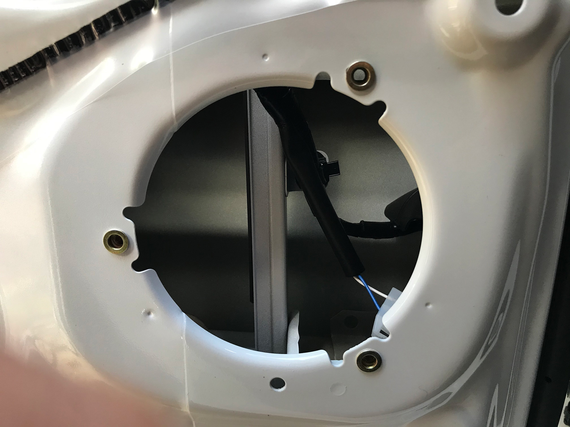
There are 3 plastic screw mounts into the panel. If you reach behind, you can squeeze their two tabs and remove them. The below picture shows you the two tabs per screw mount, if you squeeze these in then the plastic bit can be pushed out from the back revealing 3 holes in the door.
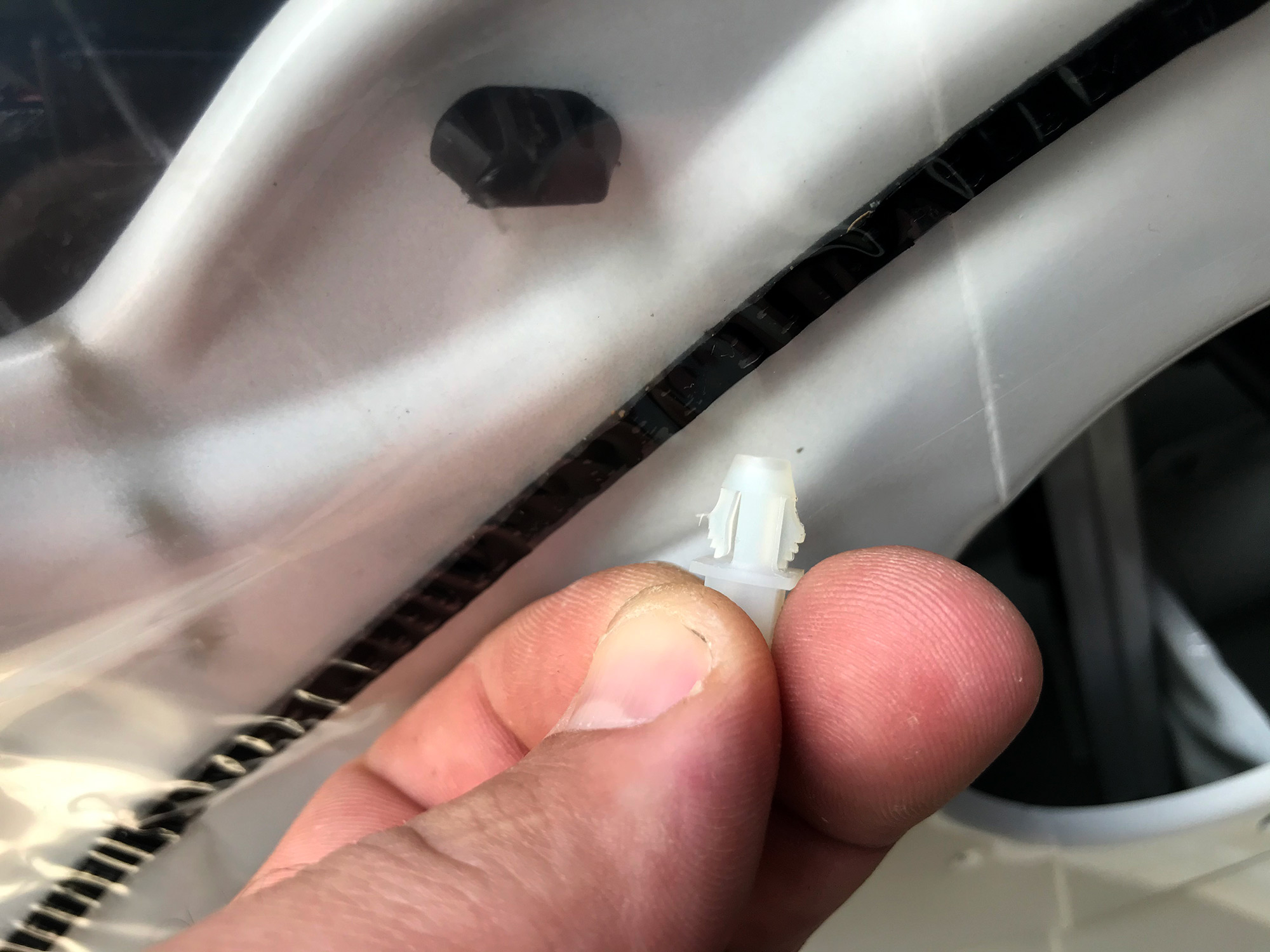
I believe the factory adapter rings came with their own speed nuts to allow screwing of the mounts to the doors using these now revealed holes; they were perfect for an M5 rivnut so I used them instead. I just like bolts in cars, I guess.
It’s just nicer having proper threads in there.
Quick note on wiring. Polarity on speakers sort of doesn’t matter, so long as all your speakers in your car work the same way. This means the speakers move the same way with a positive or a negative voltage applied to them; it sounds weird if they don’t!
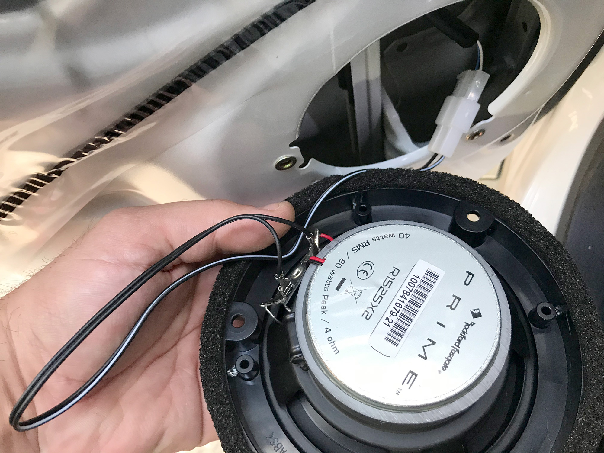
For the front left speaker: white is positive, blue is negative; for the front right speaker it is red for positive and yellow for negative.
As noted in the what you’ll need part, the factory brackets have holes drilled for the 13cm Pioneer speakers. A lot of 5.25″ speakers will have a slightly different mounting pattern; no biggie, just need a drill and you can sort this very easily. I used the speaker to ensure it was centred in the mount and just drilled 3 new holes slightly out from the originals.
At this point someone probably is going to ask for hole dimensions and stuff for the cutout in the door and the biggest speakers they can fit. The answer is… I don’t know. I suspect you could get shallow 6″ speakers in with appropriate adapter rings, but beyond that I can’t help much. 5.25″ definitely works though.
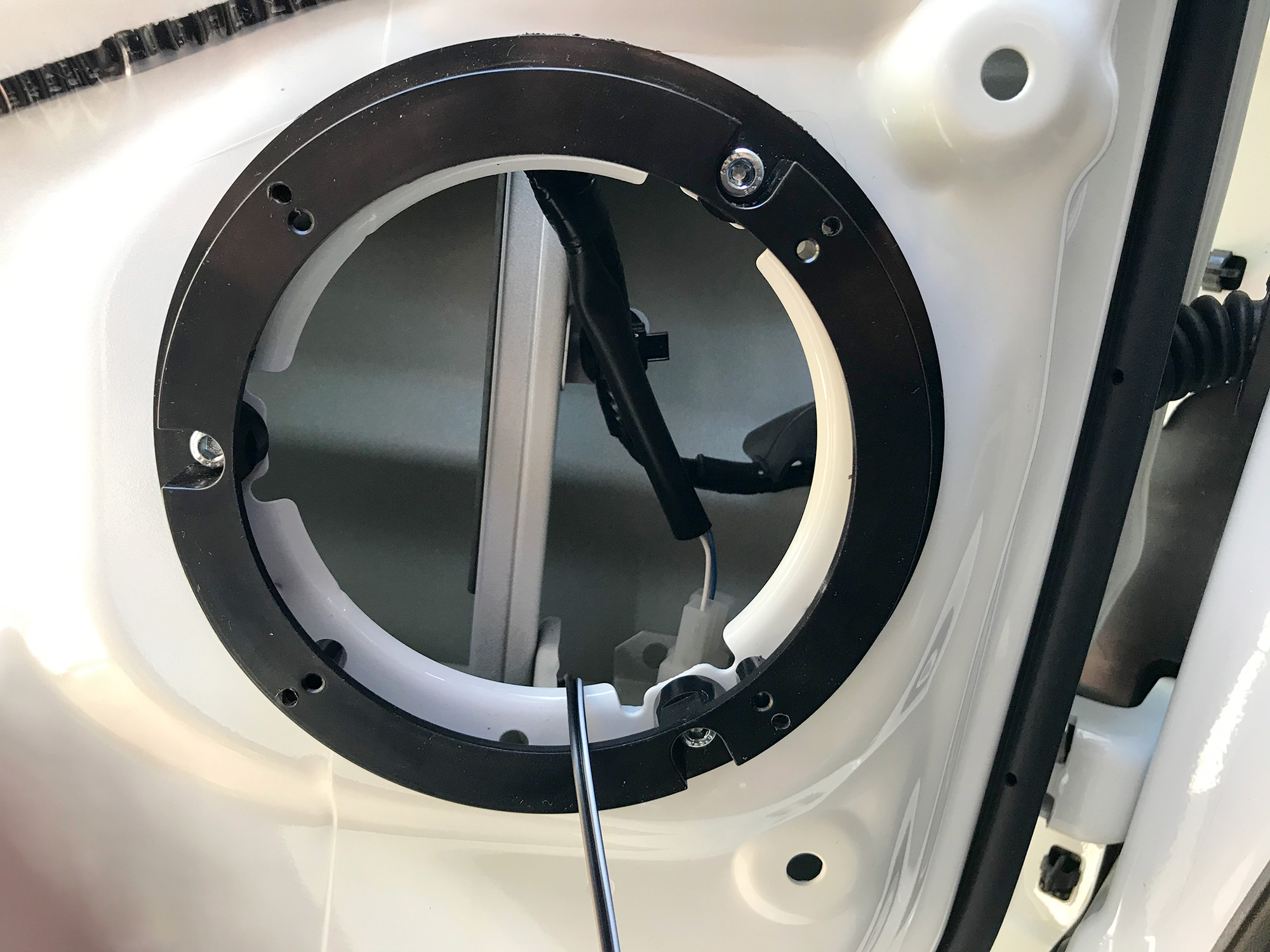
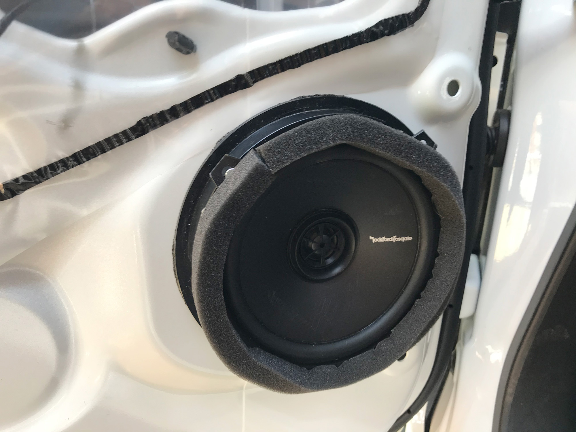
With the wiring sorted and the adapter ring in, just chuck the speaker in and screw it down.
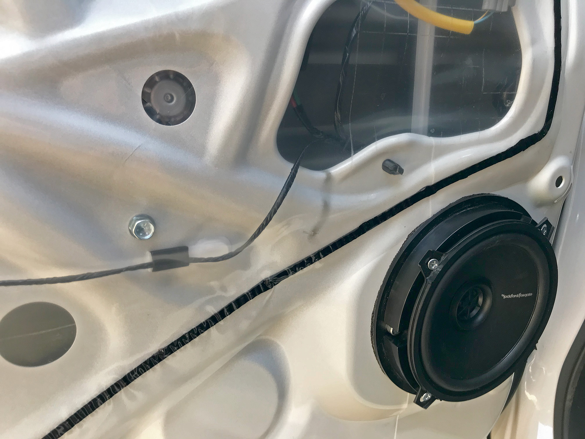
There is one final touch that is worth doing, and that’s using a little stick-on foam insulation to seal the speaker against the door trim. It’s a small thing but it will make a huge difference to audio quality.
Reinstall the door trim – remembering to put any of the plastic trim clips back into the door panel if they got left behind in the door itself – and then the upper trim and you’re sorted.
Rear speakers
I ran rear speakers for a few years, but after removing the rear seats I also decided to remove my rear speakers. They do fill out the sound a bit, but they don’t add much in terms of volume. If you’re on a budget, just spend up on better front speakers and sound deadening over putting in rear speakers, I think.
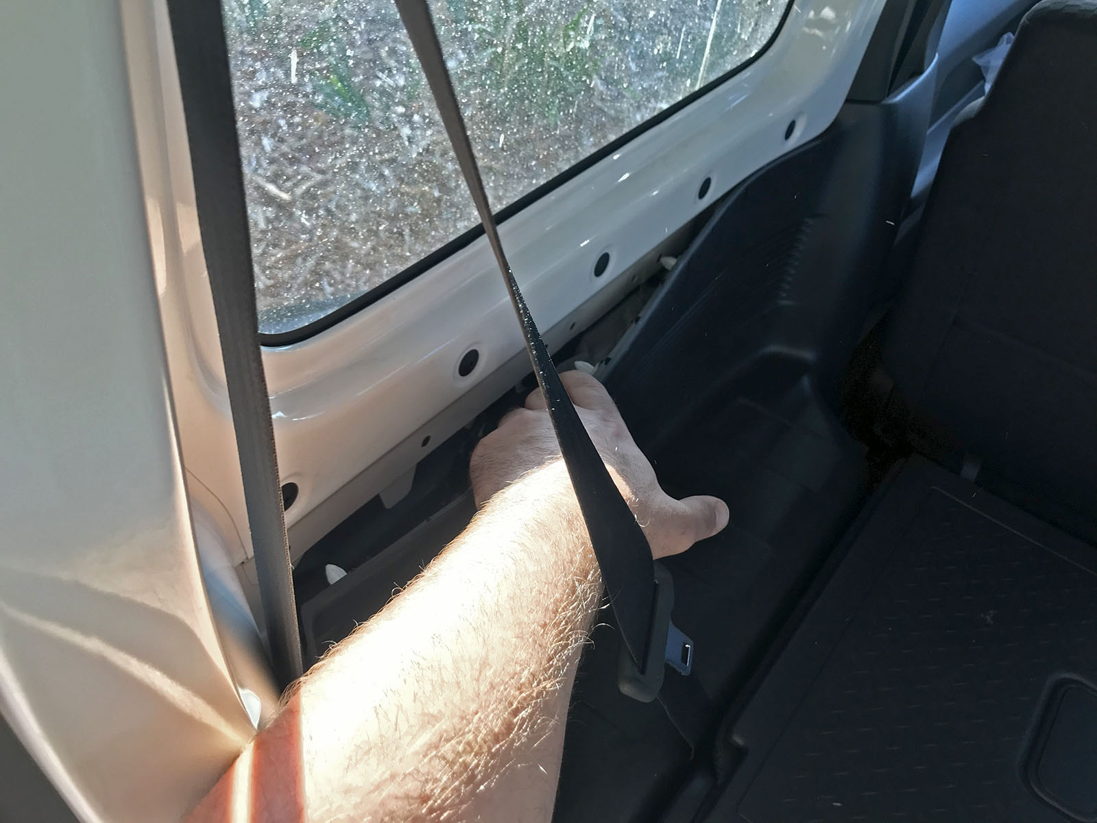
To access the area where the rear speakers are mounted, you can just remove the top part of the trim on each side of the car. Some people choose to remove the seats and then the entire trim panel, but I found it easier to just pop the top out.
Start by getting to the two trim rivets at the top of the trim where the seatbelt goes into the body of the car.
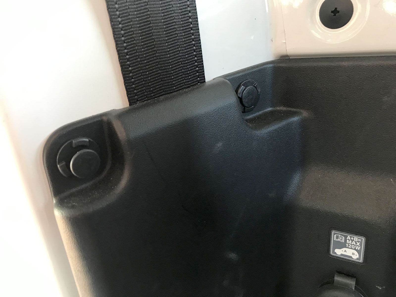
Then you can just pull the top of the trim away.
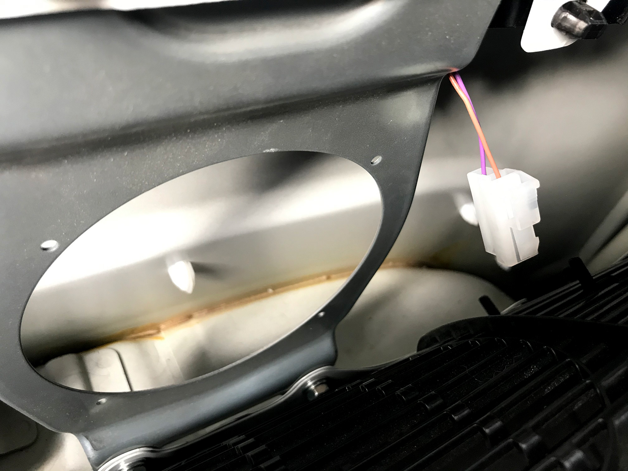
The wiring for rear speakers is already run for JB74s, it’s just taped up to the wiring loom where the speakers go on each side.
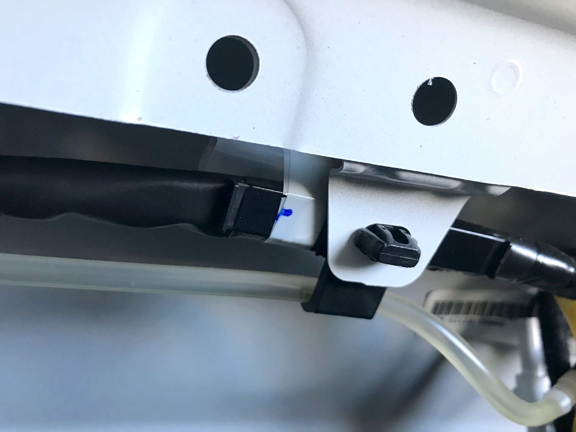
A note here on the wiring polarity: rear left is purple for positive and brown for negative; rear right has pink as positive and beige as negative.
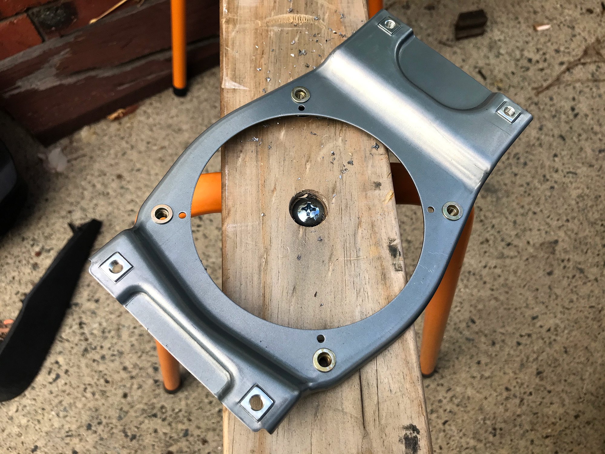
Time to offer up your chosen speaker up to the rear brackets.
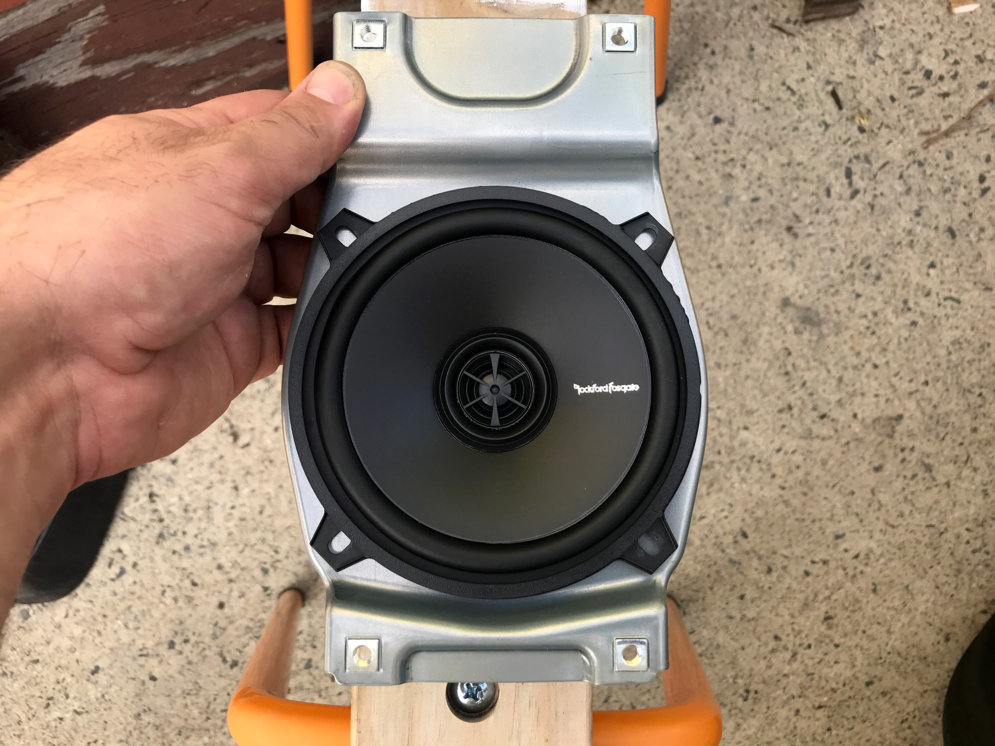
As noted, the speakers I have chosen don’t share a mounting bolt pattern with the Pioneers that Suzuki selected. That’s no biggie – there’s room for mounting holes further out on the brackets, at least for 5.25″ speakers.
You can do this as simply as drilling a small hole and using self tapping screws, but I decided to use M5 rivnuts to make it a bit fancier. To make this a bit nicer and consistent, use the speaker to mark out the first hole, and then drill & sort out mounting for this first hole alone; then mount the speaker fully using this, and then use the speaker to mark the other 3.
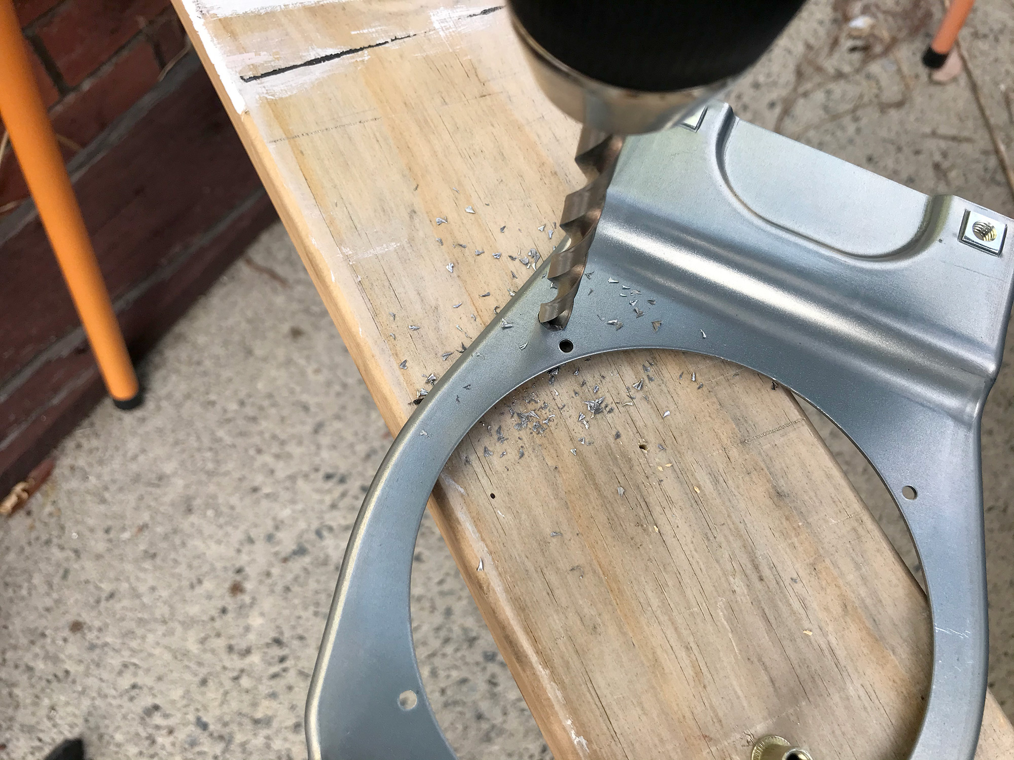
In my case, now the rivnut goes in for this first hole.
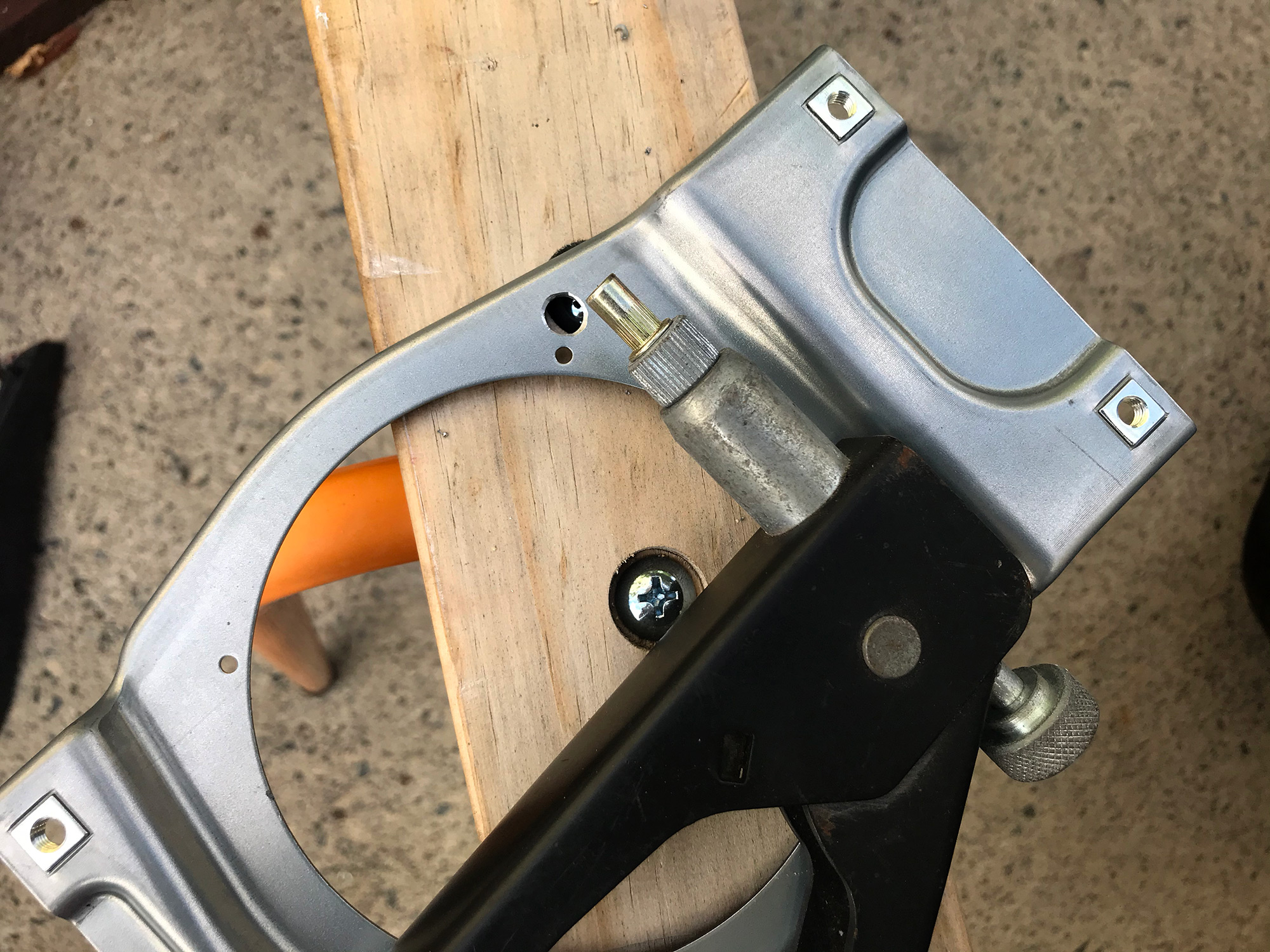
Then time to mark out the other holes and drill them and sort out mounting.
Speaker is then ready to be mounted up.
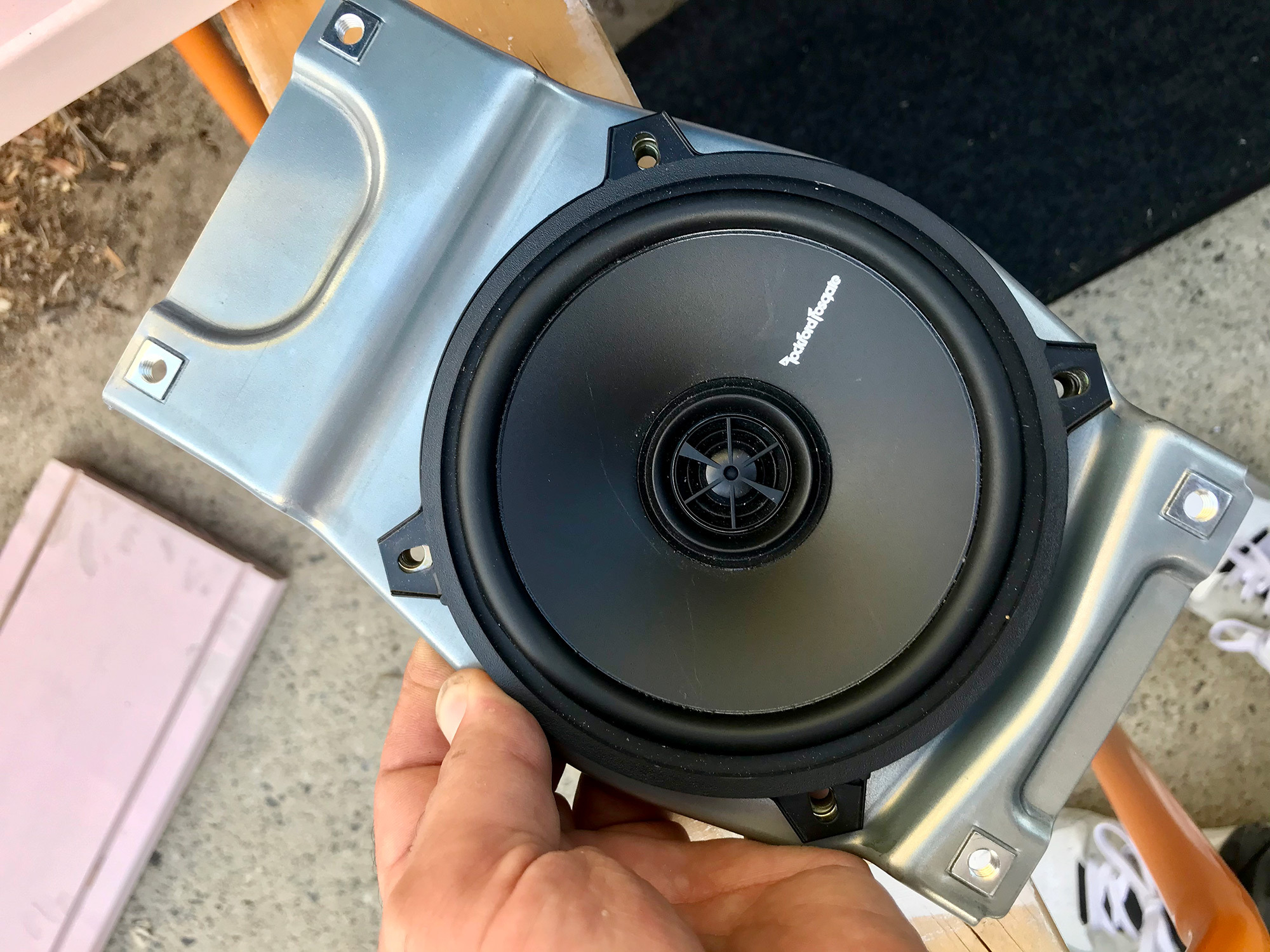
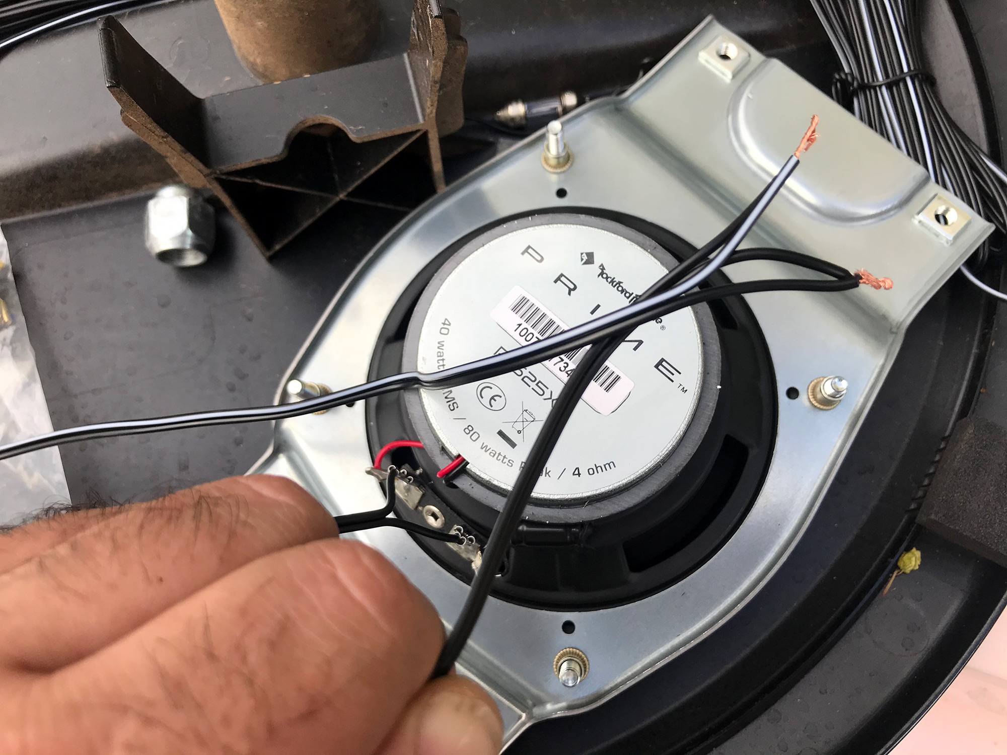
The final bit to sort here is the wiring. Here I’m doing some stuff to give me speaker outputs to the underseat subwoofer, just omit the 2nd set of wires if you are sorting it out.
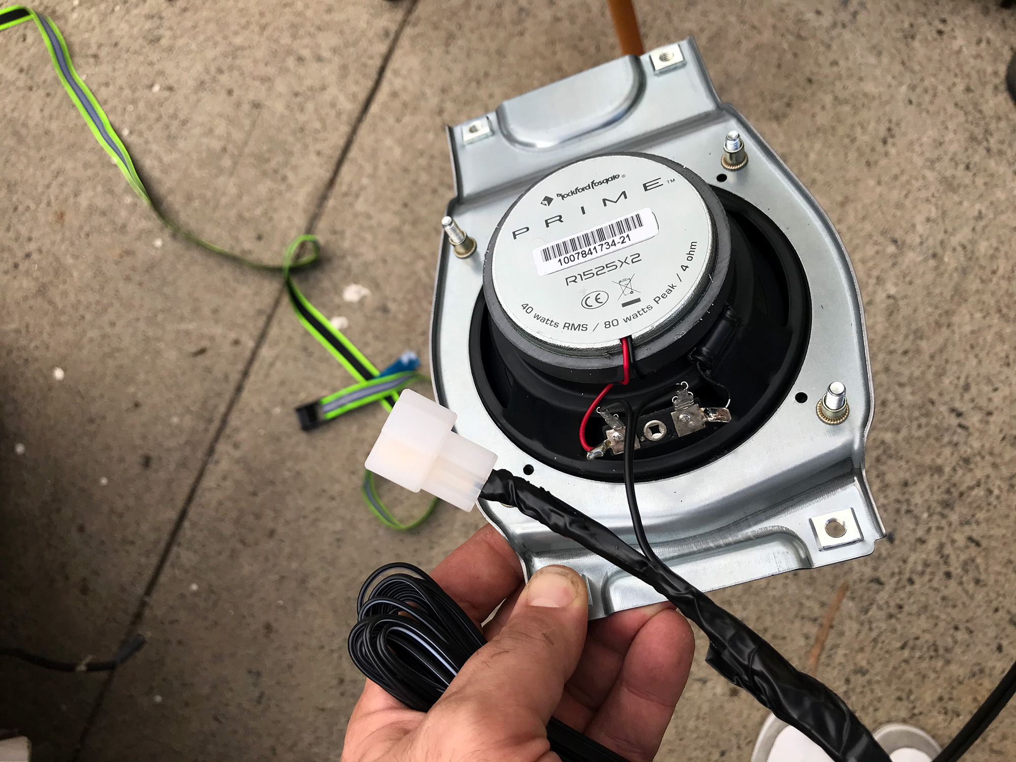
The rear speaker connectors in the car are T-shaped plugs; One option is these connectors and you can also use Narva 56272BL.
You only need the male side and if you want to make it easier, just wire it with male spade connectors and they’ll plug in.
As per the above, rear left is purple for positive and brown for negative; rear right has pink as positive and beige as negative. The other way to think of this is the top of the T of the connector is the negative terminal. So with this sorted, either get your spade connectors or the proper T connector sorted and wired up to your speakers.
Now you just put the bracket in and screw it into the car with the supplied screws. There’s an official torque spec for these bolts, hilariously: 5.5 Nm. I wouldn’t bother getting the torque wrench out for it.
Good idea to seal the speaker against the trim using some insulation, too, and there’s a little sound deadening over the holes for the speaker in the trim to remove, too. No pics of this apparently, it’s fairly obvious.
With everything sorted, trim goes back in and put in the plastic rivets by the seatbelt and you’re sorted!
Under-seat subwoofer
The factory 7″ head unit does not have line-level outputs; I believe the much maligned 9″ unit does. If you get an underseat subwoofer which accepts speaker level inputs then you’ll have an easier time. To get speaker wires down to it, I used the rear speakers & wired in output to the subwoofer at the same point as I connected rear speaker wiring up.
The factory route
There’s a couple of factory upgrades available.
- Ultimate package: 4 upgraded speakers and brackets plus the under-seat subwoofer. This is part number 990AA-01223-PK1.
- Upgraded speakers and their brackets together is 990AA-01223-PK2
- Underseat subwoofer 990AA-01223-PK3
- Upgraded speaker pair 99000-79BJ0-R00
- The factory speakers appear to be Pioneer TS-G1320F speakers.
There is also a semi-factory Japanese option using Pioneer 6.3″ speakers (though 4″ speakers are also compatible):
- UD-K124 speaker spacers for front speaker mounts
- UD-K301 tweeter mounts to replace interior upper door trim on A pillar side of doors
- UD-K124 rear speaker mounting brackets
- Appropriate Pioneer Carrozzeria speakers and tweeters:
- TS-C 1630 SII
- TS-F 1640 SII
- TS-C 1630 S
- TS-F 1640 S
- TS-F 1040 SII
- TS-F 1040 S
- Compatible tweeters alone:
- TS-T 730 II
- TS-T 440 II
- TS-T 730
- TS-T 440
5 door Jimny XL details
While I don’t have a 5 door Jimny, not am I likely to, this page does sometimes get referred to by owners with 5 door Jimnys.
The 5 doro Jimnys have some similarities and some differences; chiefly the head unit has some more functionality around stuff like fuel economy but also it has different wiring, using a 24 pin connector.
I believe the 5 door Jimny head unit is the Clarion sourced Smartplay Pro infotainment system. This owners manual is from an earlier model (a 2022 model head unit) but might be useful.
I don’t have ready access to 5 door wiring diagrams and there’s only so far I’m prepared to go rehosting other people’s content or things I can’t verify, however, this webpage looks like it could be a useful jumping off point for people with Jimny XLs looking for info on head unit wiring.