
Under bonnet compressor
One of the most fundamental things about 4wding is a need to change tyre pressures; drop them offroad, but then also put them back up once you hit the highway again. While you can carry portable compressors, permanently mounted ones on a vehicle are amazing to have at your disposal.
There are multiple options such as putting the compressor inside drawers in the back if you make a storage system, or even under the drivers or passenger’s seat. I quite like the idea of putting it under the bonnet, and ARB make a compressor designed for this. I do open the bonnet if I’ve done a lot of driving and want to use the compressor, though, mostly to release some of the underbonnet heat before inflating things.
Shopping list
- ARB compressor (CKMA12 is the right one – buy from your favourite reseller)
- ARB inflation kit: extension hose is ARB part number 171302, and then add whatever inflator you want e.g. digital inflator is part number ARB601
- TLR bracket (or, now what I run in Feb 2025 onwards: MOD underbonnet mount for Jimny 4).
- ARB Remote fitting kit (ARB part number 171314) + Kaon cap for air fitting (they have an aluminum option, too, for those who want fancy)
- 1.5m braided air hose, needs to be 1/4″ JIC fittings
- Switch, relay (at least 25A), fuse (also at least 25A: 40A recommended), other wiring stuff
Wiring stuff
This is often what people get stuck with. I wouldn’t bother with the ARB wiring kit, it’s pretty expensive and way more wire than you need for the Jimny.
The compressor suitable for this bracket draws 25A, so you will need a fuse and relay suitable at least for this. 40A is recommended based on the ARB wiring chart though.
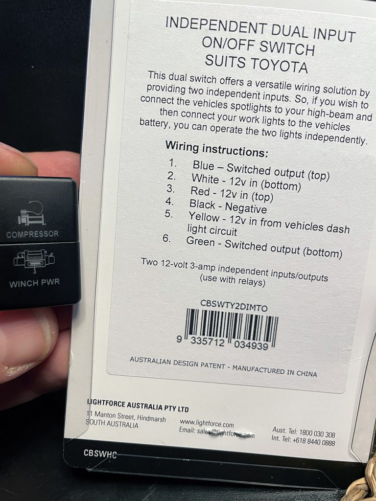
For the switch I actually use a Lightforce custom dual switch to suit ‘short height Toyotas’. One part of this switch powers the winch isolator solenoid and the other is for the compressor. Although I don’t plan on installing lockers, I did also get an ARB sized dual switch for the lockers just in case. If I fit them, this switch fits down in the centre console alongside the in-cab winch control switch. I just have all of the wiring done and tucked behind the centre console, with the potential to add it later. Details on switches and what fits where all here.
To make it easier I’ve included all of this wiring in case people do want to wire it up ready for lockers. You don’t need all of that side of things if you don’t plan on doing it, either. For simplicity in this wiring I also don’t include fuses or ground info, it’s taken as read you sort of understand how to wire up a relay.
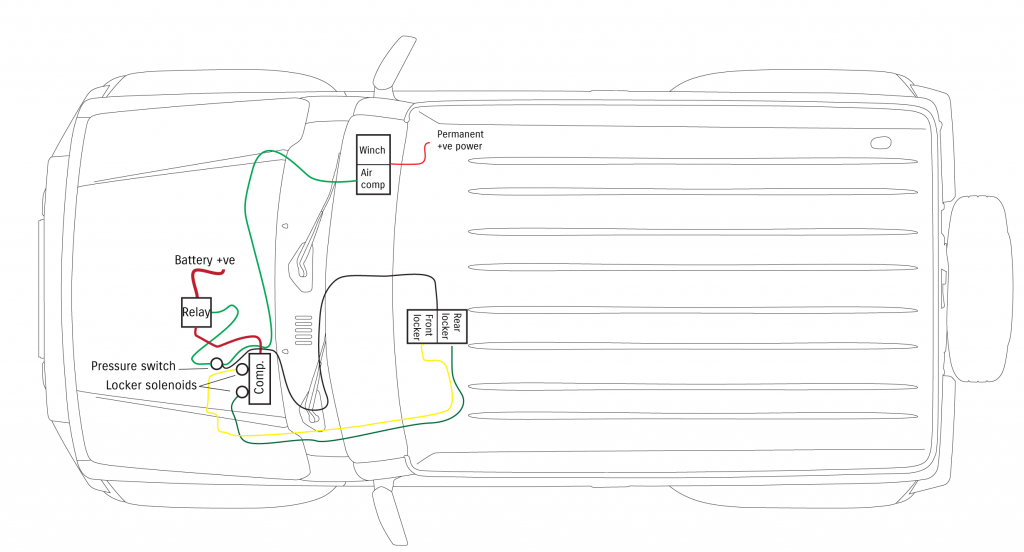
It’s a pretty simple wiring diagram, even if you incorporate the ability to switch air locker solenoids. Power into air locker switch comes from the relay switching line that also powers the compressor but has to be taken off before the pressure switch, not right at the relay. ARB usually wire these up so the front locker switch is powered by the rear, which would have the dark green rear locker cable going into the input of the front locker switch instead of how it is drawn here.
As before, note I did not draw fuses or grounds on here. Each of the other side of the locker solenoids needs grounding, the compressor itself needs a reliable ground, and the switching side of the compressor relay also needs to be hooked up to ground.
Fitting it into the car (TLR mont)
As per the shopping list, I power the compressor via a custom double switch in the ‘short Toyota’ size – this fits in the factory switch positions in the dashboard.
Installing the bracket is the main part of this whole DIY thing. The TLR instructions for the bracket are pretty comprehensive and I won’t repeat them here. I will add various notes to help make things easier.
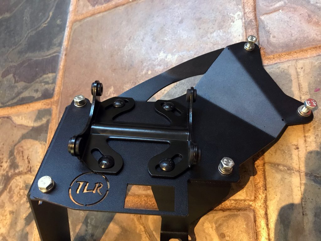
Start off by getting the bracket out and assembling the legs loosely inside the house to see how it all goes together.
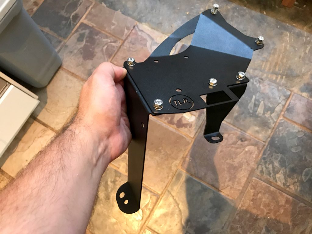
I also fitted the ARB compressor bracket on it at this stage too as that made life easier.
There are 4 round headed bolts that fit into the bracket to tighten it up with 10mm nuts underneath. Fit these and then you have a bracket ready for installation in the car.
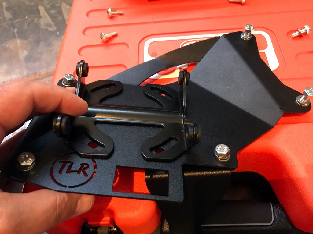
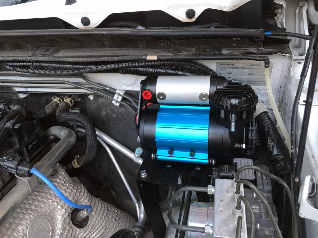
I also did a quick test fit to check the compressor onto the bracket here too. This is a good photo for me to explain the multiple ports on the compressor too. The red cap covers the port you fit a tee-piece into for the pressure solenoid and the other two ports are where you put in solenoids for controlling air lockers.
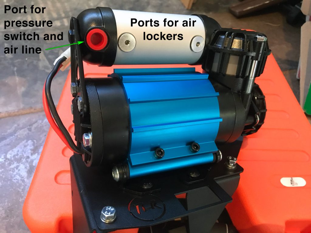
I’m not fitting air lockers but I actually did prepare wiring and stuff just in case I do in the future. This will save on some labour if I am getting them installed as I can have everything sorted out and working before they go in for the lockers.
At this point the bracket is ready to go into the car. To make it easier to position I didn’t have the compressor installed but it is doable to leave it installed.
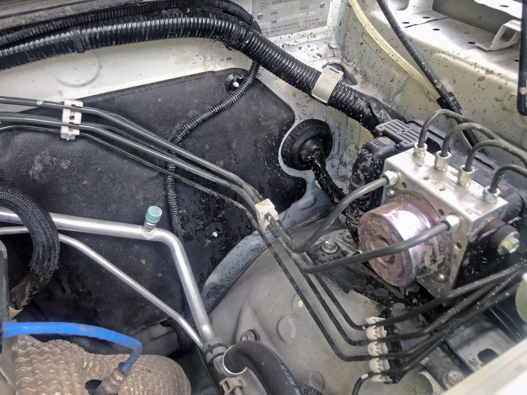
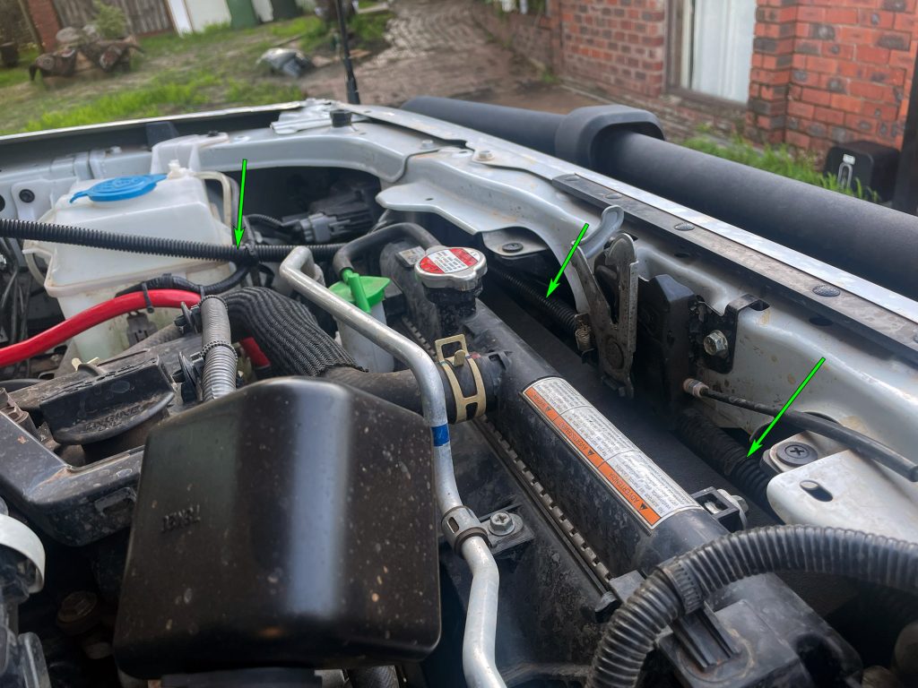
The compressor bracket fits on the passengers side of RHD cars. Because this makes it much harder to access the wiring loom grommet here, I would run any wiring you want through here before installing the compressor. For future proofing I ran a couple of runs of multi-core cable here along with the UHF antenna wiring.
Remember what I said about keeping the bolts loose on all the legs of the bracket and stuff? It helps to line everything up if you do this, rather than fighting the installation. At this point just follow the TLR instructions, and get everything bolted up and you’ll have a bracket all ready to go sitting there in the right spot.
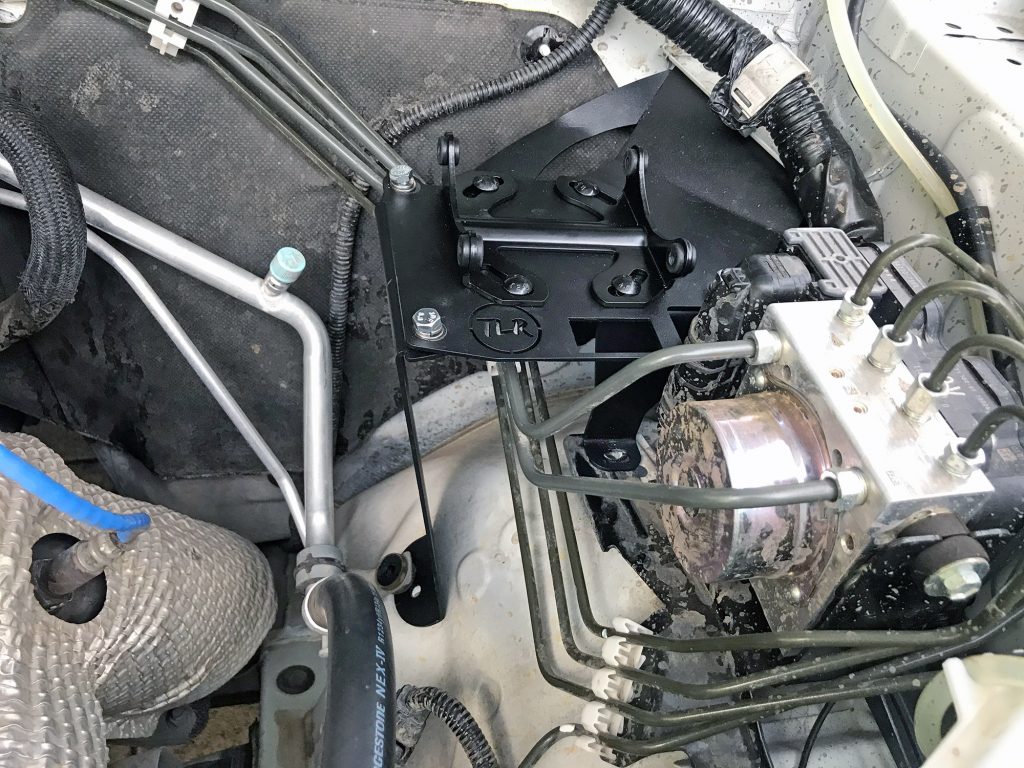
Compressor then just bolts onto the bracket, tighten everything up and you’re there for the main part of the physical installation
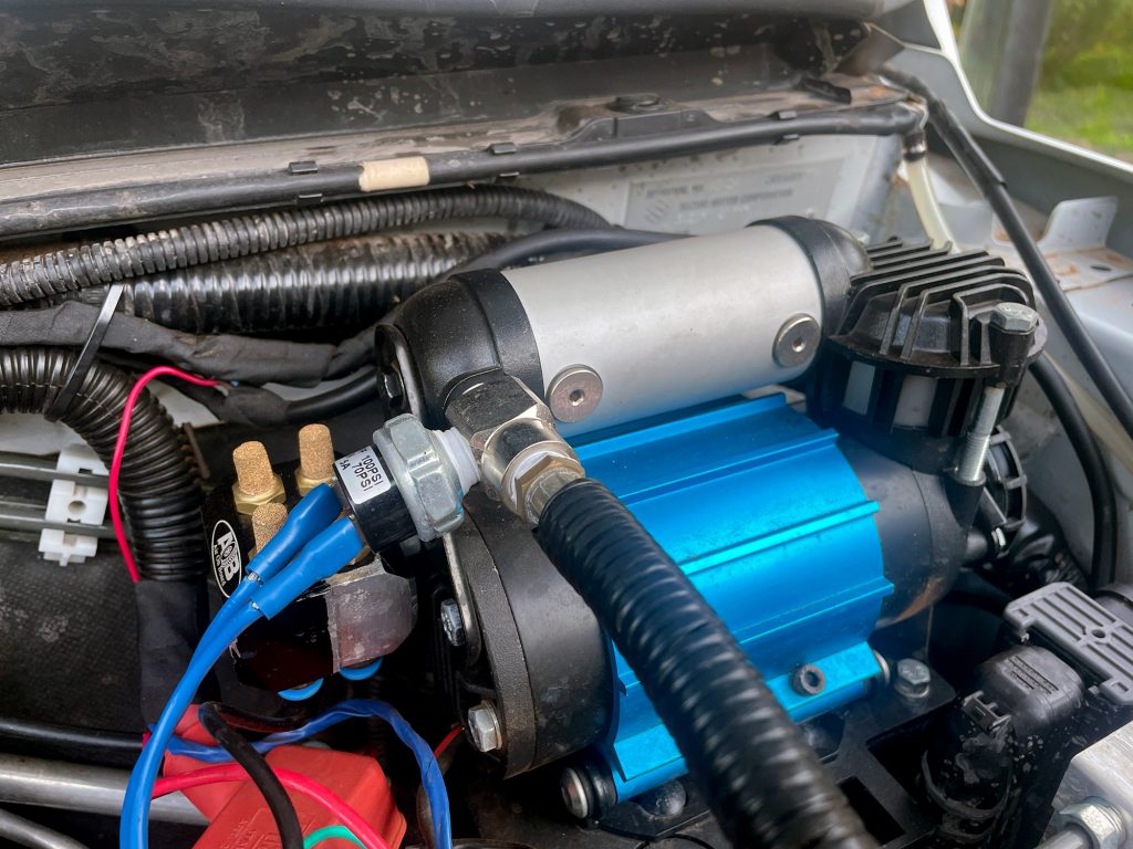
It’s important to put a pressure cutoff switch on the air fitting using the supplied T-piece. This controls power so that when the compressor is up to pressure it shuts off, and only runs once the pressure drops low enough to need it.
After installing the pressure sensor you can just install an air fitting under the bonnet and call it good. A lot of people do that and that’s fine – after all, you probably want the bonnet open for when the engine bay is hot to release some of the heat.
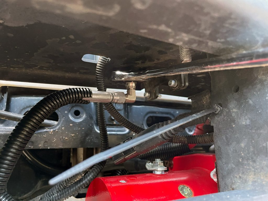
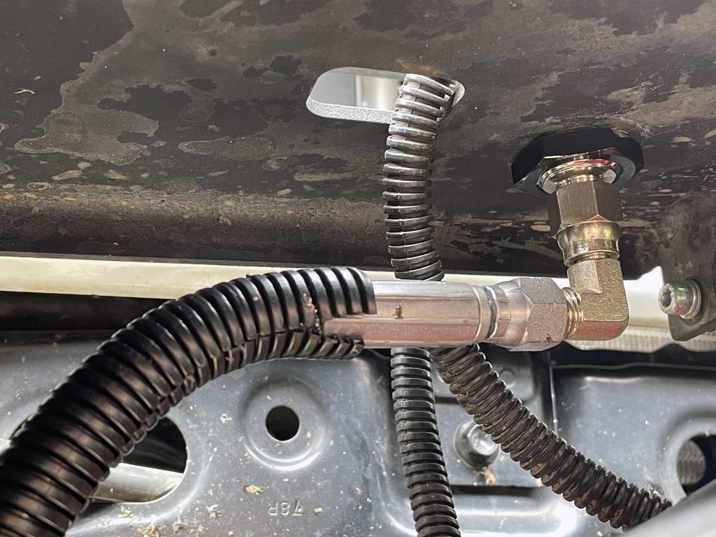
I went the extra mile and I used an extra braided air hose and the remote air fitting kit to install the air chuck down on the bullbar. I didn’t use the bracket supplied with the fitting kit, just drilled the appropriate sized hole in the bullbar behind one of the spot lights (20mm, I think?) and put the fitting in.
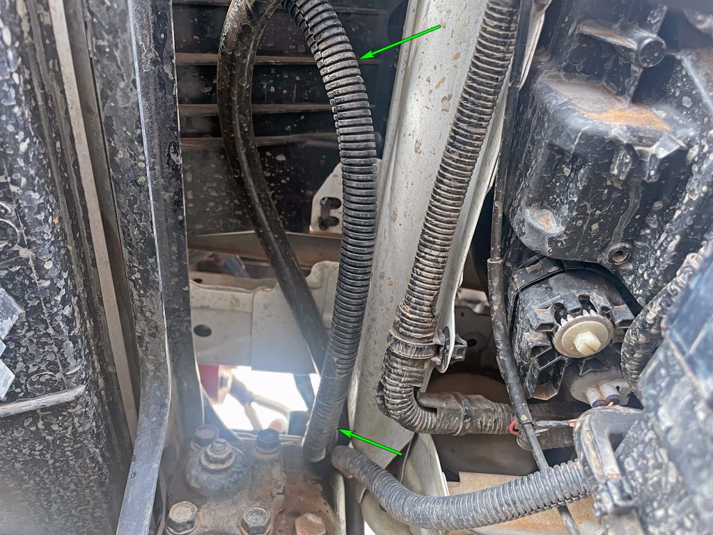
After running the hose down to it, a 25mm spanner is used to do up the fitting nice and securely.
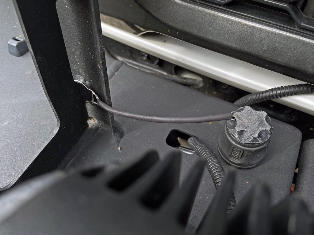
Kaon make a couple of caps that fit into the air fitting to keep dust/water/mud out of the fitting. I used a bit of lockwire to make up a nice little strap to hold the cap when it is removed from the air fitting so I don’t lose it on the side of a track somewhere.
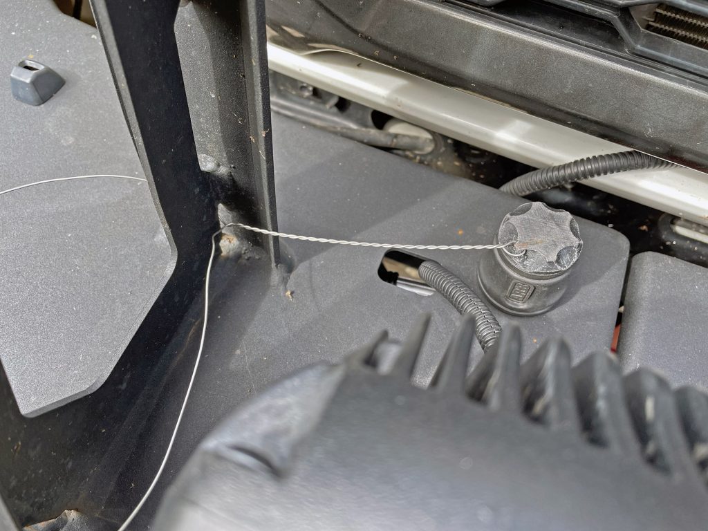
After twisting up the main run of lockwire, I put some heatshrink over it, twisted the other end around part of the bullbar upright and tucked the excess tail back into the lockwire so noone’s fingers will get stabbed by it. Easy peasy.
It’s a really good modification to the car to have air always with you, and saves on packing space. I quite like the idea of keeping the compressor in the cabin but I wanted to put other things under the seats so this is the best option for me.
MOD Jimny 4 under bonnet mount
In February 2025 I swapped from the TLR bracket to the MOD under bonnet bracket. This is actually an incredibly simple thing to install, definitely simpler than the TLR bracket, and has some pros and some cons.
Installation is best explained by their installation video
I did find, since I have aftermarket headers and maybe there’s some variance between South African and Australian ABS pipes, that the lower bolt was a bit of a tart to get installed – even more so than the video suggests. With factory headers there’d be a heap more room and would be a lot simpler. Straight 10mm ratchet spanner and a bit of patience helps here.
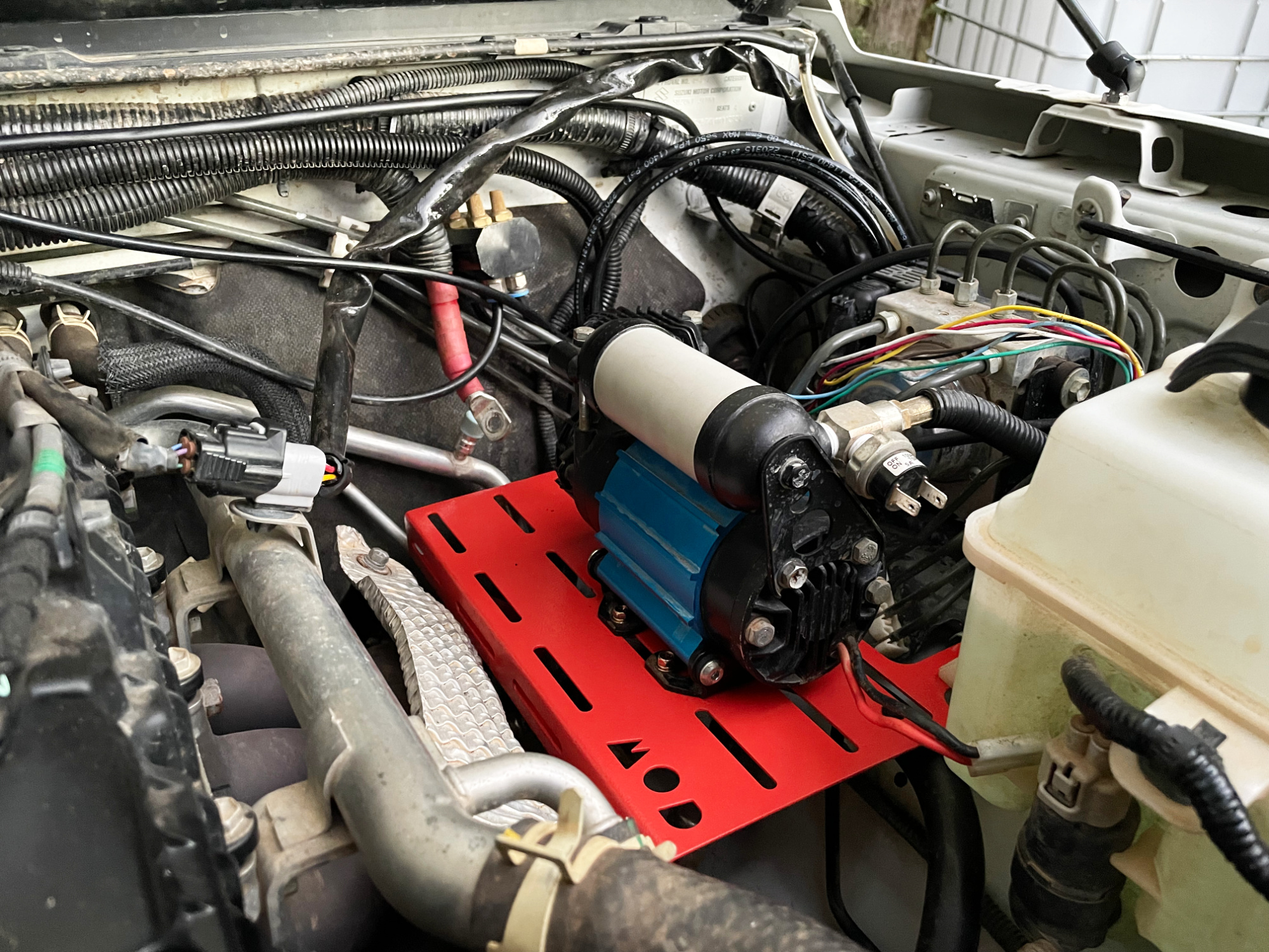
I used M5 bolts to mount the compressor to mine, and put the foot bracket on first and then mounted the compressor body to that. You can use the factory mounting bolts but I found they didn’t line up perfectly for a north-south installation (they would allow for an east-west orientation though!). I wanted to have my solenoids and pressure switch facing away from the heat of the exhaust (vs. they had to face towards the exhaust on the TLR bracket) and so it was important I could mount the compressor alongways in the engine bay.
Here’s a pic before I finished up the wiring; I installed this while I was doing an update to my onboard electrical stuff to make it a lot neater and tidier.
Upsides to the MOD mount
The compressor is lower; while not much that can be good for weight distribution; it’s also not so low that it’d be a problem with water.
It’s a little bit lighter, and cheaper, than the TLR bracket, and comes in some funky colours.
It will work with a range of compressors; you can adapt the TLR mount to take the TJM compressor, but it really is only designed around the ARB compressor. This MOD one can mount a bunch of compressors.
You have much easier access to the wiring on the passengers side: any time I wanted to route wiring to the passengers side I had to take out the compressor which was particularly annoying. This also makes troubleshooting easier.
Drawbacks to the MOD mount
The main drawback is it puts the compressor a bit closer to the exhaust; it would also probably rule out using it with a turbo conversion as there’s a lot less room near the headers. I’ll be making up a heat shield for mine that sits on the front row of mounting holes anyway, so this is not too bad.
The other drawback is you’d need to think about how you might mount different accessories to this bracket. I had my winch isolator solenoid mounted to the leg of my TLR mount & the breathers hung off the end of my compressor. I can’t do that as easily with this mount, so I just have to plan some things a bit differently. If I’d started from scratch with the MOD mount then probably I’d have already solved these though :D.